
 My Inquiry
 My Account


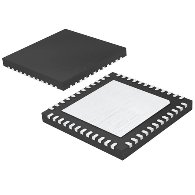
Analog Devices Inc. LTC3300HUK-2#PBF
- Part No.:
- LTC3300HUK-2#PBF
- Manufacturer:
- Analog Devices Inc.
- Category:
- Battery Management
- Package:
- 48-WFQFN Exposed Pad
- Datasheet:
-
 LTC3300HUK-2#PBF.pdf
- Description:
- IC BATT BALANCR MULT 1-12C 48QFN
- Quantity:
- Payment:

- Shipping:

Inventory:2,294
Please send an inquiry. Send us your inquiry, and we will respond immediately.
Product details
Overview
LTC3300HUK-2#PBF from Analog Devices is a fault-protected, high-efficiency bidirectional multicell battery balancer IC for transformer-based active balancing of up to 6 series-connected Li-ion or LiFePO4 cells with input common-mode voltage up to 36V, 92% charge transfer efficiency, 1MHz SPI interface with 4-bit CRC, and AEC-Q100 qualification for automotive battery systems.
For engineers reviewing the LTC3300HUK-2#PBF datasheet, LTC3300HUK-2#PBF pinout, LTC3300HUK-2#PBF application, or LTC3300HUK-2#PBF equivalent, key selection criteria include thermal rating (–40°C to 150°C), primary/secondary gate drive timing (tONP|MAX = 7.2 µs typ, tONS|MAX = 1.2 µs typ), precision current sensing (±1.7% VPEAK_P matching), fault protection (CRC, watchdog timer, overvoltage shutoff), and compatibility with LTC680x battery monitors.
Technical Context
The LTC3300HUK-2#PBF implements synchronous flyback topology using external NMOS switches on both primary (cell-side) and secondary (stack-side) windings, with independent RTONP/RTONS resistor-programmable maximum on-times (7.2 µs and 1.2 µs typical) and matched ±1.7% peak current sense thresholds across all six channels. It supports both single-transformer (CTRL = VREG) and multi-transformer (CTRL = V–) configurations.
Its robust serial interface features 5-bit addressability, 1MHz clock rate, CSBI/SCKI/SDI/SDO signaling with built-in watchdog timer (1.5s timeout), cyclic redundancy check (CRC), and readback capability. Fault detection includes cell overvoltage (5.0V max), undervoltage (1.8V min), thermal shutdown (155°C), and broken-connection protection during charge/discharge cycles.
Key Specifications
| Parameter | Value and Actual Design Meaning |
|---|---|
| Cell count | Balances up to 6 series-connected cells per device; stackable to >800V systems via daisy-chained devices. |
| Operating temp | –40°C to +150°C junction temperature - qualified for automotive under AEC-Q100, enabling under-hood BMS deployment. |
| Charge efficiency | Up to 92% transfer efficiency at 3.6V/cell - minimizes heat generation and extends balancing time per cycle. |
| Current sensing | VPEAK_P = 50 mV ±1.7% matching - ensures balanced current distribution across all 6 primary channels. |
| Serial interface | 1MHz SPI with 4-bit CRC and 5-bit address - supports up to 32 devices on one bus with error-detecting packet integrity. |
| Max on-time control | tONP|MAX = 7.2 µs (primary), tONS|MAX = 1.2 µs (secondary) - programmable via external resistors to prevent MOSFET shoot-through and current-sense resistor failure. |
| Supply regulation | VREG = 4.8V ±0.4V @ 0–40mA - powers internal circuitry and external logic; POR at 4.0V ensures reliable startup. |
Pinout & Package
48-lead (7mm × 7mm) plastic QFN package with exposed pad (Pin 49) tied to V–; requires soldering exposed pad to PCB ground plane for thermal and electrical integrity. θJA = 34°C/W, θJC = 3°C/W.
| Pin/Terminal | Circuit Role | Design Meaning |
|---|---|---|
| G1P–G6P (Pins 23,26,29,32,35,38) | Primary-side NMOS gate drivers | Drive external FETs connected in series with transformer primaries paralleling individual cells - enables bidirectional energy transfer per cell. |
| I1P–I6P (Pins 22,25,28,31,34,37) | Primary winding current sense inputs | Measure cell-side current with 50mV threshold and ±1.7% matching - critical for accurate per-cell charge/discharge control. |
| G1S–G6S (Pins 1,3,5,7,9,11) | Secondary-side NMOS gate drivers | In single-transformer mode (CTRL = VREG), only G1S is active; others are NC - reduces component count in minimal-BOM designs. |
| I1S–I6S (Pins 2,4,6,8,10,12) | Secondary winding current sense inputs | Monitor stack-side current with 50mV threshold and ±0.5% matching - ensures precise total energy transfer into/out of adjacent cells. |
| RTONP / RTONS (Pins 14 / 13) | Max on-time servo reference inputs | Resistor-to-V– sets tONP|MAX/tONS|MAX; clamps volt-second product to prevent core saturation and FET damage. |
| WDT (Pin 20) | Watchdog timer output | Precision current source pulls low during valid communication/balancing; goes high after 1.5s timeout - forces all balancers off on fault or host stall. |
| A0–A4 (Pins 43–47) | 5-bit device address inputs | Set unique SPI address (0–31) by tying to VREG (1) or V– (0); enables daisy-chained control of up to 32 devices on one bus. |
Key Features
| Feature | Design Value |
|---|---|
| Bidirectional synchronous flyback architecture | Enables charge transfer both from cell to stack (discharge balancing) and stack to cell (charge balancing), minimizing total balancing time and power loss. |
| Fault-protected serial interface | Includes CRC packet checking, watchdog timer, readback verification, and automatic shut-off on voltage/thermal faults - eliminates silent failures in safety-critical BMS. |
| Programmable max on-time clamps | RTONP/RTONS resistors set precise tON limits per winding side, preventing magnetic core saturation and MOSFET destruction during current-sense resistor failure. |
| AEC-Q100 qualified operation | Rated for –40°C to +150°C junction temperature with full parameter guarantees - meets automotive reliability requirements without derating. |
| Seamless LTC680x integration | Dedicated signal compatibility and timing alignment with LTC6802/LTC6803/LTC6804/LTC6811 family - simplifies system-level BMS design and firmware reuse. |
Applications
| Electric Vehicle Battery Packs | Grid-Scale Energy Storage Systems |
|---|---|
Use Scenario: Balancing 12–24S Li-ion modules in traction battery packs where cell mismatch causes capacity degradation and thermal runaway risk. IC Role / Device Role / Timing Role: LTC3300HUK-2#PBF acts as the active balancing controller, synchronizing with LTC6811 monitor to execute per-cell charge redistribution every 10–60 seconds. Use Value: Achieves <10mV cell-to-cell voltage spread after 30 minutes of balancing at 2.5A, extending pack lifetime by ≥20% versus passive methods. | Use Scenario: Maintaining uniform state-of-charge across 48–96S lithium iron phosphate stacks in utility-scale battery energy storage (BESS). IC Role / Device Role / Timing Role: LTC3300HUK-2#PBF provides high-efficiency bidirectional balancing under continuous 40°C ambient, interfacing to industrial PLC via isolated SPI. Use Value: Delivers 92% efficiency at 3.2V/cell, reducing balancing power dissipation by 4× vs linear dissipative balancers - cuts cooling requirements and OPEX. |
| High-Power UPS Systems | Automotive 48V Mild Hybrid Systems |
Use Scenario: Preventing premature failure in 16–32S sealed lead-acid or Li-ion backup banks used in datacenter UPS where runtime consistency is critical. IC Role / Device Role / Timing Role: LTC3300HUK-2#PBF operates in standby mode (IQSD = 6µA at C1) and activates balancing only when ΔV > 25mV between adjacent cells. Use Value: Reduces annual self-discharge imbalance drift by 85%, increasing usable backup runtime consistency across 5-year service life. | Use Scenario: Cell-level balancing in 12S–16S 48V Li-ion starter-generator batteries deployed in engine compartments with transient thermal stress. IC Role / Device Role / Timing Role: LTC3300HUK-2#PBF performs periodic balancing during vehicle idle periods using its –40°C to +150°C guaranteed operation and thermal shutdown (155°C). Use Value: Maintains ≤15mV inter-cell variance at 125°C ambient, meeting OEM ASIL-B functional safety targets for 48V subsystems. |
Equivalent & Alternatives
The following parts are listed as comparable options for similar battery balancer applications.
| Alternative Part | Technical Difference | Application Difference | Selection Advice |
|---|---|---|---|
| LTC3300IUK-2#PBF | Same functionality and pinout, but rated for –40°C to +125°C junction temperature; lower thermal margin and no AEC-Q100 qualification. | Suitable for industrial or commercial BMS where ambient temperature remains below 105°C and automotive certification is not required. | Select LTC3300IUK-2#PBF only if cost sensitivity outweighs thermal/safety requirements and operating environment is controlled. |
| BQ7695203RGER | Integrated FET balancer (no external MOSFETs), lower max cell count (5S), no transformer-based bidirectional architecture - limited to unidirectional top-balancing. | Targeted at compact, low-cost consumer battery packs where board space and BOM count are prioritized over efficiency and full bidirectionality. | Choose BQ7695203RGER only for space-constrained, non-automotive applications requiring integrated FETs and simpler layout - not a drop-in replacement. |
Compared with LTC3300IUK-2#PBF, the LTC3300HUK-2#PBF delivers guaranteed operation up to 150°C and AEC-Q100 compliance for automotive use; compared with BQ7695203RGER, it enables higher-efficiency transformer-coupled bidirectional balancing across 6 cells with external FET flexibility and superior thermal resilience.
Availability
LTC3300HUK-2#PBF is available at Aetrix Electronics and suitable for electric vehicle battery packs, grid-scale energy storage systems, and automotive 48V mild hybrid systems requiring stable component supply, long-term lifecycle support, and AEC-Q100-compliant performance.
Supply support for LTC3300HUK-2#PBF includes scheduled delivery planning, volume procurement assistance, BOM continuity management, traceable sourcing, and lifecycle availability coordination for OEM customers, industrial embedded developers, connected-device designers, and electronics production programs.
Manufacturer
Analog Devices is a global leader in high-performance analog, mixed-signal, and digital signal processing semiconductors, serving industrial, automotive, communications, and healthcare markets with precision power management and signal chain solutions.
The LTC3300-2 product line was designed specifically for high-reliability, high-efficiency active balancing in multicell lithium-based battery systems - emphasizing fault tolerance, thermal robustness, and seamless integration with battery monitoring ICs like the LTC680x family.
FAQ
What is the maximum operating junction temperature for the LTC3300HUK-2#PBF?
The LTC3300HUK-2#PBF is specified for operation from –40°C to +150°C junction temperature and is AEC-Q100 qualified for automotive applications. Thermal shutdown activates at 155°C with 10°C hysteresis. This rating allows direct placement in high-ambient environments such as engine compartments or sealed BESS enclosures without derating, unlike the industrial-grade LTC3300IUK-2#PBF which is limited to 125°C.
How does the LTC3300HUK-2#PBF achieve bidirectional balancing?
The LTC3300HUK-2#PBF achieves bidirectional balancing using synchronous flyback topology with independently controlled primary-side (G1P–G6P) and secondary-side (G1S–G6S) gate drivers. By sequencing MOSFET switching across transformer windings, it transfers energy either from an individual cell to the stack (discharge mode) or from the stack to a weak cell (charge mode), enabling true net-zero energy loss balancing with up to 92% efficiency.
Can the LTC3300HUK-2#PBF be used with the LTC6811 battery monitor?
Yes, the LTC3300HUK-2#PBF is explicitly designed to integrate with the LTC6811 and other LTC680x-series battery monitors. Its SPI interface timing, fault reporting structure, and command protocol align with LTC6811's daisy-chain architecture. The LTC3300HUK-2#PBF reads cell voltage data from the LTC6811 and executes balancing commands based on that data - no level-shifting or protocol translation is required.
What protection features does the LTC3300HUK-2#PBF include?
The LTC3300HUK-2#PBF includes comprehensive fault protection: cyclic redundancy check (CRC) on all SPI packets, watchdog timer (1.5s timeout), overvoltage shutoff (5.0V max per cell), undervoltage lockout (1.8V min), thermal shutdown (155°C), maximum on-time volt-second clamps (via RTONP/RTONS), and broken-connection detection during active balancing - all verified in hardware without software intervention.
Is the LTC3300HUK-2#PBF pin-compatible with other variants in the LTC3300-2 family?
Yes, the LTC3300HUK-2#PBF is fully pin-compatible with all 48-lead QFN variants of the LTC3300-2 family, including LTC3300IUK-2#PBF and LTC3300UK-2. The only differences are temperature grade (H = 150°C, I = 125°C) and packaging suffix (#PBF = lead-free). No PCB redesign is needed when upgrading from I-grade to H-grade for enhanced thermal performance.
LTC3300HUK-2#PBF Specifications
- Product attributes
- Attribute value
- Manufacturer:
- Analog Devices Inc.
- Series:
- -
- Package/Case:
- 48-WFQFN Exposed Pad
- Packaging:
- Tube
- Product Status:
- Active
- Function:
- Battery Balancer
- Battery Chemistry:
- Multi-Chemistry
- Number of Cells:
- 1 ~ 12
- Fault Protection:
- Over Temperature, Over Voltage, Short Circuit
- Interface:
- Serial
- Operating Temperature:
- -40°C ~ 150°C (TJ)
- Grade:
- -
- Qualification:
- -
- Mounting Type:
- Surface Mount
- Supplier Device Package:
- 48-QFN (7x7)
LTC3300HUK-2#PBF FAQ
1.How can I place an order for LTC3300HUK-2#PBF through Aetrix?
Please submit a Request for Quotation (RFQ) for LTC3300HUK-2#PBF on Aetrix. Our sales agent will provide a competitive quotation and guide you through the order confirmation once you accept the terms.
2.Are the price and stock information for LTC3300HUK-2#PBF reliable?
The price and inventory of LTC3300HUK-2#PBF are updated periodically and may fluctuate due to market conditions. Stock and pricing data are typically refreshed every 24 hours. Quotation validity for LTC3300HUK-2#PBF is usually 5 days.
3.What payment methods are accepted for LTC3300HUK-2#PBF?
We accept Wire Transfer, PayPal, Credit Card, Western Union, MoneyGram, and Escrow for LTC3300HUK-2#PBF transactions.
Note: Certain payment methods may incur a processing fee.
4.How is shipping managed for LTC3300HUK-2#PBF?
LTC3300HUK-2#PBF orders can be shipped via leading logistics carriers, including DHL, UPS, FedEx, TNT, or Registered Mail.
Once your LTC3300HUK-2#PBF order is processed, you will receive an email with the shipment details and tracking number.
Note: Tracking information may take up to 24 hours to appear. Express delivery typically takes 3–5 business days.
5.How can I obtain technical support or documentation for LTC3300HUK-2#PBF?
For technical support, including LTC3300HUK-2#PBF datasheets, pinout diagrams, or application guidance, please contact our engineering support team. They can provide detailed documentation and assistance for your LTC3300HUK-2#PBF requirements.
6.How does Aetrix verify that LTC3300HUK-2#PBF is sourced from the original manufacturer or authorized distributors?
All LTC3300HUK-2#PBF products on Aetrix are procured from qualified distributors and authorized channels. Our dedicated quality assurance team conducts strict verification, including traceability checks and, if necessary, third-party testing. This ensures that LTC3300HUK-2#PBF meets industry standards.
7.What is the process for return or replacement of LTC3300HUK-2#PBF?
All LTC3300HUK-2#PBF units undergo pre-shipment inspection (PSI). If there is an issue with LTC3300HUK-2#PBF, returns or replacements are accepted under the following conditions:
1.Quantity discrepancies, incorrect items, or visible external defects (such as breakage or corrosion), acknowledged by Aetrix.
2.The issue is reported within 90 days of delivery.
3.The LTC3300HUK-2#PBF part is unused and in its original packaging.
Return procedure for LTC3300HUK-2#PBF:
1.Submit a request within 90 days.
2.Obtain a Return Material Authorization (RMA) from Aetrix.
LTC3300HUK-2#PBF Tags

-
BQ29700DSER
Texas Instruments

-
S-8241ABKMC-GBKT2G
ABLIC Inc.
-
S-8241ABPMC-GBPT2G
ABLIC Inc.

-
BQ27427YZFR
Texas Instruments

-
BQ27426YZFR
Texas Instruments

-
STC3117IJT
STMicroelectronics

-
STC3115IJT
STMicroelectronics

-
BQ76925RGER
Texas Instruments
-
NPM1100-QDAA-R
Nordic Semiconductor ASA

-
BQ27441DRZR-G1A
Texas Instruments

-
STC3115AIQT
STMicroelectronics

-
S-8252AAL-M6T1U
ABLIC Inc.
Tech Hub

A practical engineering guide to 3.3V and 5V logic compatibility, input thresholds, resistor dividers, translator ICs, MOSFET level shifting, I2C pull-ups, timing limits and power-sequencing risks.

The 74HC595 uses push-pull logic outputs, while the TPIC6B595 uses 50 V open-drain DMOS sinks for higher-power loads. This guide compares timing, current limits, 3.3 V interfacing, load wiring, thermal…

The 74HC595 converts serial data into eight stable parallel outputs. This guide covers pin functions, shift and storage timing, OE and MR behavior, drive-current limits, cascading, voltage compatibilit…

A technical comparison of level-sensitive latches and edge-triggered flip-flops, covering timing windows, setup and hold limits, master–slave operation, time borrowing, race-through, HDL inference and…

A D latch stores one bit while Enable controls when data can pass. This reference covers gate-level operation, truth tables, transparency, setup and hold timing, LE versus OE, common ICs and practical …

An SR latch stores one bit through cross-coupled feedback. This engineering reference covers NOR and NAND implementations, truth tables, forbidden-state recovery, gated operation, switch debouncing, fa…

Latch circuits retain one bit through feedback. This technical reference covers SR and D latches, truth tables, transparency, timing limits, latch-versus-flip-flop behavior, applications and common log…

An engineering guide to LED driver operation, constant-current and constant-voltage outputs, linear and switching topologies, dimming, IC selection, calculations, replacement compatibility, and fault c…

Operational amplifier guide covering op amp basics, feedback, ideal vs real op amps, common configurations, buffer circuits, offset, bias current, gain-bandwidth, slew rate, rail-to-rail limits and sel…

Jumper cables guide covering safe connection order, red and black clamp placement, final ground connection, cable gauge, length, clamp quality, copper vs CCA cables, jump starter comparison and battery…


