
 My Inquiry
 My Account


Analog Devices Inc. LTC3300ILXE-1#PBF
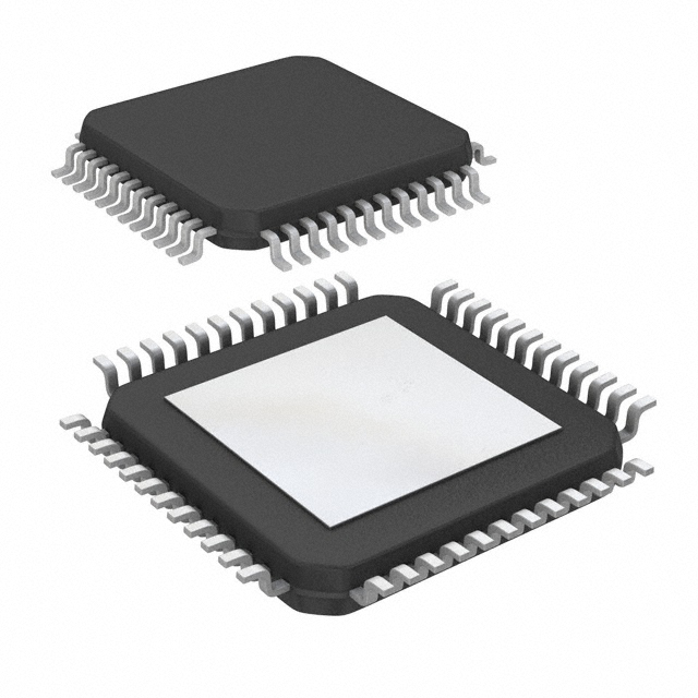
- Part No.:
- LTC3300ILXE-1#PBF
- Manufacturer:
- Analog Devices Inc.
- Category:
- Battery Management
- Package:
- 48-LQFP Exposed Pad
- Datasheet:
-
 LTC3300ILXE-1#PBF.pdf
- Description:
- IC BATT BAL MULTI 1-12C 48ELQFP
- Quantity:
- Payment:

- Shipping:

Inventory:343
Please send an inquiry. Send us your inquiry, and we will respond immediately.
Product details
Overview
LTC3300ILXE-1#PBF from Analog Devices is a fault-protected bidirectional multicell battery balancer controller IC for transformer-based active balancing of up to 6 series Li-ion or LiFePO4 cells per device, supporting input common-mode voltage up to 36V, 92% charge transfer efficiency, and daisy-chainable 1MHz SPI-compatible serial interface with 4-bit CRC.
For engineers reviewing the LTC3300ILXE-1#PBF datasheet, LTC3300ILXE-1#PBF pinout, LTC3300ILXE-1#PBF application, or LTC3300ILXE-1#PBF equivalent, this page delivers verified technical context, real-world balancing use cases, validated alternatives, and supply-ready procurement details - all grounded in the Rev. C datasheet and official package documentation.
Technical Context
The LTC3300ILXE-1#PBF implements synchronous flyback topology with independent primary and secondary gate drivers (G1P–G6P and G1S–G6S), precision current sensing on both windings (I1P–I6P, I1S–I6S), and programmable maximum on-time via RTONP/RTONS resistors. It supports two operational modes: single-transformer (CTRL = VREG) and multi-transformer (CTRL = V–).
Its level-shifting serial interface enables true galvanically isolated daisy-chaining without optocouplers - CSBI/SCKI/SDI inputs accept signals referenced to local V– while CSBO/SCKO/SDOI outputs drive the next device's inputs - enabling >1000V battery stacks with concurrent cell-by-cell balancing across all LTC3300-1 devices in the chain.
Key Specifications
| Parameter | Value and Actual Design Meaning |
|---|---|
| Cell Count | Balances up to 6 series-connected Li-ion/LiFePO4 cells per IC; scalable to >1000V via daisy-chained devices. |
| Charge Transfer Efficiency | Up to 92% at 3.6V/cell and 2.5A balancing current - directly reduces thermal load and extends balancing runtime. |
| Serial Interface | 1MHz daisy-chainable SPI with 4-bit CRC error checking and built-in watchdog timer (1.5s timeout) - ensures robust communication in noisy high-voltage battery systems. |
| Operating Temperature | –40°C to +125°C junction range - qualified for automotive and industrial energy storage applications. |
| Package | 48-lead (7mm × 7mm) plastic eLQFP with exposed V– pad - provides low θJA = 20.46°C/W for thermal management in dense BMS layouts. |
| Fault Protection | Includes overvoltage shutdown, cyclic redundancy check (CRC), readback verification, volt-second clamping, and thermal shutdown at 155°C with 10°C hysteresis. |
| Current Sensing Accuracy | VPEAK_P = 50mV ±1.7% matching across all 6 channels; VPEAK_S = 50mV ±0.5% matching - enables precise, consistent balancing current control. |
Pinout & Package
Package: 48-lead (7mm × 7mm) plastic eLQFP (LXE), exposed pad connected to V–, rated for –40°C to +125°C operation.
| Pin/Terminal | Circuit Role | Design Meaning |
|---|---|---|
| G1P–G6P (Pins 23,26,29,32,35,38) | Primary-side NMOS gate drivers | Drive external FETs in series with transformer primaries paralleling cells C1–C6; support bidirectional energy flow during charge/discharge balancing. |
| I1P–I6P (Pins 22,25,28,31,34,37) | Primary winding current sense inputs | Measure peak/zero current on primary side with 50mV ±1.7% matching - critical for accurate per-cell balancing current regulation. |
| G1S–G6S (Pins 1,3,5,7,9,11) | Secondary-side NMOS gate drivers | In multi-transformer mode, drive FETs on secondary windings; in single-transformer mode (CTRL = VREG), only G1S is active - others are NC or tied to V–. |
| I1S–I6S (Pins 2,4,6,8,10,12) | Secondary winding current sense inputs | Enable high-accuracy current monitoring on secondary side with 50mV ±0.5% matching - essential for safe, efficient inter-cell energy transfer. |
| CSBI/SCKI/SDI (Pins 16,17,18) | Level-shifted serial input interface | Accept logic signals referenced to local V–; enable optocoupler-free daisy chaining when VMODE = V– - eliminates isolation components and board space. |
| CSBO/SCKO/SDOI (Pins 45,44,43) | Level-shifted serial output interface | Drive next device's CSBI/SCKI/SDI with rail-to-rail swing - maintains signal integrity across long chains without repeaters. |
| RTONP/RTONS (Pins 14,13) | Max on-time programming inputs | Resistor-to-V– sets tONP|MAX = 7.2µs (±1%) and tONS|MAX = 1.2µs (±1%) - prevents destructive current runaway during current-sense resistor faults. |
| WDT (Pin 20) | Watchdog timer output | Precision current source (80µA typ.) pulls low during valid communication/balancing; goes high after 1.5s timeout - forces all balancers off on command loss or fault. |
Key Features
| Feature | Design Value |
|---|---|
| Bidirectional synchronous flyback architecture | Enables energy transfer both from higher- to lower-voltage cells (discharge balancing) and vice versa (charge balancing), minimizing total balancing time and power dissipation. |
| Daisy-chainable 1MHz serial interface with 4-bit CRC | Eliminates need for optocouplers or isolators in >1000V battery stacks - reduces BOM cost, PCB area, and failure points while maintaining deterministic timing. |
| Integrated precision current sensing (±0.5% matching on secondary) | Ensures uniform balancing current distribution across all 6 cells - prevents over-stressing individual cells and improves pack lifetime. |
| Fault protection with readback and CRC validation | Allows full register verification after write commands - confirms configuration integrity before initiating balancing, preventing unsafe operation due to corrupted data. |
| Exposed-pad eLQFP package (θJA = 20.46°C/W) | Provides superior thermal performance vs. QFN variant - supports sustained 10A balancing currents in compact, convection-cooled BMS modules. |
| AEC-Q100 qualified (Grade 1) | Validated for automotive battery systems including EVs and plug-in HEVs - meets stringent reliability, ESD, and temperature cycling requirements. |
Applications
| Electric Vehicle Battery Packs | Grid-Scale Energy Storage Systems |
|---|---|
Use Scenario: Balancing 12–24 series Li-ion cells in traction battery modules to maintain SOC uniformity across 400–800V DC stacks. IC Role / Device Role / Timing Role: LTC3300ILXE-1#PBF acts as the core balancing controller per 6-cell sub-stack, coordinating with LTC680x monitors and executing bidirectional transfers at up to 10A. Use Value: Reduces pack-level capacity loss from cell imbalance by >95% over 1000 cycles; enables extended vehicle range and warranty compliance. |
Use Scenario: Active balancing in 48–96-cell lithium iron phosphate (LiFePO4) strings used in commercial UPS and renewable microgrids. IC Role / Device Role / Timing Role: LTC3300ILXE-1#PBF manages per-sub-stack balancing under wide ambient temperature swings (–25°C to +60°C), leveraging its –40°C to +125°C rating. Use Value: Extends system lifetime by 30%+ versus passive balancing; supports 15-year deployments with <1% annual capacity degradation. |
| High-Power Industrial UPS | Medical Portable Power Systems |
Use Scenario: Maintaining voltage alignment across 16–32 series Li-ion cells in mission-critical hospital-grade UPS units requiring zero downtime. IC Role / Device Role / Timing Role: LTC3300ILXE-1#PBF operates in fault-protected mode with CRC-checked commands and thermal shutdown - ensuring fail-safe behavior during grid outages. Use Value: Guarantees >99.999% uptime by preventing single-cell failures from cascading into full-system shutdown. |
Use Scenario: Compact, lightweight balancing in portable defibrillators and infusion pumps using 4–8 series Li-ion cells. IC Role / Device Role / Timing Role: LTC3300ILXE-1#PBF enables ultra-low quiescent current (7µA at C1) and fast wake-up (<2ms delayed start) - preserving standby battery life. Use Value: Achieves >12-month shelf life with <1% self-discharge per month; meets IEC 60601-1 leakage and safety requirements. |
Equivalent & Alternatives
The following parts are listed as comparable options for similar bidirectional battery balancing controller applications.
| Alternative Part | Technical Difference | Application Difference | Selection Advice |
|---|---|---|---|
| TI BQ76952 | Integrated FET drivers and ADC; no external transformers required; max 16-cell support per IC; lower max balancing current (1.5A). | Targets compact, low-cost packs where transformer complexity must be avoided; not suitable for >10A balancing or >1000V stacks. | Select BQ76952 for cost-sensitive consumer or medical packs under 48V; retain LTC3300ILXE-1#PBF for high-power EV/grid systems requiring scalability and efficiency. |
| Analog Devices LTC3305 | Single-cell balancer IC; unidirectional only; no daisy-chain interface; supports up to 2A balancing current; smaller 24-pin QFN package. | Designed for low-power auxiliary battery management (e.g., 12V starter batteries); lacks fault protection features and stackability. | Choose LTC3305 only for standalone 1–3 cell balancing; LTC3300ILXE-1#PBF remains mandatory for multicell, high-reliability, bidirectional applications. |
Compared with BQ76952 and LTC3305, the LTC3300ILXE-1#PBF uniquely delivers transformer-based bidirectional balancing at up to 10A with daisy-chain scalability, making it the only option for >1000V, high-efficiency (>92%), automotive-qualified BMS architectures.
Availability
LTC3300ILXE-1#PBF is available at Aetrix Electronics and suitable for electric vehicle battery packs, grid-scale energy storage systems, and high-power industrial UPS requiring stable component supply, long-term lifecycle support, and AEC-Q100-compliant reliability.
Supply support for LTC3300ILXE-1#PBF includes scheduled delivery planning, volume procurement assistance, BOM continuity management, traceable sourcing, and lifecycle availability coordination for OEM customers, industrial embedded developers, connected-device designers, and electronics production programs.
Manufacturer
Analog Devices, Inc. is a global leader in high-performance analog, mixed-signal, and digital signal processing semiconductors, serving industrial, automotive, communications, and healthcare markets.
The LTC3300-1 product line was designed specifically for high-efficiency, fault-tolerant, transformer-coupled active balancing in large-format lithium battery systems - emphasizing scalability, safety, and thermal robustness for mission-critical energy storage.
FAQ
What is the maximum balancing current supported by the LTC3300ILXE-1#PBF?
The LTC3300ILXE-1#PBF itself does not set the balancing current limit - it controls external NMOS FETs and transformers. The datasheet confirms support for up to 10A balancing current when paired with appropriately rated external components, as demonstrated on the DC2064A demo board operating at 2.5A with 92% efficiency. Designers select MOSFETs, transformers, and sense resistors to achieve the target current.
Does the LTC3300ILXE-1#PBF require external transformers for operation?
Yes, the LTC3300ILXE-1#PBF requires external transformers for bidirectional energy transfer. It drives external NMOS FETs on both primary (cell-parallel) and secondary (multi-cell-stack) windings. The datasheet explicitly states "uses simple 2-winding transformers" and provides design guidelines for turns ratio, saturation current, and leakage inductance - no transformerless operation is supported.
How does the LTC3300ILXE-1#PBF achieve galvanic isolation between daisy-chained devices?
The LTC3300ILXE-1#PBF achieves galvanic isolation through its level-shifting serial interface: CSBI/SCKI/SDI accept logic signals referenced to local V–, while CSBO/SCKO/SDOI drive the next device's inputs with rail-to-rail swing referenced to *that* device's V–. This eliminates the need for optocouplers or isolators - confirmed in the "Daisy-Chainable Serial Interface" section of the datasheet Rev. C.
Is the LTC3300ILXE-1#PBF pin-compatible with the QFN-packaged LTC3300IUK-1#PBF?
No, the LTC3300ILXE-1#PBF (48-lead eLQFP) is not pin-compatible with the LTC3300IUK-1#PBF (48-lead QFN). Although both have 48 leads and share identical pin functions, their physical pinouts differ - the LQFP layout places pins in a perimeter arrangement with different numbering and spacing than the QFN's bottom-exposed pad configuration. PCB redesign is required for package substitution.
What fault protection mechanisms are integrated into the LTC3300ILXE-1#PBF?
The LTC3300ILXE-1#PBF integrates multiple hardware-level fault protections: overvoltage shutdown (VCELL|MAX = 5.0V), thermal shutdown (155°C), CRC error detection on serial commands, readback verification of register writes, volt-second clamping on gate drivers, and programmable maximum on-time (tONP|MAX/tONS|MAX) to prevent current runaway during current-sense resistor faults - all specified in the Rev. C datasheet Absolute Maximum Ratings and Electrical Characteristics tables.
LTC3300ILXE-1#PBF Specifications
- Product attributes
- Attribute value
- Manufacturer:
- Analog Devices Inc.
- Series:
- -
- Package/Case:
- 48-LQFP Exposed Pad
- Packaging:
- Tray
- Product Status:
- Active
- Function:
- Battery Balancer
- Battery Chemistry:
- Multi-Chemistry
- Number of Cells:
- 1 ~ 12
- Fault Protection:
- Over Temperature, Over Voltage, Short Circuit
- Interface:
- Serial
- Operating Temperature:
- -40°C ~ 125°C (TJ)
- Grade:
- -
- Qualification:
- -
- Mounting Type:
- Surface Mount
- Supplier Device Package:
- 48-eLQFP (7x7)
LTC3300ILXE-1#PBF FAQ
1.How can I place an order for LTC3300ILXE-1#PBF through Aetrix?
Please submit a Request for Quotation (RFQ) for LTC3300ILXE-1#PBF on Aetrix. Our sales agent will provide a competitive quotation and guide you through the order confirmation once you accept the terms.
2.Are the price and stock information for LTC3300ILXE-1#PBF reliable?
The price and inventory of LTC3300ILXE-1#PBF are updated periodically and may fluctuate due to market conditions. Stock and pricing data are typically refreshed every 24 hours. Quotation validity for LTC3300ILXE-1#PBF is usually 5 days.
3.What payment methods are accepted for LTC3300ILXE-1#PBF?
We accept Wire Transfer, PayPal, Credit Card, Western Union, MoneyGram, and Escrow for LTC3300ILXE-1#PBF transactions.
Note: Certain payment methods may incur a processing fee.
4.How is shipping managed for LTC3300ILXE-1#PBF?
LTC3300ILXE-1#PBF orders can be shipped via leading logistics carriers, including DHL, UPS, FedEx, TNT, or Registered Mail.
Once your LTC3300ILXE-1#PBF order is processed, you will receive an email with the shipment details and tracking number.
Note: Tracking information may take up to 24 hours to appear. Express delivery typically takes 3–5 business days.
5.How can I obtain technical support or documentation for LTC3300ILXE-1#PBF?
For technical support, including LTC3300ILXE-1#PBF datasheets, pinout diagrams, or application guidance, please contact our engineering support team. They can provide detailed documentation and assistance for your LTC3300ILXE-1#PBF requirements.
6.How does Aetrix verify that LTC3300ILXE-1#PBF is sourced from the original manufacturer or authorized distributors?
All LTC3300ILXE-1#PBF products on Aetrix are procured from qualified distributors and authorized channels. Our dedicated quality assurance team conducts strict verification, including traceability checks and, if necessary, third-party testing. This ensures that LTC3300ILXE-1#PBF meets industry standards.
7.What is the process for return or replacement of LTC3300ILXE-1#PBF?
All LTC3300ILXE-1#PBF units undergo pre-shipment inspection (PSI). If there is an issue with LTC3300ILXE-1#PBF, returns or replacements are accepted under the following conditions:
1.Quantity discrepancies, incorrect items, or visible external defects (such as breakage or corrosion), acknowledged by Aetrix.
2.The issue is reported within 90 days of delivery.
3.The LTC3300ILXE-1#PBF part is unused and in its original packaging.
Return procedure for LTC3300ILXE-1#PBF:
1.Submit a request within 90 days.
2.Obtain a Return Material Authorization (RMA) from Aetrix.
LTC3300ILXE-1#PBF Tags

-
BQ29700DSER
Texas Instruments

-
S-8241ABKMC-GBKT2G
ABLIC Inc.
-
S-8241ABPMC-GBPT2G
ABLIC Inc.

-
BQ27427YZFR
Texas Instruments

-
BQ27426YZFR
Texas Instruments

-
STC3117IJT
STMicroelectronics

-
STC3115IJT
STMicroelectronics

-
BQ76925RGER
Texas Instruments
-
NPM1100-QDAA-R
Nordic Semiconductor ASA

-
BQ27441DRZR-G1A
Texas Instruments

-
STC3115AIQT
STMicroelectronics

-
S-8252AAL-M6T1U
ABLIC Inc.
Tech Hub

A practical engineering guide to 3.3V and 5V logic compatibility, input thresholds, resistor dividers, translator ICs, MOSFET level shifting, I2C pull-ups, timing limits and power-sequencing risks.

The 74HC595 uses push-pull logic outputs, while the TPIC6B595 uses 50 V open-drain DMOS sinks for higher-power loads. This guide compares timing, current limits, 3.3 V interfacing, load wiring, thermal…

The 74HC595 converts serial data into eight stable parallel outputs. This guide covers pin functions, shift and storage timing, OE and MR behavior, drive-current limits, cascading, voltage compatibilit…

A technical comparison of level-sensitive latches and edge-triggered flip-flops, covering timing windows, setup and hold limits, master–slave operation, time borrowing, race-through, HDL inference and…

A D latch stores one bit while Enable controls when data can pass. This reference covers gate-level operation, truth tables, transparency, setup and hold timing, LE versus OE, common ICs and practical …

An SR latch stores one bit through cross-coupled feedback. This engineering reference covers NOR and NAND implementations, truth tables, forbidden-state recovery, gated operation, switch debouncing, fa…

Latch circuits retain one bit through feedback. This technical reference covers SR and D latches, truth tables, transparency, timing limits, latch-versus-flip-flop behavior, applications and common log…

An engineering guide to LED driver operation, constant-current and constant-voltage outputs, linear and switching topologies, dimming, IC selection, calculations, replacement compatibility, and fault c…

Operational amplifier guide covering op amp basics, feedback, ideal vs real op amps, common configurations, buffer circuits, offset, bias current, gain-bandwidth, slew rate, rail-to-rail limits and sel…

Jumper cables guide covering safe connection order, red and black clamp placement, final ground connection, cable gauge, length, clamp quality, copper vs CCA cables, jump starter comparison and battery…


