
 My Inquiry
 My Account


Analog Devices Inc. LTC3735EUHF#TRPBF
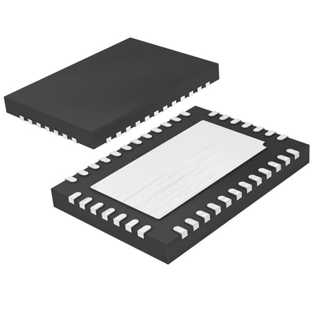
- Part No.:
- LTC3735EUHF#TRPBF
- Manufacturer:
- Analog Devices Inc.
- Category:
- Special Purpose Regulators
- Package:
- 38-WFQFN Exposed Pad
- Datasheet:
-
 LTC3735EUHF#TRPBF.pdf
- Description:
- IC REG CTRLR CPU 1OUT 38QFN
- Quantity:
- Payment:

- Shipping:

Inventory:4,936
Please send an inquiry. Send us your inquiry, and we will respond immediately.
Product details
Overview
LTC3735EUHF#TRPBF from Analog Devices (formerly Linear Technology) is a 2-phase, constant-frequency, synchronous step-down DC/DC controller for Intel mobile CPU core voltage regulation. It drives all-N-channel MOSFETs, supports 6-bit IMVP-IV VID programming (0.7V–1.708V), operates antiphase up to 550kHz, and delivers ±1% output voltage accuracy in high-current laptop/desktop power stages.
For engineers reviewing the LTC3735EUHF#TRPBF datasheet, LTC3735EUHF#TRPBF pinout, LTC3735EUHF#TRPBF application, or LTC3735EUHF#TRPBF equivalent, key selection criteria include antiphase ripple reduction, PSIB-controlled power-saving mode, stage shedding for light-load efficiency, lossless voltage positioning, and dual-input capability for load sharing across rails.
Technical Context
The LTC3735EUHF#TRPBF implements current-mode control with two independent 180° out-of-phase channels, each using cycle-by-cycle current sharing via differential sense inputs (SENSE1±/SENSE2±) and a shared ITH error amplifier output. Its antiphase operation doubles apparent switching frequency at input/output nodes, reducing RMS ripple and improving transient response without increasing per-phase losses.
It integrates Intel-compatible PSIB logic for seamless transition between fully synchronous mode (fastest transient, lowest ripple) and power-saving mode (reverse-current prevention, channel shedding), plus dedicated pins for deeper sleep (DPRSLPVR), deep sleep offset (RDPSLP), boot-up voltage setting (RBOOT), and adaptive PGOOD masking (110µs timer).
Key Specifications
| Parameter | Value and Actual Design Meaning |
|---|---|
| Output Voltage Range | 0.7V to 1.708V via 6-bit VID code; resistor-programmable at boot-up and deeper sleep state |
| Switching Frequency | 210kHz to 550kHz (programmable via FREQSET pin voltage); antiphase operation yields 2× effective ripple frequency |
| Output Accuracy | ±1% over line, load, and temperature; includes 0.6V internal reference with 0.02%/V line regulation |
| Current Sensing | Lossless differential sensing (SENSE1±/SENSE2±); max threshold 72mV; foldback current limiting activated below 70% VOUT |
| Protection Features | Overvoltage protection (±10% window), short-circuit shutdown timer with defeat option, undervoltage RUN/SS reset (3.2–4.2V) |
| Thermal Performance | θJA = 34°C/W (QFN package); junction temp rated to 125°C; exposed pad must be connected to SGND |
| Operating Temp | –40°C to +85°C ambient; validated for mobile and desktop computing environments |
Pinout & Package
Package: 38-lead (7mm × 5mm) plastic QFN with exposed signal ground pad (Pin 39). Pin pitch: 0.5mm. RoHS-compliant, lead-free finish.
| Pin/Terminal | Circuit Role | Design Meaning |
|---|---|---|
| VFB (Pin 1) | Error amplifier inverting input | Compares feedback voltage to 0.6V internal reference; sets regulation point for closed-loop control |
| DPRSLPVR (Pin 2) | Deeper sleep enable input | High signal forces deeper sleep mode; output voltage determined by RDPRSLP/RDPSLP parallel resistance |
| FREQSET (Pin 3) | Oscillator frequency control | DC voltage (0–2.4V) programs switching frequency from 210kHz to 550kHz |
| PSIB (Pin 4) | Power saving mode selector | High (>0.6V): full synchronous mode; Low (<0.6V): reverse-current prevention + optional channel shedding |
| VOA+, VOA– (Pins 5,6) | Internal op-amp inputs | Configure deep sleep offset via external resistors; support programmable AVP with 5V/µs slew rate |
| OAOUT (Pin 7) | Op-amp output | Drives RDPSLP/RDPRSLP network; enables lossless voltage positioning during sleep states |
| STP_CPUB (Pin 8) | Deep sleep trigger | Low signal activates deep sleep; output offset set by RDPSLP-to-VOA+ resistor ratio |
| SGND (Pin 9) | Signal ground reference | Common return for analog circuitry; must be routed separately from PGND and tied to exposed pad |
| SENSE1+, SENSE1– (Pins 10,11) | Channel 1 current sense inputs | Differential pair measuring voltage across RSENSE1; sets peak inductor current limit |
| SENSE2+, SENSE2– (Pins 12,13) | Channel 2 current sense inputs | Differential pair measuring voltage across RSENSE2; enables precise per-phase current sharing |
| RDPRSLP (Pin 14) | Deeper sleep resistor terminal | Connects to VOA+; forms parallel network with RDPSLP to define deeper sleep VOUT |
| RDPSLP (Pin 15) | Deep sleep offset resistor terminal | Connects to VOA+; sets percentage offset from VID voltage during deep sleep |
| RUN/SS (Pin 16) | Soft-start, run control, fault timer | Capacitor sets ramp time; <1V forces shutdown; discharge initiates latchoff during short-circuit |
| ITH (Pin 17) | Error amplifier output / compensation node | Controls current comparator thresholds; 0–2.4V range sets peak inductor current for both phases |
| RBOOT (Pin 18) | Boot-up voltage setting | Resistor to VOA+ defines output voltage during initial startup before VID takes effect |
| VID0–VID5 (Pins 19–24) | IMVP-IV voltage identification inputs | 6-bit digital interface for dynamic CPU VDD scaling; logic thresholds 0.3V/0.7V |
| BG1, BG2 (Pins 24,26) | Bottom gate drivers | 5A peak sink/source; drive N-MOSFET sources to PGND; voltage swing = 0V to PVCC |
| PGND (Pin 25) | Power ground | Return path for bottom MOSFET sources and CIN negative terminals; separate from SGND |
| PVCC (Pin 27) | Controller supply | 4.5–7V supply for logic and gate drivers; requires ≥4.7µF ceramic decoupling to PGND |
| SW1, SW2 (Pins 28,32) | Switch node connections | Connect to inductor tops; voltage swing = –0.3V to VIN; referenced to PGND |
| TG1, TG2 (Pins 29,33) | Top gate drivers | 5A peak sink/source; floating outputs referenced to SWx; voltage swing = SWx to SWx+PVCC |
| BOOST1, BOOST2 (Pins 30,34) | Bootstrap supplies | External capacitors between BOOSTx and SWx enable top MOSFET drive above VIN |
| PGOOD (Pin 35) | Power good indicator | Open-drain output active low when VOUT outside ±10%; masked for 110µs during VID/state transitions |
| MCH_PG (Pin 36) | MCH power good input | Delays exit from boot-up for 15 clock cycles after assertion; synchronizes with chipset sequencing |
| Exposed Pad (Pin 39) | Signal ground | Must be soldered to PCB and connected to SGND (Pin 9) and PGND (Pin 25) |
Key Features
| Feature | Design Value |
|---|---|
| Antiphase 2-phase operation | Doubles effective switching frequency at input/output nodes, cutting RMS capacitor ripple current and improving transient response without raising per-phase switching losses |
| Intel PSIB-compatible power saving mode | Automatically disables reverse current conduction and sheds Channel 2 under light load, eliminating gate drive and transition losses while maintaining regulation |
| Lossless voltage positioning (AVP) | Uses internal op-amp (VOA+/VOA–/OAOUT) and external resistors to implement programmable droop without current-sense resistors or additional components |
| Dual-input supply capability | Allows independent connection of Channel 1 and Channel 2 to separate input rails, enabling true load sharing and redundancy in multi-rail systems |
| Adaptive PGOOD masking | 110µs blanking window prevents false system resets during VID changes, deep sleep entry, or MCH_PG-triggered sequencing events |
Applications
| Mobile CPU Core Power | Desktop CPU VRM |
|---|---|
Use Scenario: Regulating core voltage for Intel Pentium M, Core Duo, and early Core 2 processors in thin-and-light notebooks requiring high efficiency across 0.1A–40A load range. IC Role / Device Role / Timing Role: Dual-phase synchronous buck controller managing dynamic VID updates, deep sleep transitions, and antiphase ripple cancellation. Use Value: Enables ±1% output accuracy and sub-100ns PGOOD masking to meet Intel IMVP-IV timing requirements while sustaining >90% efficiency at 20A load. | Use Scenario: High-current CPU voltage regulation in ATX desktop motherboards where thermal density and transient response are critical. IC Role / Device Role / Timing Role: 2-phase PolyPhase® controller coordinating gate drive timing, current sharing, and phase interleaving for 30A+ loads. Use Value: Antiphase operation reduces input capacitor RMS current by ~30%, allowing smaller bulk capacitance and lower ESR solutions without sacrificing stability. |
| Internet Server CPU Supply | Embedded x86 Computing Platform |
Use Scenario: Powering dual-core Xeon or Pentium D processors in 1U rack servers where airflow-limited thermal design demands high light-load efficiency. IC Role / Device Role / Timing Role: Adaptive controller implementing PSIB-driven power saving mode and DPRSLPVR-activated deeper sleep for <1W idle power. Use Value: Stage shedding cuts quiescent current by 40% and eliminates Channel 2 gate drive losses, extending server uptime during low-utilization periods. | Use Scenario: Compact x86-based industrial controllers requiring robust, long-lifecycle power management for fanless operation. IC Role / Device Role / Timing Role: Primary VRM controller supporting wide input (5–24V), extended temperature (–40°C to 85°C), and deterministic sequencing via MCH_PG and STP_CPUB. Use Value: Exposed-pad QFN package (θJA = 34°C/W) and integrated overvoltage/short-circuit protection reduce BOM count and improve field reliability without external supervision ICs. |
Equivalent & Alternatives
The following parts are listed as comparable options for similar dual-phase synchronous buck controller applications.
| Alternative Part | Technical Difference | Application Difference | Selection Advice |
|---|---|---|---|
| ISL6260CRTZ-T | Single-chip dual-phase controller with integrated MOSFET drivers; lacks PSIB pin and deeper sleep mode; fixed 300kHz/600kHz options only | Designed for Intel Pentium M platforms but does not support IMVP-IV deeper sleep states or resistor-programmable boot voltage | Select ISL6260CRTZ-T only if PSIB control and multi-state sleep sequencing are unnecessary and board space is constrained |
| RT8803GQW | Supports 6-bit VID and antiphase operation but uses external op-amp for AVP; no integrated deep sleep offset programming; max fSW = 1MHz | Targeted at newer Intel Core i-series CPUs; lacks DPRSLPVR pin and MCH_PG synchronization logic | Choose RT8803GQW when higher switching frequency is needed and deep sleep state coordination with chipset is handled externally |
Compared with ISL6260CRTZ-T and RT8803GQW, the LTC3735EUHF#TRPBF uniquely combines IMVP-IV-compliant PSIB/STP_CPUB/DPRSLPVR sequencing, on-die op-amp for lossless AVP, and resistor-programmable voltages for boot/deep-sleep states-making it irreplaceable for legacy Intel mobile platform designs requiring full specification compliance.
Availability
LTC3735EUHF#TRPBF is available at Aetrix Electronics and suitable for mobile CPU core power, desktop VRM, internet server CPU supply, and embedded x86 computing platforms requiring stable component supply, long-term lifecycle support, and guaranteed RoHS-compliant manufacturing.
Supply support for LTC3735EUHF#TRPBF includes scheduled delivery planning, volume procurement assistance, BOM continuity management, traceable sourcing, and lifecycle availability coordination for OEM customers, industrial embedded developers, connected-device designers, and electronics production programs.
Manufacturer
Analog Devices acquired Linear Technology in 2017 and maintains full technical and manufacturing continuity for all Linear power management products.
The LTC3735EUHF#TRPBF belongs to Linear's high-performance PolyPhase® controller family, engineered specifically for Intel IMVP-IV-compliant mobile and desktop CPU voltage regulation with emphasis on antiphase efficiency, multi-state sleep sequencing, and lossless voltage positioning.
FAQ
What is the maximum supported switching frequency for the LTC3735EUHF#TRPBF?
The LTC3735EUHF#TRPBF supports a programmable switching frequency range of 210kHz to 550kHz via the FREQSET pin voltage (0V to 2.4V). At 550kHz, each phase operates at that frequency while antiphase interleaving yields an effective 1.1MHz ripple frequency at input and output capacitors-critical for minimizing capacitor size and ESR in space-constrained mobile designs. The LTC3735EUHF#TRPBF datasheet specifies 550kHz as the absolute maximum nominal frequency under recommended operating conditions.
How does the PSIB pin affect operation mode in the LTC3735EUHF#TRPBF?
The PSIB pin on the LTC3735EUHF#TRPBF selects between two distinct operational modes: when pulled above 0.6V, both channels operate in fully synchronous mode with reverse current allowed for fastest transient response and lowest output ripple; when pulled below 0.6V, reverse current is prevented and Channel 2 may be shed under light load to maximize efficiency. This Intel-compatible behavior is fundamental to the LTC3735EUHF#TRPBF's power-saving architecture and directly impacts thermal design and light-load efficiency curves.
Can the LTC3735EUHF#TRPBF be used with non-Intel CPUs or non-IMVP-IV platforms?
While the LTC3735EUHF#TRPBF was designed for Intel IMVP-IV mobile CPUs and includes VID decoding, PSIB, DPRSLPVR, and STP_CPUB logic optimized for that ecosystem, it can be adapted to non-Intel applications by fixing VID lines to static values, tying PSIB high for continuous synchronous operation, and disabling deeper sleep functions. However, its full feature set-including adaptive PGOOD masking, lossless AVP, and stage shedding-is only leveraged in IMVP-IV-compliant systems. For generic dual-phase buck control, the LTC3735EUHF#TRPBF remains functional but underutilized.
What is the purpose of the exposed pad (Pin 39) on the LTC3735EUHF#TRPBF QFN package?
The exposed pad (Pin 39) on the LTC3735EUHF#TRPBF is designated as signal ground (SGND) and must be soldered to the PCB and electrically connected to both Pin 9 (SGND) and Pin 25 (PGND). This connection provides critical thermal dissipation (reducing θJA from 85°C/W to 34°C/W) and establishes a low-impedance return path for sensitive analog circuitry including the error amplifier and current comparators. Failure to properly connect the exposed pad will degrade thermal performance and may cause regulation instability or premature thermal shutdown in the LTC3735EUHF#TRPBF.
Does the LTC3735EUHF#TRPBF support dual-input operation, and how is it implemented?
Yes, the LTC3735EUHF#TRPBF supports dual-input supply capability: Channel 1 (SW1/TG1/BG1) and Channel 2 (SW2/TG2/BG2) can be connected to separate input rails (e.g., +12V and +5V), enabling true load sharing across power domains. This is implemented through independent high-side and low-side driver stages with isolated bootstrap supplies (BOOST1/BOOST2) and current sensing (SENSE1±/SENSE2±). The LTC3735EUHF#TRPBF's current-mode architecture inherently balances current between phases even with unequal input voltages, making it suitable for redundant or hybrid power architectures.
LTC3735EUHF#TRPBF Specifications
- Product attributes
- Attribute value
- Manufacturer:
- Analog Devices Inc.
- Series:
- -
- Package/Case:
- 38-WFQFN Exposed Pad
- Packaging:
- Tape & Reel (TR)
- Product Status:
- Active
- Applications:
- Controller, Intel Mobile CPU
- Voltage - Input:
- -
- Number of Outputs:
- 1
- Voltage - Output:
- 0.7V ~ 1.71V
- Operating Temperature:
- -40°C ~ 85°C
- Grade:
- -
- Qualification:
- -
- Mounting Type:
- Surface Mount
- Supplier Device Package:
- 38-QFN (5x7)
LTC3735EUHF#TRPBF FAQ
1.How can I place an order for LTC3735EUHF#TRPBF through Aetrix?
Please submit a Request for Quotation (RFQ) for LTC3735EUHF#TRPBF on Aetrix. Our sales agent will provide a competitive quotation and guide you through the order confirmation once you accept the terms.
2.Are the price and stock information for LTC3735EUHF#TRPBF reliable?
The price and inventory of LTC3735EUHF#TRPBF are updated periodically and may fluctuate due to market conditions. Stock and pricing data are typically refreshed every 24 hours. Quotation validity for LTC3735EUHF#TRPBF is usually 5 days.
3.What payment methods are accepted for LTC3735EUHF#TRPBF?
We accept Wire Transfer, PayPal, Credit Card, Western Union, MoneyGram, and Escrow for LTC3735EUHF#TRPBF transactions.
Note: Certain payment methods may incur a processing fee.
4.How is shipping managed for LTC3735EUHF#TRPBF?
LTC3735EUHF#TRPBF orders can be shipped via leading logistics carriers, including DHL, UPS, FedEx, TNT, or Registered Mail.
Once your LTC3735EUHF#TRPBF order is processed, you will receive an email with the shipment details and tracking number.
Note: Tracking information may take up to 24 hours to appear. Express delivery typically takes 3–5 business days.
5.How can I obtain technical support or documentation for LTC3735EUHF#TRPBF?
For technical support, including LTC3735EUHF#TRPBF datasheets, pinout diagrams, or application guidance, please contact our engineering support team. They can provide detailed documentation and assistance for your LTC3735EUHF#TRPBF requirements.
6.How does Aetrix verify that LTC3735EUHF#TRPBF is sourced from the original manufacturer or authorized distributors?
All LTC3735EUHF#TRPBF products on Aetrix are procured from qualified distributors and authorized channels. Our dedicated quality assurance team conducts strict verification, including traceability checks and, if necessary, third-party testing. This ensures that LTC3735EUHF#TRPBF meets industry standards.
7.What is the process for return or replacement of LTC3735EUHF#TRPBF?
All LTC3735EUHF#TRPBF units undergo pre-shipment inspection (PSI). If there is an issue with LTC3735EUHF#TRPBF, returns or replacements are accepted under the following conditions:
1.Quantity discrepancies, incorrect items, or visible external defects (such as breakage or corrosion), acknowledged by Aetrix.
2.The issue is reported within 90 days of delivery.
3.The LTC3735EUHF#TRPBF part is unused and in its original packaging.
Return procedure for LTC3735EUHF#TRPBF:
1.Submit a request within 90 days.
2.Obtain a Return Material Authorization (RMA) from Aetrix.
LTC3735EUHF#TRPBF Tags

-
TPS51206DSQR
Texas Instruments

-
TPS51200DRCR
Texas Instruments
-
TPS51200DRCT
Texas Instruments

-
TPS62740DSSR
Texas Instruments

-
TPS51100DGQR
Texas Instruments

-
NCP51200MNTXG
onsemi
-
NCP51400MNTXG
onsemi

-
RT9026GSP
Richtek USA Inc.

-
LP2998MRX/NOPB
Texas Instruments
-
TPS51200QDRCRQ1
Texas Instruments

-
DPA423GN-TL
Power Integrations
-
LM10011SD/NOPB
Texas Instruments
Tech Hub

A practical engineering guide to 3.3V and 5V logic compatibility, input thresholds, resistor dividers, translator ICs, MOSFET level shifting, I2C pull-ups, timing limits and power-sequencing risks.

The 74HC595 uses push-pull logic outputs, while the TPIC6B595 uses 50 V open-drain DMOS sinks for higher-power loads. This guide compares timing, current limits, 3.3 V interfacing, load wiring, thermal…

The 74HC595 converts serial data into eight stable parallel outputs. This guide covers pin functions, shift and storage timing, OE and MR behavior, drive-current limits, cascading, voltage compatibilit…

A technical comparison of level-sensitive latches and edge-triggered flip-flops, covering timing windows, setup and hold limits, master–slave operation, time borrowing, race-through, HDL inference and…

A D latch stores one bit while Enable controls when data can pass. This reference covers gate-level operation, truth tables, transparency, setup and hold timing, LE versus OE, common ICs and practical …

An SR latch stores one bit through cross-coupled feedback. This engineering reference covers NOR and NAND implementations, truth tables, forbidden-state recovery, gated operation, switch debouncing, fa…

Latch circuits retain one bit through feedback. This technical reference covers SR and D latches, truth tables, transparency, timing limits, latch-versus-flip-flop behavior, applications and common log…

An engineering guide to LED driver operation, constant-current and constant-voltage outputs, linear and switching topologies, dimming, IC selection, calculations, replacement compatibility, and fault c…

Operational amplifier guide covering op amp basics, feedback, ideal vs real op amps, common configurations, buffer circuits, offset, bias current, gain-bandwidth, slew rate, rail-to-rail limits and sel…

Jumper cables guide covering safe connection order, red and black clamp placement, final ground connection, cable gauge, length, clamp quality, copper vs CCA cables, jump starter comparison and battery…


