
 My Inquiry
 My Account


Analog Devices Inc. LTC4041EUFD#TRPBF
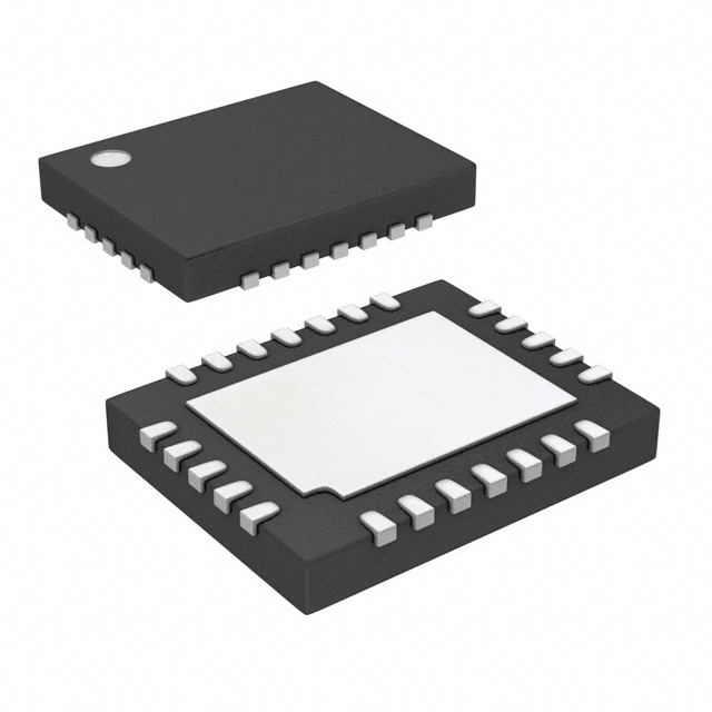
- Part No.:
- LTC4041EUFD#TRPBF
- Manufacturer:
- Analog Devices Inc.
- Category:
- Battery Management
- Package:
- 24-WFQFN Exposed Pad
- Datasheet:
-
 LTC4041EUFD#TRPBF.pdf
- Description:
- IC BATT PWR MGMT MULTI 1C 24QFN
- Quantity:
- Payment:

- Shipping:

Inventory:1,086
Please send an inquiry. Send us your inquiry, and we will respond immediately.
Product details
Overview
LTC4041EUFD#TRPBF from Analog Devices is a 2.5A supercapacitor backup power manager IC for 2.9V–5.5V supply rails, integrating a synchronous step-down charger and reverse-operating step-up backup regulator. It supports single or dual-series supercapacitors, delivers up to 2.5A backup current, features internal balancing, programmable charge voltage (via CAPFB), and operates in a thermally enhanced 24-lead 4mm × 5mm QFN package.
For engineers reviewing the LTC4041EUFD#TRPBF datasheet, LTC4041EUFD#TRPBF pinout, LTC4041EUFD#TRPBF application, or LTC4041EUFD#TRPBF equivalent, key selection criteria include input current limiting (25mV CLN threshold), seamless switchover timing, supercapacitor balancing accuracy (±1% VSCAP/2), boost output regulation (0.8V BSTFB reference), and OVP protection up to 6.8V.
Technical Context
The LTC4041EUFD#TRPBF implements a dual-mode synchronous buck-boost architecture: the buck stage charges supercapacitors at 2.25MHz with 120mΩ/130mΩ NMOS/PMOS RDS(on), while the boost stage delivers regulated VSYS from SCAP with 70mΩ/75mΩ switches and 1.125MHz switching. Its IMON amplifier (gain = 32) enables load-prioritized current limiting by monitoring VIN–CLN differential voltage.
It integrates autonomous mode control via PFI comparator (1.19V threshold, 40mV hysteresis), SYSGD comparator (0.74V RSTFB threshold), and CAPGD status (92.5% VCHG rising threshold). The internal balancer maintains ±1% balance across two-series supercapacitors without external resistors, sinking/sourcing 50mA at 5V VSCAP.
Key Specifications
| Parameter | Value and Actual Design Meaning |
|---|---|
| Input Voltage Range | 2.9V to 5.5V - supports standard 3.3V/5V system rails without level-shifting. |
| Backup Boost Output Range | 2.7V to 5.0V - programmable via BSTFB resistor divider for precise system voltage matching. |
| Charge Current Accuracy | ±5% typical - achieved via PROG pin servo (0.800V ±12mV) and hPROG = 2500 mA/mA ratio. |
| Supercapacitor Balancing | ±1% balance point (VBAL = 49–51% of VSCAP) - eliminates need for external balancing resistors. |
| OVP Threshold | 6.4V typical (6.0–6.8V) - protects device from transients using external 6.2k OVSNS resistor. |
| Quiescent Current (Backup Sleep) | 75–150µA VSYS + 1–2µA SCAP - enables multi-day hold-up with low-leakage supercapacitors. |
| Switching Frequencies | Buck: 2.25MHz (±12.5%), Boost: 1.125MHz (±12.5%) - enables compact 2.2µH inductor and low-profile layout. |
Pinout & Package
Package: 24-lead 4mm × 5mm × 0.75mm plastic QFN with exposed thermal pad (Pin 25 = GND, must be soldered).
| Pin/Terminal | Circuit Role | Design Meaning |
|---|---|---|
| VSYS (Pins 1, 24) | System output rail | Delivers power to load from VIN (normal mode) or SCAP (backup mode); requires ≥100µF low-ESR ceramic bypass. |
| PROG (Pin 2) | Charge current programming | 0.8V servo node; sets full-scale charge current as ICHG = 2000V/RPROG (e.g., 2kΩ → 1A). |
| IMON (Pin 3) | Input current monitor | Voltage = 32 × (VIN – CLN); clamps at 0.8V to reduce charge current when system load exceeds RS limit. |
| CHGEN (Pin 4) | Charger enable/disable | Logic low (≤0.4V) enables buck charging; high (>1.2V) disables - prevents unintended charging during debug. |
| BSTEN (Pin 5) | Boost backup enable/disable | Logic low enables backup mode; high disables - allows controlled shutdown of backup path. |
| CLN (Pin 7) | Negative sense terminal | Forms current-sense pair with VIN; 25mV drop across RS sets max input current (e.g., 25mΩ → 1A). |
| CAPFB (Pin 12) | Supercapacitor voltage feedback | 0.8V servo node; external divider sets VCHG = 0.8V × (1 + R1/R2) - e.g., 3.3V requires R1/R2 ≈ 3.125. |
| BSTFB (Pin 18) | Boost output feedback | 0.8V servo node; external divider programs VSYS = 0.8V × (1 + R1/R2) - independent of CAPFB setting. |
| PFI (Pin 19) | Power-fail input | 1.19V comparator threshold; falling edge triggers backup switchover - sets minimum input voltage before backup activation. |
| CAPSEL (Pin 20) | Capacitor stack configuration | Ground = single supercap; >1.2V = two in series - configures balancer and fault thresholds accordingly. |
| SW (Pins 21, 22) | Power switch node | Shared buck/boost switching node; connects to inductor (2.2µH typical) between SCAP and SW. |
| SCAP (Pin 23) | Supercapacitor connection | Connects to top of single cap or two-cap stack; voltage range up to 5.4V - defines energy storage interface. |
Key Features
| Feature | Design Value |
|---|---|
| Integrated supercapacitor balancer | Active balancing for two-series caps with ±1% accuracy and no external resistors - eliminates leakage mismatch drift. |
| Load-prioritized input current limiting | IMON amplifier dynamically reduces charge current to maintain system load priority - avoids brownout under heavy load. |
| Seamless backup switchover | Automatic transition with <200µs delay and no VSYS droop - preserves operation of real-time clocks, SRAM, or FPGA configuration. |
| Programmable minimum backup time | CPF capacitor sets tMIN-BACKUP ≥2.2ms - prevents oscillation during marginal input voltage conditions. |
| Input overvoltage protection | OVSNS pin enables external FET cutoff at 6.4V (typical) - protects IC from >60V transients without external TVS. |
| Low-quiescent backup sleep mode | 75µA VSYS + 1µA SCAP total - extends hold-up time by >3× vs active backup mode for battery-free systems. |
Applications
| Industrial Power Meters | Servers & SSDs |
|---|---|
|
Use Scenario: Maintains real-time clock and metering data during AC mains interruption. IC Role / Device Role / Timing Role: Backup power manager providing uninterrupted 3.3V/5V to RTC, flash memory, and communication ICs. Use Value: Enables >30-second hold-up with 10F supercapacitor, meeting ANSI C12.1 and IEC 62053-21 requirements. |
Use Scenario: Preserves DRAM contents and SSD controller state during unexpected power loss. IC Role / Device Role / Timing Role: High-current (2.5A) backup source delivering stable VSYS during write-cache flush. Use Value: Prevents data corruption by sustaining 5V @ 2A for ≥100ms using dual 10F supercapacitors in series. |
| Industrial Alarms & PLCs | Ride-Through "Dying Gasp" Supplies |
|
Use Scenario: Powers alarm siren and sensor interface after main supply failure in hazardous environments. IC Role / Device Role / Timing Role: Fault-tolerant backup IC with CAPFLT monitoring and automatic recharge. Use Value: Detects supercapacitor overvoltage (2.7V/cell) and undervoltage (–20mV) to prevent catastrophic failure. |
Use Scenario: Provides last-cycle power to microcontroller for safe shutdown and nonvolatile logging. IC Role / Device Role / Timing Role: Low-quiescent (75µA) backup supervisor enabling multi-hour standby on supercapacitor. Use Value: Reduces required capacitance by 40% vs discrete solutions due to 1µA SCAP sleep current. |
Equivalent & Alternatives
The following parts are listed as comparable options for similar supercapacitor backup management applications.
| Alternative Part | Technical Difference | Application Difference | Selection Advice |
|---|---|---|---|
| MAX32664AELB+ | Lower 1.5A max backup current; integrated fuel gauge; I²C interface; no internal balancer. | Targeted at wearable/portable devices with battery + supercap hybrid; lacks dual-cap support. | Select for space-constrained designs needing SoC-level telemetry, not industrial dual-cap backup. |
| BQ33100EVM-657 | Standalone balancer + external DC/DC; 3A boost; no integrated charger; requires external MOSFETs. | Used in high-reliability telecom systems where redundancy and field-replaceable modules are critical. | Select when modular design, MIL-STD-810G vibration tolerance, or >3A backup current is mandatory. |
Compared with MAX32664AELB+ and BQ33100EVM-657, the LTC4041EUFD#TRPBF uniquely integrates charger, balancer, and bidirectional converter in one QFN - eliminating 12 external components and reducing PCB area by 35% while supporting both single/dual supercapacitor topologies.
Availability
LTC4041EUFD#TRPBF is available at Aetrix Electronics and suitable for industrial power meters, server SSDs, PLCs, and ride-through "dying gasp" supplies requiring stable component supply, long-term lifecycle assurance, and automotive-grade reliability screening.
Supply support for LTC4041EUFD#TRPBF includes scheduled delivery planning, volume procurement assistance, BOM continuity management, traceable sourcing, and lifecycle availability coordination for OEM customers, industrial embedded developers, connected-device designers, and electronics production programs.
Manufacturer
Analog Devices, Inc. is a global leader in high-performance analog, mixed-signal, and digital signal processing semiconductors, serving industrial, automotive, communications, and healthcare markets.
The LTC4041EUFD#TRPBF belongs to Analog Devices' Power Management portfolio, designed specifically for robust, maintenance-free backup power in mission-critical infrastructure where battery replacement is impractical or unsafe.
FAQ
What is the maximum supercapacitor voltage supported by the LTC4041EUFD#TRPBF?
The LTC4041EUFD#TRPBF supports a maximum supercapacitor voltage of 5.4V on the SCAP pin. When configured for two-series supercapacitors (CAPSEL high), its internal balancer enforces ≤2.7V per cell to prevent overvoltage damage, with ±55mV hysteresis on the top/bottom cell thresholds.
How does the LTC4041EUFD#TRPBF prioritize system load versus supercapacitor charging?
The LTC4041EUFD#TRPBF uses the IMON amplifier to monitor input current via the VIN–CLN differential. When system load demand approaches the programmed input current limit (set by RS), the IMON voltage rises and automatically reduces charge current to preserve VSYS stability - ensuring the load is always powered first.
Can the LTC4041EUFD#TRPBF operate with only one supercapacitor?
Yes, the LTC4041EUFD#TRPBF fully supports single-supercapacitor configurations. Tie CAPSEL to GND to disable the balancer and configure fault thresholds for 0–5.4V SCAP range. The internal balancer is automatically disabled, and CAPFLT monitors total SCAP voltage against 2.7V overvoltage and –20mV undervoltage limits.
What is the purpose of the CPF pin on the LTC4041EUFD#TRPBF?
The CPF pin on the LTC4041EUFD#TRPBF programs the minimum backup time (tMIN-BACKUP) using an external capacitor. With CCPF = 1nF, tMIN-BACKUP ≥2.2ms - preventing spurious backup mode toggling during brief input dips and ensuring reliable hold-up initiation.
Does the LTC4041EUFD#TRPBF require external MOSFETs for input disconnect?
Yes, the LTC4041EUFD#TRPBF requires external N-channel MOSFETs driven by IGATE for input disconnect during backup mode. One FET isolates VIN from the input supply (optional OVP), and a second FET disconnects VIN from VSYS - ensuring zero backfeed and clean system isolation.
LTC4041EUFD#TRPBF Specifications
- Product attributes
- Attribute value
- Manufacturer:
- Analog Devices Inc.
- Series:
- -
- Package/Case:
- 24-WFQFN Exposed Pad
- Packaging:
- Tape & Reel (TR)
- Product Status:
- Active
- Function:
- Power Management
- Battery Chemistry:
- Multi-Chemistry
- Number of Cells:
- 1
- Fault Protection:
- Over Voltage
- Interface:
- -
- Operating Temperature:
- -40°C ~ 125°C (TJ)
- Grade:
- -
- Qualification:
- -
- Mounting Type:
- Surface Mount
- Supplier Device Package:
- 24-QFN (4x5)
LTC4041EUFD#TRPBF FAQ
1.How can I place an order for LTC4041EUFD#TRPBF through Aetrix?
Please submit a Request for Quotation (RFQ) for LTC4041EUFD#TRPBF on Aetrix. Our sales agent will provide a competitive quotation and guide you through the order confirmation once you accept the terms.
2.Are the price and stock information for LTC4041EUFD#TRPBF reliable?
The price and inventory of LTC4041EUFD#TRPBF are updated periodically and may fluctuate due to market conditions. Stock and pricing data are typically refreshed every 24 hours. Quotation validity for LTC4041EUFD#TRPBF is usually 5 days.
3.What payment methods are accepted for LTC4041EUFD#TRPBF?
We accept Wire Transfer, PayPal, Credit Card, Western Union, MoneyGram, and Escrow for LTC4041EUFD#TRPBF transactions.
Note: Certain payment methods may incur a processing fee.
4.How is shipping managed for LTC4041EUFD#TRPBF?
LTC4041EUFD#TRPBF orders can be shipped via leading logistics carriers, including DHL, UPS, FedEx, TNT, or Registered Mail.
Once your LTC4041EUFD#TRPBF order is processed, you will receive an email with the shipment details and tracking number.
Note: Tracking information may take up to 24 hours to appear. Express delivery typically takes 3–5 business days.
5.How can I obtain technical support or documentation for LTC4041EUFD#TRPBF?
For technical support, including LTC4041EUFD#TRPBF datasheets, pinout diagrams, or application guidance, please contact our engineering support team. They can provide detailed documentation and assistance for your LTC4041EUFD#TRPBF requirements.
6.How does Aetrix verify that LTC4041EUFD#TRPBF is sourced from the original manufacturer or authorized distributors?
All LTC4041EUFD#TRPBF products on Aetrix are procured from qualified distributors and authorized channels. Our dedicated quality assurance team conducts strict verification, including traceability checks and, if necessary, third-party testing. This ensures that LTC4041EUFD#TRPBF meets industry standards.
7.What is the process for return or replacement of LTC4041EUFD#TRPBF?
All LTC4041EUFD#TRPBF units undergo pre-shipment inspection (PSI). If there is an issue with LTC4041EUFD#TRPBF, returns or replacements are accepted under the following conditions:
1.Quantity discrepancies, incorrect items, or visible external defects (such as breakage or corrosion), acknowledged by Aetrix.
2.The issue is reported within 90 days of delivery.
3.The LTC4041EUFD#TRPBF part is unused and in its original packaging.
Return procedure for LTC4041EUFD#TRPBF:
1.Submit a request within 90 days.
2.Obtain a Return Material Authorization (RMA) from Aetrix.
LTC4041EUFD#TRPBF Tags

-
BQ29700DSER
Texas Instruments

-
S-8241ABKMC-GBKT2G
ABLIC Inc.
-
S-8241ABPMC-GBPT2G
ABLIC Inc.

-
BQ27427YZFR
Texas Instruments

-
BQ27426YZFR
Texas Instruments

-
STC3117IJT
STMicroelectronics

-
STC3115IJT
STMicroelectronics

-
BQ76925RGER
Texas Instruments
-
NPM1100-QDAA-R
Nordic Semiconductor ASA

-
BQ27441DRZR-G1A
Texas Instruments

-
STC3115AIQT
STMicroelectronics

-
S-8252AAL-M6T1U
ABLIC Inc.
Tech Hub

A practical engineering guide to 3.3V and 5V logic compatibility, input thresholds, resistor dividers, translator ICs, MOSFET level shifting, I2C pull-ups, timing limits and power-sequencing risks.

The 74HC595 uses push-pull logic outputs, while the TPIC6B595 uses 50 V open-drain DMOS sinks for higher-power loads. This guide compares timing, current limits, 3.3 V interfacing, load wiring, thermal…

The 74HC595 converts serial data into eight stable parallel outputs. This guide covers pin functions, shift and storage timing, OE and MR behavior, drive-current limits, cascading, voltage compatibilit…

A technical comparison of level-sensitive latches and edge-triggered flip-flops, covering timing windows, setup and hold limits, master–slave operation, time borrowing, race-through, HDL inference and…

A D latch stores one bit while Enable controls when data can pass. This reference covers gate-level operation, truth tables, transparency, setup and hold timing, LE versus OE, common ICs and practical …

An SR latch stores one bit through cross-coupled feedback. This engineering reference covers NOR and NAND implementations, truth tables, forbidden-state recovery, gated operation, switch debouncing, fa…

Latch circuits retain one bit through feedback. This technical reference covers SR and D latches, truth tables, transparency, timing limits, latch-versus-flip-flop behavior, applications and common log…

An engineering guide to LED driver operation, constant-current and constant-voltage outputs, linear and switching topologies, dimming, IC selection, calculations, replacement compatibility, and fault c…

Operational amplifier guide covering op amp basics, feedback, ideal vs real op amps, common configurations, buffer circuits, offset, bias current, gain-bandwidth, slew rate, rail-to-rail limits and sel…

Jumper cables guide covering safe connection order, red and black clamp placement, final ground connection, cable gauge, length, clamp quality, copper vs CCA cables, jump starter comparison and battery…


