
 My Inquiry
 My Account


Analog Devices Inc. LTC4331HUFD#PBF
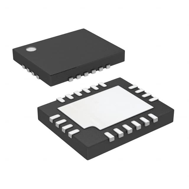
- Part No.:
- LTC4331HUFD#PBF
- Manufacturer:
- Analog Devices Inc.
- Category:
- Specialized ICs
- Package:
- 20-WFQFN Exposed Pad
- Datasheet:
-
 LTC4331HUFD#PBF.pdf
- Description:
- IC DIFFERENTIAL LINK 20QFN
- Quantity:
- Payment:

- Shipping:

Inventory:3,679
Please send an inquiry. Send us your inquiry, and we will respond immediately.
Product details
Overview
LTC4331HUFD#PBF from Analog Devices is an SMBus 3.0–compatible I2C slave device extender IC designed for high-noise industrial environments. It extends I2C/SMBus-including SMBALERT and a control signal-over a single twisted-pair differential link up to 1200 m, supports up to 1 MHz Fast-mode Plus (Fm+) local SCL, features ±60 V fault-protected transceiver pins (A/B), and operates across –40°C to +125°C.
For engineers reviewing the LTC4331HUFD#PBF datasheet, LTC4331HUFD#PBF pinout, LTC4331HUFD#PBF application, or LTC4331HUFD#PBF equivalent, key selection considerations include differential link robustness (±15 V common mode, ±40 kV ESD), independent local/remote bus timing, I2C address sharing capability, and support for clock-stretching–enabled masters in extended topology deployments.
Technical Context
The LTC4331HUFD#PBF implements a bidirectional, packetized I2C extension architecture using an RS485-compliant differential transceiver with ±60 V fault protection on A/B pins and ±15 V extended common mode range. It operates in two mutually exclusive modes: local (REMOTE = 0) as an SMBus-compatible slave with configurable I2C timing (Fm+/Fm/Sm), and remote (REMOTE = 1) as a master replicating local transactions on the far-end bus.
Link baud rate is selected via SPEED1/SPEED2 (9 speed indices), with SLO enabling slew-rate limiting for EMI reduction-valid only for Speed Index 0 or 1. Propagation delays (e.g., tALT_PROP, tCTRL_PROP) scale linearly with Speed Factor (SF), and local SCL frequencies up to 2000 kHz are accepted but effective throughput is capped at 1000 kHz due to protocol overhead and clock-stretching constraints.
Key Specifications
| Parameter | Value and Actual Design Meaning |
|---|---|
| Operating Temperature | –40°C to +125°C - qualified for harsh industrial environments including motor drives and factory automation nodes. |
| Supply Voltage Range | VCC: 3 V to 5.5 V; VL: 1.62 V to 5.5 V - supports mixed-voltage system integration with 3.3 V or 5 V logic domains. |
| I2C Local Clock Rate | Up to 1000 kHz Fm+ - enables high-speed local bus operation while maintaining compatibility with legacy Fm/Sm devices. |
| Differential Link Protection | ±60 V fault tolerance on A/B pins - prevents damage from ground loop surges or cable ESD events in long-line installations. |
| ESD Rating (Link Pins) | ±40 kV HBM - exceeds IEC 61000-4-2 Level 4 (±8 kV contact) for reliable field deployment without external TVS. |
| Common Mode Range | ±15 V - accommodates large ground potential differences between local and remote nodes over 1200 m CAT5 cable. |
| Propagation Delay Scaling | Speed Factor (SF)-dependent - e.g., ALERT propagation delay = 0.8 × SF to 26 × SF µs - enables predictable latency budgeting per link speed setting. |
Pinout & Package
Package: 20-lead (4 mm × 5 mm) plastic QFN (UFD) with exposed pad (Pin 21 = GND). Requires soldering of exposed pad for thermal and electrical integrity.
| Pin/Terminal | Circuit Role | Design Meaning |
|---|---|---|
| VCC (1) | Primary supply input | 3 V–5.5 V analog/digital core supply; bypass with 4.7 µF ceramic capacitor to GND. |
| VL (2) | Logic supply reference | 1.62 V–5.5 V logic-level reference for ON, CTRL, REMOTE, SPEED1/2, A1/A2; bypass with 1 µF ceramic capacitor. |
| ON (3) | Enable control | Active-high enable; low power mode disables outputs and holds internal reset - used for power sequencing or standby. |
| REMOTE (4) | Mode select | Low = local slave mode; high = remote master mode - determines functional role in point-to-point I2C extension pair. |
| LINK (5) | Open-drain status output | Drives low when differential link is established and I2C interface is joined - requires external pull-up to VL for monitoring. |
| RDY (6) | I2C ready indicator | Open-drain output driven low after I2C interface joins bus - valid only in local mode; weak internal pull-up to VL. |
| SCL (7) | I2C serial clock | Bi-directional, open-drain I2C clock line - connects to external pull-up; supports Fm+/Fm/Sm timing classes. |
| SDA (8) | I2C serial data | Bi-directional, open-drain I2C data line - connects to external pull-up; handles ACK/NACK, read/write handshaking. |
| A1/A2 (11/12) | I2C address select | 3-state inputs selecting one of eight internal slave addresses (or disable internal slave when floated). |
| CTRL (13) | Local-to-remote control | Level-propagated signal over differential link - used for GPIO extension or remote enable/disable functions. |
| SPEED1/SPEED2 (14/15) | Link timing configuration | 3-state inputs selecting one of nine baud rates (Speed Index 0–8); must match on both ends of link. |
| SLO (17) | Slew rate control | Low = reduced EMI via limited driver slew rate; restricts valid SPEED1/SPEED2 settings to Index 0 or 1 only. |
| A (18), B (19) | Differential transceiver | RS485-compliant ±60 V fault-protected interface - connects to twisted-pair cable; polarity-sensitive (A noninverting, B inverting). |
Key Features
| Feature | Design Value |
|---|---|
| Transparent I2C extension | Requires no firmware changes on host MCU; appears as native I2C slave to master - eliminates protocol stack modification. |
| Independent local/remote bus timing | Local bus runs Fm+ (1 MHz) while remote bus operates at Fm or Sm - enables legacy remote sensors to coexist with high-speed local controllers. |
| Stuck bus and idle detection | Automatically recovers from hung buses and detects I2C idle state - prevents lockup during cable disconnect or remote node failure. |
| I2C device address sharing | Multiple LTC4331 devices can share same I2C address via A1/A2 pin configuration - simplifies multi-drop local control interfaces. |
| Remote interrupt forwarding (SMBALERT) | ALERT signal propagates end-to-end with sub-microsecond latency scaling - enables real-time fault signaling across extended topology. |
Applications
| Industrial Sensor Networks | Factory Automation Control |
|---|---|
Use Scenario: Distributed temperature, pressure, and flow sensors mounted across a 500 m production line communicate via I2C to a central PLC. IC Role / Device Role / Timing Role: LTC4331HUFD#PBF acts as local slave extender at PLC side and remote master at sensor node - transparently bridges I2C across noisy, grounded-cable infrastructure. Use Value: Eliminates need for isolated I2C repeaters or protocol gateways; ±15 V common mode tolerance absorbs ground shifts between machine cabinets. |
Use Scenario: Programmable logic controller coordinates motion control modules, safety relays, and HMIs over long-distance wiring in metal-rich environments. IC Role / Device Role / Timing Role: LTC4331HUFD#PBF deployed in local/remote pairs to extend SMBus-based diagnostics and configuration channels beyond 30 m. Use Value: ±60 V fault protection prevents latch-up during welding equipment switching transients; ±40 kV ESD rating ensures reliability in unshielded conduit runs. |
| Building Management Systems | Energy Monitoring Gateways |
Use Scenario: HVAC controllers, lighting panels, and occupancy sensors distributed across multiple floors use shared I2C backbone for centralized monitoring. IC Role / Device Role / Timing Role: LTC4331HUFD#PBF configured as local slave at gateway and remote master at zone controllers - maintains Fm+ speed locally while supporting Sm devices remotely. Use Value: Independent bus timing allows legacy Sm thermostats to coexist with new Fm+ CO₂ sensors without compromising local update rate. |
Use Scenario: Smart meter gateway aggregates current/voltage readings from 12+ submetering ICs installed in breaker panels up to 1200 m away. IC Role / Device Role / Timing Role: LTC4331HUFD#PBF serves as local slave at gateway and remote master at each panel - forwards SMBALERT interrupts for overcurrent events. Use Value: Sub-microsecond ALERT propagation ensures immediate tripping response; SLO-enabled low-EMI mode avoids interference with RF communication bands. |
Equivalent & Alternatives
The following parts are listed as comparable options for similar I2C extension applications.
| Alternative Part | Technical Difference | Application Difference | Selection Advice |
|---|---|---|---|
| NXP PCA9615DP | Single-ended I2C buffer with 20 m max range; no differential link, no ±60 V protection, no remote master mode. | Limited to short, noise-free PCB traces or backplanes - unsuitable for industrial cabling or ground-isolated nodes. | Select only for intra-chassis I2C fanout where cable length < 5 m and EMI is negligible. |
| Analog Devices LTC4332HUFD#PBF | Dual-channel version with identical specs, pin-compatible, supports two independent I2C extensions in same package. | Enables redundant or parallel I2C paths (e.g., separate control and telemetry buses) without doubling board area or BOM count. | Choose when system requires dual independent extended I2C links - shares layout, thermal, and qualification effort. |
Compared with PCA9615DP, LTC4331HUFD#PBF delivers true long-haul robustness via differential signaling and fault protection; compared with LTC4332HUFD#PBF, it provides cost-optimized single-link capability without unused channel overhead.
Availability
LTC4331HUFD#PBF is available at Aetrix Electronics and suitable for industrial sensor networks, factory automation control, building management systems, and energy monitoring gateways requiring stable component supply across extended temperature and EMI-prone conditions.
Supply support for LTC4331HUFD#PBF includes scheduled delivery planning, volume procurement assistance, BOM continuity management, traceable sourcing, and lifecycle availability coordination for OEM customers, industrial embedded developers, connected-device designers, and electronics production programs.
Manufacturer
Analog Devices, Inc. is a global semiconductor company specializing in high-performance analog, mixed-signal, and digital signal processing technologies for precision instrumentation, industrial, and communications markets.
The LTC4331HUFD#PBF belongs to Analog Devices' Signal Conditioning and Interface portfolio, designed specifically to solve I2C/SMBus distance, noise, and ground-loop limitations in industrial and automotive subsystems.
FAQ
What is the maximum supported cable length for LTC4331HUFD#PBF?
The LTC4331HUFD#PBF supports differential I2C extension up to 1200 meters over twisted-pair cable. Achievable length depends on selected SPEED1/SPEED2 configuration - lower speed indices (e.g., Index 0–2) maximize reach, while higher indices (e.g., Index 6–8) prioritize bandwidth at shorter distances. Cable quality, termination, and noise environment also influence practical deployment limits.
Does LTC4331HUFD#PBF require clock-stretching support from the host I2C master?
Yes, the LTC4331HUFD#PBF relies on SCL clock-stretching to manage remote device latency and differential link turnaround time. When the local master reads from a remote slave, the LTC4331HUFD#PBF holds SCL low until response data arrives. A master fully supporting clock-stretching for every ACK/NACK and data bit is strongly recommended for reliable operation.
Can LTC4331HUFD#PBF operate with different I2C speeds on local and remote sides?
Yes, the LTC4331HUFD#PBF decouples local and remote I2C timing. The local side supports Fast-mode Plus (up to 1000 kHz), while the remote side can be configured independently for Standard-mode (100 kHz), Fast-mode (400 kHz), or Fast-mode Plus (1000 kHz) using SPEED1/SPEED2 pins - enabling mixed-speed topologies without protocol translation.
How does the SLO pin affect LTC4331HUFD#PBF operation?
The SLO pin enables slew-rate limiting on the A/B differential outputs to reduce electromagnetic emissions. When SLO = low, only Speed Index 0 or 1 configurations are valid; using higher speed indices with SLO low causes link data corruption regardless of cable length. SLO = high permits full speed index range (0–8) with standard slew rate.
Is LTC4331HUFD#PBF compatible with SMBus 3.0 specifications?
Yes, the LTC4331HUFD#PBF is explicitly designed to be SMBus 3.0 compatible, supporting SMBALERT signaling, packet error checking (PEC), and timeout behavior per SMBus specification. Its local interface behaves as a compliant SMBus slave device, and remote-side alert propagation preserves timing and assertion semantics required by SMBus hosts.
LTC4331HUFD#PBF Specifications
- Product attributes
- Attribute value
- Manufacturer:
- Analog Devices Inc.
- Series:
- -
- Package/Case:
- 20-WFQFN Exposed Pad
- Packaging:
- Tube
- Product Status:
- Active
- Programmable:
- Not Verified
- Type:
- Differential Link
- Applications:
- Industrial, Lighting
- Mounting Type:
- Surface Mount
- Supplier Device Package:
- 20-QFN (4x5)
- Grade:
- -
- Qualification:
- -
LTC4331HUFD#PBF FAQ
1.How can I place an order for LTC4331HUFD#PBF through Aetrix?
Please submit a Request for Quotation (RFQ) for LTC4331HUFD#PBF on Aetrix. Our sales agent will provide a competitive quotation and guide you through the order confirmation once you accept the terms.
2.Are the price and stock information for LTC4331HUFD#PBF reliable?
The price and inventory of LTC4331HUFD#PBF are updated periodically and may fluctuate due to market conditions. Stock and pricing data are typically refreshed every 24 hours. Quotation validity for LTC4331HUFD#PBF is usually 5 days.
3.What payment methods are accepted for LTC4331HUFD#PBF?
We accept Wire Transfer, PayPal, Credit Card, Western Union, MoneyGram, and Escrow for LTC4331HUFD#PBF transactions.
Note: Certain payment methods may incur a processing fee.
4.How is shipping managed for LTC4331HUFD#PBF?
LTC4331HUFD#PBF orders can be shipped via leading logistics carriers, including DHL, UPS, FedEx, TNT, or Registered Mail.
Once your LTC4331HUFD#PBF order is processed, you will receive an email with the shipment details and tracking number.
Note: Tracking information may take up to 24 hours to appear. Express delivery typically takes 3–5 business days.
5.How can I obtain technical support or documentation for LTC4331HUFD#PBF?
For technical support, including LTC4331HUFD#PBF datasheets, pinout diagrams, or application guidance, please contact our engineering support team. They can provide detailed documentation and assistance for your LTC4331HUFD#PBF requirements.
6.How does Aetrix verify that LTC4331HUFD#PBF is sourced from the original manufacturer or authorized distributors?
All LTC4331HUFD#PBF products on Aetrix are procured from qualified distributors and authorized channels. Our dedicated quality assurance team conducts strict verification, including traceability checks and, if necessary, third-party testing. This ensures that LTC4331HUFD#PBF meets industry standards.
7.What is the process for return or replacement of LTC4331HUFD#PBF?
All LTC4331HUFD#PBF units undergo pre-shipment inspection (PSI). If there is an issue with LTC4331HUFD#PBF, returns or replacements are accepted under the following conditions:
1.Quantity discrepancies, incorrect items, or visible external defects (such as breakage or corrosion), acknowledged by Aetrix.
2.The issue is reported within 90 days of delivery.
3.The LTC4331HUFD#PBF part is unused and in its original packaging.
Return procedure for LTC4331HUFD#PBF:
1.Submit a request within 90 days.
2.Obtain a Return Material Authorization (RMA) from Aetrix.
LTC4331HUFD#PBF Tags

-
CAP200DG-TL
Power Integrations
-
ATSHA204A-MAHDA-T
Microchip Technology

-
ATSHA204A-SSHDA-T
Microchip Technology

-
ATSHA204A-STUCZ-T
Microchip Technology
-
ATECC608B-MAHDA-T
Microchip Technology
-
ATECC608B-MAHCZ-S
Microchip Technology

-
ATECC608B-SSHDA-T
Microchip Technology
-
ATECC608B-MAHDA-S
Microchip Technology
-
ATECC608A-MAHDA-S
Microchip Technology
-
ATECC608B-MAVDA-T
Microchip Technology

-
ATECC608A-SSHDA-T
Microchip Technology
-
ATECC508A-MAHDA-T
Microchip Technology
Tech Hub

A practical engineering guide to 3.3V and 5V logic compatibility, input thresholds, resistor dividers, translator ICs, MOSFET level shifting, I2C pull-ups, timing limits and power-sequencing risks.

The 74HC595 uses push-pull logic outputs, while the TPIC6B595 uses 50 V open-drain DMOS sinks for higher-power loads. This guide compares timing, current limits, 3.3 V interfacing, load wiring, thermal…

The 74HC595 converts serial data into eight stable parallel outputs. This guide covers pin functions, shift and storage timing, OE and MR behavior, drive-current limits, cascading, voltage compatibilit…

A technical comparison of level-sensitive latches and edge-triggered flip-flops, covering timing windows, setup and hold limits, master–slave operation, time borrowing, race-through, HDL inference and…

A D latch stores one bit while Enable controls when data can pass. This reference covers gate-level operation, truth tables, transparency, setup and hold timing, LE versus OE, common ICs and practical …

An SR latch stores one bit through cross-coupled feedback. This engineering reference covers NOR and NAND implementations, truth tables, forbidden-state recovery, gated operation, switch debouncing, fa…

Latch circuits retain one bit through feedback. This technical reference covers SR and D latches, truth tables, transparency, timing limits, latch-versus-flip-flop behavior, applications and common log…

An engineering guide to LED driver operation, constant-current and constant-voltage outputs, linear and switching topologies, dimming, IC selection, calculations, replacement compatibility, and fault c…

Operational amplifier guide covering op amp basics, feedback, ideal vs real op amps, common configurations, buffer circuits, offset, bias current, gain-bandwidth, slew rate, rail-to-rail limits and sel…

Jumper cables guide covering safe connection order, red and black clamp placement, final ground connection, cable gauge, length, clamp quality, copper vs CCA cables, jump starter comparison and battery…


