
 My Inquiry
 My Account


Analog Devices Inc. LTC6803IG-1#TRPBF
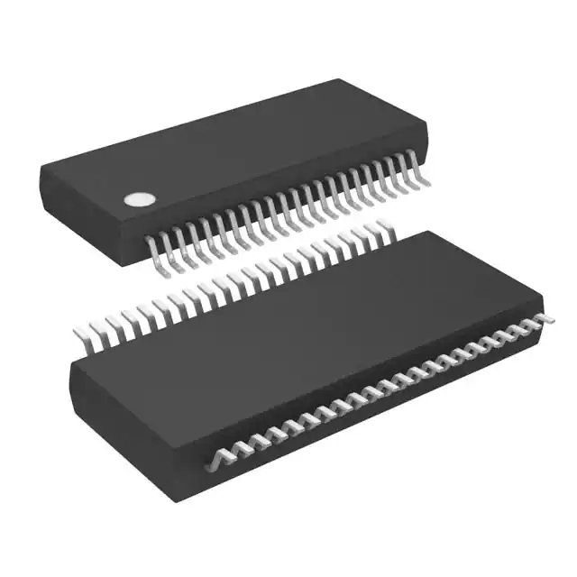
- Part No.:
- LTC6803IG-1#TRPBF
- Manufacturer:
- Analog Devices Inc.
- Category:
- Battery Management
- Package:
- 44-FSOP (0.209", 5.30mm Width)
- Datasheet:
-
 LTC6803IG-1#TRPBF.pdf
- Description:
- IC BATT MON MULTI 1-12C 44SSOP
- Quantity:
- Payment:

- Shipping:

Inventory:4,746
Please send an inquiry. Send us your inquiry, and we will respond immediately.
Product details
Overview
LTC6803IG-1#TRPBF from Analog Devices (formerly Linear Technology) is a 12-cell battery monitor IC with integrated 12-bit delta-sigma ADC, precision 3.065V reference, passive cell balancing MOSFETs, and daisy-chainable SPI-compatible serial interface. It supports up to 75V total stack voltage, achieves ±2.8mV total measurement error at 3.6V cell voltage, and operates from –40°C to 85°C in automotive and industrial battery management systems.
For engineers reviewing the LTC6803IG-1#TRPBF datasheet, LTC6803IG-1#TRPBF pinout, LTC6803IG-1#TRPBF application, or LTC6803IG-1#TRPBF equivalent, key selection criteria include its internal C0-to-V– connection for drop-in LTC6802‑1 replacement, 13ms full-stack measurement time, 12µA standby supply current, and ISO26262-compliant architecture for functional safety-critical BMS designs.
Technical Context
The LTC6803IG-1#TRPBF implements a high-voltage input multiplexer feeding a 12-bit delta-sigma ADC with built-in noise filtering and 8ppm/°C reference stability. Its level-shifting serial interface enables galvanically isolated daisy-chaining without optocouplers - CSBO/SCKO/SDOI outputs drive adjacent devices while CSBI/SCKI/SDI accept inputs from upstream units.
It features dual-mode digital I/O: voltage-mode (VMODE = VREG) for TTL-level host MCU interfacing, and current-mode (VMODE = V–) for inter-device communication. Cell balancing is implemented via 12 dedicated Sx pins with integrated 20Ω NMOS switches, controllable only by host processor writes to configuration registers - no autonomous decision logic is embedded.
Key Specifications
| Parameter | Value and Actual Design Meaning |
|---|---|
| Total Supply Voltage | Up to 75V (V+ to V–); enables direct monitoring of 12S Li-ion or 20S LFP stacks without external level shifters. |
| Cell Measurement Accuracy | ±2.8mV max total error at 3.6V (LTC6803IG grade); ensures <0.25% full-scale error for precise state-of-charge estimation. |
| Measurement Time | 13ms for all 12 cells; supports real-time BMS response in fast-changing load conditions. |
| Standby Supply Current | 12µA typical; minimizes parasitic drain in parked EVs or backup power systems. |
| Cell Balancing | Integrated 20Ω NMOS on each Sx pin; allows direct discharge control or external FET gate driving with pull-up PMOS. |
| Temperature Range | –40°C to +85°C (Industrial grade); validated for under-hood automotive and industrial UPS environments. |
| Package | 44-lead SSOP (G package); surface-mount compatible with standard reflow profiles and automated optical inspection. |
Pinout & Package
Package: 44-lead plastic SSOP (G package), 0.209" body width, JEDEC MS-013AC compliant. Thermal resistance θJA = 70°C/W.
| Pin/Terminal | Circuit Role | Design Meaning |
|---|---|---|
| CSBO (1) | Chip Select Output | Active-low buffered CSBI signal driving next device in daisy chain; eliminates need for external level shifters. |
| SDOI (2) | Serial Data I/O | Bi-directional data path between adjacent LTC6803 devices; enables isolated stack communication without optocouplers. |
| SCKO (3) | Serial Clock Output | Buffered SCKI output synchronizing downstream device; maintains timing integrity across multi-IC chains. |
| V+ (4) | Positive Supply Input | Accepts up to 75V; powers internal circuitry and enables zero-current shutdown when floated. |
| C12–C1 (5,7,9,11,13,15,17,19,21,23,25,27) | Cell Voltage Inputs | High-impedance inputs measuring 12 series-connected cells; C12 referenced to V+ and C0 to V– (LTC6803-1). |
| S12–S1 (6,8,10,12,14,16,18,20,22,24,26,28) | Cell Balancing Outputs | Open-drain NMOS with 20Ω RDS(on); directly discharges overcharged cells or drives external balancing FET gates. |
| V– (29) | Negative Supply Reference | Internally connected to C0 in LTC6803-1; establishes Kelvin reference for bottom cell measurement accuracy. |
| VTEMP1/VTEMP2 (31,32) | Thermistor Inputs | ADC-measured analog inputs (0–5.125V vs V–); support NTC/PTC sensing with onboard 3.065V reference. |
| VREF (33) | Precision Reference Output | 3.065V ±10mV, 8ppm/°C TC; supplies stable reference for external thermistor dividers and ADC calibration. |
| VMODE (40) | Interface Mode Select | Configures serial I/O as TTL (VMODE=VREG) or current-mode (VMODE=V–) for daisy-chain compatibility. |
Key Features
| Feature | Design Value |
|---|---|
| Stackable Daisy-Chain Architecture | Enables monitoring of >100 cells using only 4 host MCU pins - no isolators, optocouplers, or additional level-shifting ICs required. |
| Passive Cell Balancing with Integrated FETs | 12 dedicated Sx pins with 20Ω NMOS switches reduce PCB area and BOM count versus discrete balancing solutions. |
| ISO26262-Compliant Design | Built-in self-tests, watchdog timer with 1–2.5s timeout, and open-wire fault detection support ASIL-B functional safety requirements. |
| Low-Power Standby & Hardware Shutdown | 12µA standby current and <1nA hardware shutdown current extend battery life in always-on BMS applications. |
| Kelvin C0-to-V– Connection | Eliminates PCB trace IR drop error on bottom cell measurement - critical for accurate SOC estimation in high-current systems. |
Applications
| Electric Vehicle Battery Packs | Industrial Backup Power Systems |
|---|---|
Use Scenario: Monitoring 12S–96S lithium-ion battery modules in BEV traction packs with thermal runaway prevention. IC Role / Device Role / Timing Role: Primary cell voltage acquisition node in distributed BMS architecture; performs synchronized 13ms full-stack measurements every 100ms. Use Value: Enables precise per-cell SOC/SOH calculation and overvoltage protection within <±2.8mV error - meeting OEM requirements for pack longevity and warranty compliance. | Use Scenario: Supervising telecom or datacenter UPS battery strings where runtime predictability and maintenance scheduling are critical. IC Role / Device Role / Timing Role: Centralized voltage and temperature monitor in modular rack-mounted battery cabinets; interfaces via isolated SPI to system controller. Use Value: Reduces false low-battery alarms by eliminating common-mode noise errors through daisy-chain isolation and 75V stack tolerance. |
| Electric Bicycles & Scooters | High-Power Portable Medical Equipment |
Use Scenario: Compact BMS for 10S–13S LiCoO₂ packs in e-bikes with integrated cell balancing and thermal monitoring. IC Role / Device Role / Timing Role: Single-chip solution handling cell voltage, die temperature, and two external NTC sensors - all in 44-pin SSOP footprint. Use Value: Achieves <13ms measurement cycle and 12µA standby current, extending ride range by minimizing quiescent drain during storage. | Use Scenario: Battery health monitoring in portable defibrillators and infusion pumps requiring medical-grade reliability and low-power operation. IC Role / Device Role / Timing Role: Safety-critical voltage supervisor with watchdog timer and open-wire detection - triggers fail-safe shutdown on communication loss or sensor fault. Use Value: Meets IEC 60601-1 leakage current limits via hardware shutdown mode (<1nA) and built-in self-test sequences. |
Equivalent & Alternatives
The following parts are listed as comparable options for similar battery monitoring applications.
| Alternative Part | Technical Difference | Application Difference | Selection Advice |
|---|---|---|---|
| LTC6811IG-1#TRPBF | 3rd-generation 12-channel monitor with improved ±1.5mV measurement error, 2x faster conversion (6.5ms), and enhanced EMI immunity. | Required for new designs targeting ASIL-C or needing tighter voltage tolerance in high-precision LiFePO₄ applications. | Select when upgrading legacy LTC6803-based systems for higher accuracy or faster sampling - not pin-compatible; requires PCB redesign. |
| MAX17853GCM+ | Analog Devices' MAXIM-branded 14-channel monitor with integrated hot-swap controller, 1.25mV error, and AEC-Q100 Grade 1 qualification. | Preferred for automotive OEM programs requiring full AEC-Q100 certification and CAN FD communication interface. | Choose for new automotive platforms demanding certified components and integrated protection features - different pinout and protocol stack. |
Compared with LTC6803IG-1#TRPBF, LTC6811IG-1#TRPBF delivers higher accuracy and speed but requires layout changes, while MAX17853GCM+ adds automotive qualification and CAN FD at the cost of increased complexity and non-drop-in replacement.
Availability
LTC6803IG-1#TRPBF is available at Aetrix Electronics and suitable for electric vehicle battery packs, industrial backup power systems, and high-power portable medical equipment requiring stable component supply across extended production lifecycles.
Supply support for LTC6803IG-1#TRPBF includes scheduled delivery planning, volume procurement assistance, BOM continuity management, traceable sourcing, and lifecycle availability coordination for OEM customers, industrial embedded developers, connected-device designers, and electronics production programs.
Manufacturer
Analog Devices, Inc. (ADI) is a global semiconductor leader specializing in high-performance analog, mixed-signal, and digital signal processing technologies for industrial, automotive, communications, and healthcare markets.
The LTC6803 product line was engineered specifically for high-reliability battery management in electric transportation and energy storage - emphasizing stack scalability, functional safety, and low-power operation in harsh environments.
FAQ
What is the maximum number of cells that LTC6803IG-1#TRPBF can monitor in a single device?
LTC6803IG-1#TRPBF monitors up to 12 series-connected battery cells or supercapacitors per IC. Multiple LTC6803IG-1#TRPBF devices can be daisy-chained to monitor longer stacks - for example, eight devices monitor 96 cells. The architecture uses level-shifted serial communication, eliminating optocouplers or isolators in multi-IC configurations.
Does LTC6803IG-1#TRPBF support passive cell balancing, and how is it implemented?
Yes, LTC6803IG-1#TRPBF supports passive cell balancing via 12 dedicated Sx pins (S1–S12), each integrating a 20Ω NMOS switch. These switches are controlled exclusively by host processor commands - no autonomous balancing logic exists. The IC also provides pull-up PMOS on Sx pins to drive external high-power balancing FETs when higher discharge current is needed.
What is the purpose of the VMODE pin on LTC6803IG-1#TRPBF, and how should it be configured?
The VMODE pin configures the serial interface mode: tie VMODE to VREG for voltage-mode (TTL-level) operation with SDO, SDI, SCKI, and CSBI active - used when interfacing directly with a microcontroller. Tie VMODE to V– for current-mode operation, disabling SDO and enabling daisy-chain communication via SDOI/SCKO/CSBO - required for inter-device links in stacked architectures.
How does LTC6803IG-1#TRPBF achieve functional safety compliance for automotive applications?
LTC6803IG-1#TRPBF supports ISO26262-compliant system design through built-in self-tests, watchdog timer (1–2.5s timeout), open-wire fault detection on all cell inputs, and hardware shutdown mode (<1nA). While not ASIL-certified itself, its architecture enables ASIL-B decomposition in distributed BMS implementations when combined with appropriate system-level diagnostics and redundancy.
What is the difference between LTC6803IG-1#TRPBF and LTC6803IG-3#TRPBF?
LTC6803IG-1#TRPBF internally connects C0 to V–, enabling direct replacement of LTC6802‑1 with identical pinout and wiring. LTC6803IG-3#TRPBF separates C0 and V–, providing Kelvin sensing for improved C1 measurement accuracy and enhanced noise immunity - requiring modified PCB layout and cabling but delivering superior bottom-cell voltage fidelity in high-noise environments.
LTC6803IG-1#TRPBF Specifications
- Product attributes
- Attribute value
- Manufacturer:
- Analog Devices Inc.
- Series:
- -
- Package/Case:
- 44-FSOP (0.209", 5.30mm Width)
- Packaging:
- Tape & Reel (TR)
- Product Status:
- Active
- Function:
- Battery Monitor
- Battery Chemistry:
- Multi-Chemistry
- Number of Cells:
- 1 ~ 12
- Fault Protection:
- Over/Under Voltage
- Interface:
- Serial
- Operating Temperature:
- -40°C ~ 85°C (TA)
- Grade:
- -
- Qualification:
- -
- Mounting Type:
- Surface Mount
- Supplier Device Package:
- 44-SSOP
LTC6803IG-1#TRPBF FAQ
1.How can I place an order for LTC6803IG-1#TRPBF through Aetrix?
Please submit a Request for Quotation (RFQ) for LTC6803IG-1#TRPBF on Aetrix. Our sales agent will provide a competitive quotation and guide you through the order confirmation once you accept the terms.
2.Are the price and stock information for LTC6803IG-1#TRPBF reliable?
The price and inventory of LTC6803IG-1#TRPBF are updated periodically and may fluctuate due to market conditions. Stock and pricing data are typically refreshed every 24 hours. Quotation validity for LTC6803IG-1#TRPBF is usually 5 days.
3.What payment methods are accepted for LTC6803IG-1#TRPBF?
We accept Wire Transfer, PayPal, Credit Card, Western Union, MoneyGram, and Escrow for LTC6803IG-1#TRPBF transactions.
Note: Certain payment methods may incur a processing fee.
4.How is shipping managed for LTC6803IG-1#TRPBF?
LTC6803IG-1#TRPBF orders can be shipped via leading logistics carriers, including DHL, UPS, FedEx, TNT, or Registered Mail.
Once your LTC6803IG-1#TRPBF order is processed, you will receive an email with the shipment details and tracking number.
Note: Tracking information may take up to 24 hours to appear. Express delivery typically takes 3–5 business days.
5.How can I obtain technical support or documentation for LTC6803IG-1#TRPBF?
For technical support, including LTC6803IG-1#TRPBF datasheets, pinout diagrams, or application guidance, please contact our engineering support team. They can provide detailed documentation and assistance for your LTC6803IG-1#TRPBF requirements.
6.How does Aetrix verify that LTC6803IG-1#TRPBF is sourced from the original manufacturer or authorized distributors?
All LTC6803IG-1#TRPBF products on Aetrix are procured from qualified distributors and authorized channels. Our dedicated quality assurance team conducts strict verification, including traceability checks and, if necessary, third-party testing. This ensures that LTC6803IG-1#TRPBF meets industry standards.
7.What is the process for return or replacement of LTC6803IG-1#TRPBF?
All LTC6803IG-1#TRPBF units undergo pre-shipment inspection (PSI). If there is an issue with LTC6803IG-1#TRPBF, returns or replacements are accepted under the following conditions:
1.Quantity discrepancies, incorrect items, or visible external defects (such as breakage or corrosion), acknowledged by Aetrix.
2.The issue is reported within 90 days of delivery.
3.The LTC6803IG-1#TRPBF part is unused and in its original packaging.
Return procedure for LTC6803IG-1#TRPBF:
1.Submit a request within 90 days.
2.Obtain a Return Material Authorization (RMA) from Aetrix.
LTC6803IG-1#TRPBF Tags

-
BQ29700DSER
Texas Instruments

-
S-8241ABKMC-GBKT2G
ABLIC Inc.
-
S-8241ABPMC-GBPT2G
ABLIC Inc.

-
BQ27427YZFR
Texas Instruments

-
BQ27426YZFR
Texas Instruments

-
STC3117IJT
STMicroelectronics

-
STC3115IJT
STMicroelectronics

-
BQ76925RGER
Texas Instruments
-
NPM1100-QDAA-R
Nordic Semiconductor ASA

-
BQ27441DRZR-G1A
Texas Instruments

-
STC3115AIQT
STMicroelectronics

-
S-8252AAL-M6T1U
ABLIC Inc.
Tech Hub

A practical engineering guide to 3.3V and 5V logic compatibility, input thresholds, resistor dividers, translator ICs, MOSFET level shifting, I2C pull-ups, timing limits and power-sequencing risks.

The 74HC595 uses push-pull logic outputs, while the TPIC6B595 uses 50 V open-drain DMOS sinks for higher-power loads. This guide compares timing, current limits, 3.3 V interfacing, load wiring, thermal…

The 74HC595 converts serial data into eight stable parallel outputs. This guide covers pin functions, shift and storage timing, OE and MR behavior, drive-current limits, cascading, voltage compatibilit…

A technical comparison of level-sensitive latches and edge-triggered flip-flops, covering timing windows, setup and hold limits, master–slave operation, time borrowing, race-through, HDL inference and…

A D latch stores one bit while Enable controls when data can pass. This reference covers gate-level operation, truth tables, transparency, setup and hold timing, LE versus OE, common ICs and practical …

An SR latch stores one bit through cross-coupled feedback. This engineering reference covers NOR and NAND implementations, truth tables, forbidden-state recovery, gated operation, switch debouncing, fa…

Latch circuits retain one bit through feedback. This technical reference covers SR and D latches, truth tables, transparency, timing limits, latch-versus-flip-flop behavior, applications and common log…

An engineering guide to LED driver operation, constant-current and constant-voltage outputs, linear and switching topologies, dimming, IC selection, calculations, replacement compatibility, and fault c…

Operational amplifier guide covering op amp basics, feedback, ideal vs real op amps, common configurations, buffer circuits, offset, bias current, gain-bandwidth, slew rate, rail-to-rail limits and sel…

Jumper cables guide covering safe connection order, red and black clamp placement, final ground connection, cable gauge, length, clamp quality, copper vs CCA cables, jump starter comparison and battery…


