
 My Inquiry
 My Account


Analog Devices Inc. LTC6806ILW#3ZZPBF
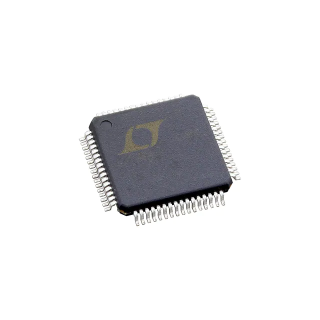
- Part No.:
- LTC6806ILW#3ZZPBF
- Manufacturer:
- Analog Devices Inc.
- Category:
- Battery Management
- Package:
- 64-LQFP
- Datasheet:
-
 LTC6806ILW#3ZZPBF.pdf
- Description:
- IC BATT MON MULT-CHEM 36C 64LQFP
- Quantity:
- Payment:

- Shipping:

Inventory:3,662
Please send an inquiry. Send us your inquiry, and we will respond immediately.
Product details
Overview
LTC6806ILW#3ZZPBF from Analog Devices is a 36-channel fuel cell monitor IC designed for high-accuracy voltage measurement across series-connected fuel cells in automotive and industrial energy systems. It measures up to 144 fuel cells with ±5V per channel, achieves ≤15mV total measurement error, and operates from a single 5V supply. Its primary role is cell-level monitoring in large fuel cell stacks for electric/hybrid vehicles and backup power systems.
For engineers reviewing the LTC6806ILW#3ZZPBF datasheet, LTC6806ILW#3ZZPBF pinout, LTC6806ILW#3ZZPBF application, or LTC6806ILW#3ZZPBF equivalent, key selection criteria include isoSPI daisy-chain capability, AEC-Q100 qualification, 6.75ms full-system measurement time in fast ADC mode, and support for –80V to +150V stack voltages with channel-specific common-mode ranges.
Technical Context
The LTC6806ILW#3ZZPBF implements a delta-sigma ADC architecture with programmable input range (±2.5V or ±5V via HIRNG), integrated noise filtering, and selectable acquisition modes (Normal, Fast, Filtered, Alternate). It supports three distinct cell voltage input ranges: C0–C13 (–5V to +60V), C14–C24 (–5V to +95V), and C25–C36 (–5V to +140V) relative to V–, enabling direct connection to large fuel cell stacks without external level-shifting.
Its dual-isoSPI interface enables bidirectional, RF-immune communication at 1MB/s over twisted-pair cables up to 100 meters. Two hardware-selectable modes-daisy-chain (single host connection) and parallel (individual addressing)-allow flexible scalability from small to multi-hundred-cell systems, with up to 12 devices cascaded for 432-cell monitoring.
Key Specifications
| Parameter | Value and Actual Design Meaning |
|---|---|
| Measurement Channels | 36 independent inputs, each configurable to monitor 1–4 series fuel cells (up to 144 total per IC) |
| Total Measurement Error | ≤±15 mV in Normal mode (HIRNG = 0, 72V stack), enabling precise state-of-charge estimation |
| Cell Voltage Range | ±5 V per channel (HIRNG = 1), supporting 3.0–5.0 V/cell fuel cells with headroom for transients |
| Full-System Acquisition Time | 6.75 ms in Fast ADC mode, critical for real-time thermal and safety management loops |
| Stack Voltage Support | –80 V to +150 V (C25–C36 to V–), covering full operational range of high-power PEM fuel stacks |
| Supply & Power | Single 4.75–5.5 V supply; 12 µA sleep current enables low-power battery-backed monitoring |
| Interface | Built-in isoSPI™: 1 MB/s, bidirectional, isolated, daisy-chain or parallel topology, no optocouplers required |
| Qualification | AEC-Q100 Grade I (–40°C to +85°C junction), certified for automotive fuel cell control units |
Pinout & Package
Package: 64-lead LQFP (10 mm × 10 mm), RoHS-compliant, MSL Level 3, θJA = 34°C/W.
| Pin/Terminal | Circuit Role | Design Meaning |
|---|---|---|
| C0–C36 | Fuel cell voltage inputs | 37 differential sense points (C0 to C36); each pair (Cn, Cn−1) measures voltage across one or more cells; grouped into three voltage domains |
| V+, V– | Power supply rails | V+ = 4.75–5.5 V main supply; V– serves as system ground reference and bias for all analog inputs |
| ISOMD, DCMD | isoSPI mode configuration | Hardware-selectable pins: ISOMD sets daisy-chain vs parallel; DCMD selects SPI vs isoSPI physical layer |
| SDO_IBIAS, SDI_ICMP, SCK_IPA, CSB_IMA | Serial interface signals | Standard SPI pins repurposed for isoSPI; compatible with standard MCU SPI peripherals when DCMD = 0 |
| GPIO1–GPIO6 | General-purpose I/O | Configurable as digital inputs/outputs or analog sensor inputs (e.g., thermistors), with ±15 mV TME in Normal mode |
| VREF1, VREF2 | Internal voltage references | VREF1 (2.7–3.3 V, 10 ppm/°C TC) and VREF2 (2.2–2.7 V, 40 ppm/°C TC) enable ratiometric ADC calibration and sensor interfacing |
Key Features
| Feature | Design Value |
|---|---|
| Stackable isoSPI architecture | Enables monitoring of 432+ fuel cells using 12 daisy-chained LTC6806ICs with single host processor connection |
| Programmable input range (HIRNG) | Selects ±2.5 V (low-noise) or ±5 V (wide-range) per channel to match fuel cell voltage distribution and optimize SNR |
| Multi-domain cell input voltage rating | C0–C13: –5V to +60V; C14–C24: –5V to +95V; C25–C36: –5V to +140V - eliminates need for external level shifters in high-stack designs |
| Low-power sleep mode | 12 µA supply current with wake-on-isoSPI activity, enabling always-on fault detection without draining auxiliary batteries |
| Open-wire detection | Integrated pull-up/pull-down currents on all Cx pins (up to 100 µA at C13/C24) for automated interconnect integrity verification |
| AEC-Q100 automotive qualification | Validated for –40°C to +85°C operation (LTC6806I grade), including ESD (HBM Class 3A, CDM Class C4A) and thermal cycling reliability |
Applications
| Fuel Cell Electric Vehicle (FCEV) Powertrain | Industrial Backup Power System |
|---|---|
Use Scenario: Real-time monitoring of 200+ PEM fuel cells in a heavy-duty truck propulsion stack under dynamic load and temperature gradients. IC Role / Device Role / Timing Role: Primary cell voltage monitor; performs synchronized 36-channel measurements every 10.3 ms in Normal mode for SOC/SOH estimation and thermal runaway prevention. Use Value: ≤±15 mV TME ensures <0.5% voltage error at 3.3 V/cell, directly improving fuel efficiency modeling and predictive maintenance accuracy. |
Use Scenario: Continuous supervision of a 144-cell phosphoric acid fuel cell array in a telecom central office backup system operating 24/7. IC Role / Device Role / Timing Role: Stack supervisor IC; uses daisy-chained isoSPI to aggregate data from six LTC6806ICs, reporting to PLC over RS-485 gateway. Use Value: 1 MB/s isoSPI immunity to EMI from nearby rectifiers and inverters eliminates communication errors in electrically noisy environments. |
| High-Power Portable Fuel Cell Generator | Hybrid Fuel Cell–Battery Energy Storage |
Use Scenario: Compact 48-cell portable generator for field-deployable military applications requiring ruggedized, low-power monitoring. IC Role / Device Role / Timing Role: Standalone fuel cell manager; leverages GPIOs for thermistor-based temperature sensing and VREF2 for ratiometric ADC calibration. Use Value: 12 µA sleep current extends auxiliary battery life to >6 months between charges during standby, reducing maintenance frequency. |
Use Scenario: Coordinated voltage balancing between 72 fuel cells and Li-ion buffer bank in a microgrid islanding system. IC Role / Device Role / Timing Role: High-precision cell monitor feeding data to battery management controller; uses filtered ADC mode to reject switching noise from DC–DC converters. Use Value: Delta-sigma filtering and 60 dB CMRR at 100 kHz suppresses 200 kHz converter ripple, preventing false overvoltage trips. |
Equivalent & Alternatives
The following parts are listed as comparable options for similar fuel cell monitoring applications.
| Alternative Part | Technical Difference | Application Difference | Selection Advice |
|---|---|---|---|
| LTC6813-1#3ZZPBF | 18-channel version; same isoSPI, AEC-Q100, and TME specs; requires two ICs for 36-channel coverage | Lower channel count suits smaller stacks (<90 cells); reduced PCB area but higher component count for large systems | Choose for cost-sensitive, space-constrained designs where stack size permits channel splitting |
| ADuM6420AARWZ | Isolated SPI digital isolator only - no ADC, no fuel cell sensing, no voltage references | Must be paired with external ADC and signal conditioning; adds complexity, BOM cost, and calibration burden | Consider only if existing design uses discrete ADC and requires only isolation upgrade, not full monitoring solution |
Compared with LTC6806ILW#3ZZPBF, LTC6813-1#3ZZPBF offers identical precision and automotive qualification but halves channel density, increasing system-level component count; ADuM6420AARWZ provides only isolation functionality and cannot replace the integrated measurement, reference, and diagnostics capabilities of the LTC6806ILW#3ZZPBF.
Availability
LTC6806ILW#3ZZPBF is available at Aetrix Electronics and suitable for fuel cell electric vehicles, backup power systems, and high-power portable equipment requiring stable component supply, AEC-Q100 compliance, and long-term lifecycle support.
Supply support for LTC6806ILW#3ZZPBF includes scheduled delivery planning, volume procurement assistance, BOM continuity management, traceable sourcing, and lifecycle availability coordination for OEM customers, industrial embedded developers, connected-device designers, and electronics production programs.
Manufacturer
Analog Devices, Inc. is a global leader in high-performance analog, mixed-signal, and digital signal processing semiconductors, serving industrial, automotive, communications, and healthcare markets.
The LTC6806ILW#3ZZPBF belongs to Analog Devices' high-accuracy battery and fuel cell monitor product line, engineered specifically for safe, reliable, and precise voltage monitoring in high-voltage electrochemical energy storage and generation systems.
FAQ
What is the maximum number of fuel cells that a single LTC6806ILW#3ZZPBF can monitor?
A single LTC6806ILW#3ZZPBF monitors up to 144 fuel cells by measuring 36 differential inputs, each configurable to cover 1–4 series-connected cells. The device's ±5V input range per channel accommodates typical fuel cell voltages (3.0–5.0 V) with margin for transient events. This capacity is achieved without external multiplexing or level-shifting circuitry.
Does LTC6806ILW#3ZZPBF support daisy-chaining, and how many devices can be connected?
Yes, LTC6806ILW#3ZZPBF supports daisy-chaining via its isoSPI interface. Up to 12 devices can be connected in series, enabling simultaneous monitoring of 432 fuel cells using a single host processor connection. Each device forwards commands and data downstream, maintaining deterministic timing and eliminating address conflicts inherent in parallel bus architectures.
What is the total measurement error specification for LTC6806ILW#3ZZPBF, and under what conditions is it guaranteed?
The LTC6806ILW#3ZZPBF guarantees ≤±15 mV total measurement error (TME) in Normal ADC mode with HIRNG = 0, measured across C(n) to C(n−1) at 0 V or ±1.25 V input, VCx > 0 V, and 72 V stack voltage. This specification applies over the full –40°C to +85°C junction temperature range and 4.75–5.5 V supply, ensuring consistent accuracy in automotive and industrial environments.
How does the LTC6806ILW#3ZZPBF handle different common-mode voltage ranges across its 36 channels?
The LTC6806ILW#3ZZPBF partitions its 36 cell inputs into three groups with distinct absolute voltage ratings relative to V–: C0–C13 (–5 V to +60 V), C14–C24 (–5 V to +95 V), and C25–C36 (–5 V to +140 V). This architecture allows direct connection to high-voltage fuel cell stacks without external level shifters, as each group maps to physically adjacent cells in the stack where common-mode voltage increases linearly.
Is LTC6806ILW#3ZZPBF qualified for automotive use, and what does the #3ZZ suffix indicate?
Yes, LTC6806ILW#3ZZPBF is AEC-Q100 qualified for automotive applications (Grade I, –40°C to +85°C junction). The #3ZZ suffix denotes controlled manufacturing, enhanced traceability, and automotive-specific reliability testing-including extended temperature cycling, HTOL, and ESD validation-required for deployment in fuel cell electric vehicle powertrain control units.
LTC6806ILW#3ZZPBF Specifications
- Product attributes
- Attribute value
- Manufacturer:
- Analog Devices Inc.
- Series:
- -
- Package/Case:
- 64-LQFP
- Packaging:
- Tray
- Product Status:
- Active
- Function:
- Battery Monitor
- Battery Chemistry:
- Multi-Chemistry
- Number of Cells:
- 36
- Fault Protection:
- Over/Under Voltage
- Interface:
- Serial
- Operating Temperature:
- -40°C ~ 85°C (TJ)
- Grade:
- Automotive
- Qualification:
- -
- Mounting Type:
- Surface Mount
- Supplier Device Package:
- 64-LQFP (10x10)
LTC6806ILW#3ZZPBF FAQ
1.How can I place an order for LTC6806ILW#3ZZPBF through Aetrix?
Please submit a Request for Quotation (RFQ) for LTC6806ILW#3ZZPBF on Aetrix. Our sales agent will provide a competitive quotation and guide you through the order confirmation once you accept the terms.
2.Are the price and stock information for LTC6806ILW#3ZZPBF reliable?
The price and inventory of LTC6806ILW#3ZZPBF are updated periodically and may fluctuate due to market conditions. Stock and pricing data are typically refreshed every 24 hours. Quotation validity for LTC6806ILW#3ZZPBF is usually 5 days.
3.What payment methods are accepted for LTC6806ILW#3ZZPBF?
We accept Wire Transfer, PayPal, Credit Card, Western Union, MoneyGram, and Escrow for LTC6806ILW#3ZZPBF transactions.
Note: Certain payment methods may incur a processing fee.
4.How is shipping managed for LTC6806ILW#3ZZPBF?
LTC6806ILW#3ZZPBF orders can be shipped via leading logistics carriers, including DHL, UPS, FedEx, TNT, or Registered Mail.
Once your LTC6806ILW#3ZZPBF order is processed, you will receive an email with the shipment details and tracking number.
Note: Tracking information may take up to 24 hours to appear. Express delivery typically takes 3–5 business days.
5.How can I obtain technical support or documentation for LTC6806ILW#3ZZPBF?
For technical support, including LTC6806ILW#3ZZPBF datasheets, pinout diagrams, or application guidance, please contact our engineering support team. They can provide detailed documentation and assistance for your LTC6806ILW#3ZZPBF requirements.
6.How does Aetrix verify that LTC6806ILW#3ZZPBF is sourced from the original manufacturer or authorized distributors?
All LTC6806ILW#3ZZPBF products on Aetrix are procured from qualified distributors and authorized channels. Our dedicated quality assurance team conducts strict verification, including traceability checks and, if necessary, third-party testing. This ensures that LTC6806ILW#3ZZPBF meets industry standards.
7.What is the process for return or replacement of LTC6806ILW#3ZZPBF?
All LTC6806ILW#3ZZPBF units undergo pre-shipment inspection (PSI). If there is an issue with LTC6806ILW#3ZZPBF, returns or replacements are accepted under the following conditions:
1.Quantity discrepancies, incorrect items, or visible external defects (such as breakage or corrosion), acknowledged by Aetrix.
2.The issue is reported within 90 days of delivery.
3.The LTC6806ILW#3ZZPBF part is unused and in its original packaging.
Return procedure for LTC6806ILW#3ZZPBF:
1.Submit a request within 90 days.
2.Obtain a Return Material Authorization (RMA) from Aetrix.
LTC6806ILW#3ZZPBF Tags

-
BQ29700DSER
Texas Instruments

-
S-8241ABKMC-GBKT2G
ABLIC Inc.
-
S-8241ABPMC-GBPT2G
ABLIC Inc.

-
BQ27427YZFR
Texas Instruments

-
BQ27426YZFR
Texas Instruments

-
STC3117IJT
STMicroelectronics

-
STC3115IJT
STMicroelectronics

-
BQ76925RGER
Texas Instruments
-
NPM1100-QDAA-R
Nordic Semiconductor ASA

-
BQ27441DRZR-G1A
Texas Instruments

-
STC3115AIQT
STMicroelectronics

-
S-8252AAL-M6T1U
ABLIC Inc.
Tech Hub

A practical engineering guide to 3.3V and 5V logic compatibility, input thresholds, resistor dividers, translator ICs, MOSFET level shifting, I2C pull-ups, timing limits and power-sequencing risks.

The 74HC595 uses push-pull logic outputs, while the TPIC6B595 uses 50 V open-drain DMOS sinks for higher-power loads. This guide compares timing, current limits, 3.3 V interfacing, load wiring, thermal…

The 74HC595 converts serial data into eight stable parallel outputs. This guide covers pin functions, shift and storage timing, OE and MR behavior, drive-current limits, cascading, voltage compatibilit…

A technical comparison of level-sensitive latches and edge-triggered flip-flops, covering timing windows, setup and hold limits, master–slave operation, time borrowing, race-through, HDL inference and…

A D latch stores one bit while Enable controls when data can pass. This reference covers gate-level operation, truth tables, transparency, setup and hold timing, LE versus OE, common ICs and practical …

An SR latch stores one bit through cross-coupled feedback. This engineering reference covers NOR and NAND implementations, truth tables, forbidden-state recovery, gated operation, switch debouncing, fa…

Latch circuits retain one bit through feedback. This technical reference covers SR and D latches, truth tables, transparency, timing limits, latch-versus-flip-flop behavior, applications and common log…

An engineering guide to LED driver operation, constant-current and constant-voltage outputs, linear and switching topologies, dimming, IC selection, calculations, replacement compatibility, and fault c…

Operational amplifier guide covering op amp basics, feedback, ideal vs real op amps, common configurations, buffer circuits, offset, bias current, gain-bandwidth, slew rate, rail-to-rail limits and sel…

Jumper cables guide covering safe connection order, red and black clamp placement, final ground connection, cable gauge, length, clamp quality, copper vs CCA cables, jump starter comparison and battery…


