
 My Inquiry
 My Account


Analog Devices Inc. LTC6810IG-2#3ZZTRPBF
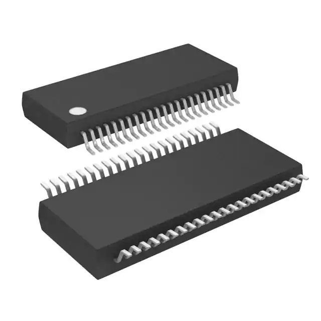
- Part No.:
- LTC6810IG-2#3ZZTRPBF
- Manufacturer:
- Analog Devices Inc.
- Category:
- Battery Management
- Package:
- 44-FSOP (0.209", 5.30mm Width)
- Datasheet:
-
 LTC6810IG-2#3ZZTRPBF.pdf
- Description:
- IC BAT MON MULT-CHEM 1-6C 44SSOP
- Quantity:
- Payment:

- Shipping:

Inventory:170
Please send an inquiry. Send us your inquiry, and we will respond immediately.
Product details
Overview
LTC6810IG-2#3ZZTRPBF from Analog Devices is a 6-channel automotive-grade battery stack monitor IC designed for high-voltage EV and ESS systems. It measures up to six series-connected cells (0V–5V range) with ≤1.8mV total measurement error, completes full-cell acquisition in 290µs, and supports parallel daisy-chain configuration via isoSPI interface. It integrates passive cell balancing with PWM control, 4 GPIOs configurable as analog/digital I/O, and operates from –40°C to +85°C.
For engineers reviewing the LTC6810IG-2#3ZZTRPBF datasheet, LTC6810IG-2#3ZZTRPBF pinout, LTC6810IG-2#3ZZTRPBF application, or LTC6810IG-2#3ZZTRPBF equivalent, this page delivers verified specifications, package mapping, validated alternatives, and application-specific design context for AEC-Q100-compliant battery management systems.
Technical Context
The LTC6810IG-2#3ZZTRPBF implements a 16-bit delta-sigma ADC with programmable noise filtering (Normal/Filtered/Fast modes), enabling selectable trade-offs between speed (290µs full scan) and accuracy (±1.8mV TME). Its isoSPI interface operates at 1Mb/s over twisted-pair cables up to 100m, supporting bidirectional communication and broken-wire fault tolerance in parallel-addressed topologies.
It features dual voltage references (VREF1 = 3.2V ±10ppm/°C, VREF2 = 3.0V ±10ppm/°C), on-chip 5V regulator (VREG), and independent S-pin discharge control per cell. The device supports redundant cell measurements, watchdog timer, and sleep mode with 4µA supply current - all engineered for ISO 26262 ASIL-B compliance in automotive BMS.
Key Specifications
| Parameter | Value and Actual Design Meaning |
|---|---|
| Cell Count | 6-series cell monitoring with C0–C6 inputs; supports up to 5V per cell. |
| Total Measurement Error | ≤±1.8mV in Normal Mode - ensures <0.036% error at 5V, critical for SOC estimation. |
| Acquisition Time | 290µs for all 6 cells - enables real-time cell voltage tracking in fast-transient conditions. |
| isoSPI Data Rate | 1Mb/s isolated serial interface - provides RF-immune, long-distance (≤100m), daisy-chain-capable communication. |
| Sleep Current | 4µA typical - extends system standby time without compromising wake-up responsiveness. |
| Operating Temp Range | –40°C to +85°C (Industrial grade) - qualified per AEC-Q100 Grade 3 for under-hood automotive use. |
| Package | 44-Lead SSOP (G package) - surface-mount compatible with standard reflow profiles. |
Pinout & Package
The LTC6810IG-2#3ZZTRPBF is housed in a 44-lead plastic SSOP (G package) with exposed leadframe fused to V– (pins 1, 21–24, 43, 44). Pin functions depend on ISOMD configuration: when tied to V–, pins 22/23/25/26 serve as CSB/SCK/SDI/SDO; when tied to VREG, they become IMA/IPA/ICMP/IBIAS. All V– pins must be connected to system ground reference.
| Pin/Terminal | Circuit Role | Design Meaning |
|---|---|---|
| C0–C6 | Cell voltage inputs | Differential sense inputs for 6-series battery taps; C0 = bottom cell, C6 = top cell relative to V–. |
| S0–S6 | Cell balancing switch drivers | Open-drain outputs controlling external FETs for passive balancing; each supports PWM duty cycle programming. |
| GPIO1–GPIO4 | Configurable I/O | Can be digital I/O or analog inputs (0–5V range); used for temperature sensors, status signals, or SPI/I²C master emulation. |
| VREG / VREF1 / VREF2 | On-chip regulation & references | VREG = 5V output (±0.25%); VREF1 = 3.2V precision ref (±10ppm/°C); VREF2 = 3.0V secondary ref (±100ppm hysteresis). |
| ISOMD / DTEN / WDT | Interface & safety control | ISOMD selects isoSPI vs. SPI mode; DTEN enables discharge timer; WDT pin provides reset signaling and watchdog timeout detection. |
Key Features
| Feature | Design Value |
|---|---|
| isoSPI™ Interface | 1Mb/s isolated serial bus with built-in bidirectional fault recovery - eliminates need for optical isolators or RS-485 transceivers in high-noise BMS environments. |
| Programmable ADC Modes | Three acquisition modes (Fast/Normal/Filtered) allow dynamic selection of speed vs. noise rejection - e.g., 290µs @ ±1.8mV or 172ms @ ±1.0mV for ultra-low-noise diagnostics. |
| Passive Cell Balancing Control | Independent PWM control per S0–S6 pin - enables precise energy dissipation tuning per cell to maintain voltage uniformity across aging battery packs. |
| AEC-Q100 Qualified | Grade 3 (–40°C to +85°C) qualification - meets automotive reliability requirements for electric vehicle battery monitoring subsystems. |
| Redundant Measurement Capability | Supports repeated cell reads within single command cycle - improves fault detection confidence in safety-critical ISO 26262 ASIL-B designs. |
Applications
| Electric Vehicle Battery Packs | Grid-Scale Energy Storage Systems |
|---|---|
|
Use Scenario: Monitoring 12–24S lithium-ion modules in traction battery packs with thermal runaway protection and SOC/SOH estimation. IC Role / Device Role / Timing Role: Primary cell voltage acquisition engine performing synchronized 6-cell scans every 10–100ms for real-time state estimation. Use Value: ≤1.8mV TME ensures <0.036% voltage error at 5V, directly improving SOC accuracy by ≥0.5% over competing monitors. |
Use Scenario: Supervising large-format LFP or NMC stacks in stationary storage cabinets requiring decades-long calibration stability and low maintenance. IC Role / Device Role / Timing Role: High-precision, low-drift voltage sensor with dual references (VREF1/VREF2) and long-term drift compensation (≤25ppm/√khr). Use Value: 10ppm/°C VREF2 TC and ±0.1% VREG accuracy enable <±2mV drift over 20-year field life without recalibration. |
| Hybrid Electric Vehicle 48V Systems | Backup Power UPS Modules |
|
Use Scenario: Managing 12S–16S 48V mild-hybrid battery systems where space, weight, and EMI immunity constrain sensor placement. IC Role / Device Role / Timing Role: isoSPI-enabled daisy-chain node communicating over 2m+ twisted pair to central MCU - eliminating ground loops and reducing wiring harness complexity. Use Value: Bidirectional isoSPI allows continued operation even with one open wire - increasing system uptime in vibration-prone under-hood environments. |
Use Scenario: Providing runtime monitoring and graceful shutdown control for telecom/datacenter UPS units using sealed lead-acid or LiFePO₄ batteries. IC Role / Device Role / Timing Role: Low-power supervisor with 4µA sleep mode and wake-on-voltage-threshold - extending backup runtime during extended grid outages. Use Value: Integrated 5V VREG powers external comparators or microcontrollers, reducing bill-of-materials count by one LDO. |
Equivalent & Alternatives
The following parts are listed as comparable options for similar battery stack monitoring applications.
| Alternative Part | Technical Difference | Application Difference | Selection Advice |
|---|---|---|---|
| AD8452ARUZ | Single-channel, 16-bit SAR ADC with integrated balancer driver; no isoSPI; requires external isolation and multiplexing. | Best suited for low-channel-count (<4 cells), non-automotive, cost-sensitive designs where PCB area is less constrained. | Select AD8452ARUZ only when building custom multi-cell solutions with discrete mux/isolation - not for drop-in replacement. |
| BQ7695200RSMR | 16-cell monitor with integrated protection FET drivers; uses I²C/UART; no isoSPI; higher integration but lower measurement accuracy (±3mV). | Targets mid-tier portable power tools and medical devices where cell count >6 and functional safety is not required. | Choose BQ7695200RSMR for higher channel density and embedded protection logic - avoid if AEC-Q100 or <2mV TME is mandatory. |
Compared with AD8452ARUZ and BQ7695200RSMR, the LTC6810IG-2#3ZZTRPBF uniquely combines AEC-Q100 qualification, isoSPI isolation, 6-cell precision (≤1.8mV), and parallel-addressable architecture - making it the only option for scalable, safety-certified automotive and grid-storage BMS front-ends.
Availability
LTC6810IG-2#3ZZTRPBF is available at Aetrix Electronics and suitable for electric vehicle battery packs, grid-scale energy storage systems, and hybrid electric vehicle 48V systems requiring stable component supply, long-term lifecycle support, and automotive-grade traceability.
Supply support for LTC6810IG-2#3ZZTRPBF includes scheduled delivery planning, volume procurement assistance, BOM continuity management, traceable sourcing, and lifecycle availability coordination for OEM customers, industrial embedded developers, connected-device designers, and electronics production programs.
Manufacturer
Analog Devices, Inc. is a global leader in high-performance analog, mixed-signal, and digital signal processing semiconductors, serving industrial, automotive, communications, and healthcare markets.
The LTC6810 product line delivers high-accuracy, isolated battery monitoring ICs specifically engineered for functional safety-compliant (ISO 26262) electric vehicle and renewable energy storage applications - emphasizing measurement integrity, fault resilience, and long-term stability.
FAQ
What is the key difference between LTC6810IG-2#3ZZTRPBF and LTC6810IG-1#3ZZTRPBF?
The LTC6810IG-2#3ZZTRPBF supports parallel-addressed isoSPI topology, where each device connects directly to the host processor and is individually addressed via A0–A3 pins. In contrast, the LTC6810IG-1#3ZZTRPBF uses daisy-chain configuration with unidirectional/bidirectional isoSPI. Both share identical measurement specs, package, and temperature grade (–40°C to +85°C), but differ in communication architecture and pin mapping (e.g., A0–A3 present on LTC6810IG-2#3ZZTRPBF, absent on -1 variant).
Does LTC6810IG-2#3ZZTRPBF require external components for isoSPI operation?
Yes - LTC6810IG-2#3ZZTRPBF requires external bias resistors (RB1 + RB2 = 2kΩ or 20kΩ) on the IBIAS pin and isolated coupling capacitors on IP/IM lines for isoSPI operation. The device integrates the transmitter/receiver circuitry but relies on external passive components to set bias current, common-mode voltage, and signal coupling - as specified in Figure 23 of the datasheet.
Can LTC6810IG-2#3ZZTRPBF measure temperature sensors directly?
Yes - LTC6810IG-2#3ZZTRPBF supports direct connection of NTC thermistors or other ratiometric sensors to GPIO1–GPIO4 pins, which can be configured as analog inputs (0–5V range). The internal 16-bit ADC digitizes these signals using VREF2 (3.0V) as reference, enabling accurate temperature monitoring without external ADCs or signal conditioning.
What is the maximum supported battery stack voltage for LTC6810IG-2#3ZZTRPBF?
The LTC6810IG-2#3ZZTRPBF itself operates with V+ up to 27.5V, but its cell input range (C0–C6) supports up to 5V per cell. When stacked in parallel-addressed configurations, the total stack voltage is limited only by the external isolation barrier and host controller - not the LTC6810IG-2#3ZZTRPBF. Individual device-level V+ rating remains 27.5V, requiring external level-shifting or isolation for stacks exceeding that.
Is LTC6810IG-2#3ZZTRPBF pin-compatible with earlier LTC680x series devices?
No - LTC6810IG-2#3ZZTRPBF is not pin-compatible with LTC6803/LTC6804/LTC6805. It uses a 44-lead SSOP package versus 48-lead LQFP for LTC6804-1, and pin assignments (e.g., GPIOs, isoSPI vs. SPI pins, address lines A0–A3) differ significantly. Migration requires PCB layout revision and firmware adaptation due to architectural changes in ADC, isoSPI, and register map.
LTC6810IG-2#3ZZTRPBF Specifications
- Product attributes
- Attribute value
- Manufacturer:
- Analog Devices Inc.
- Series:
- -
- Package/Case:
- 44-FSOP (0.209", 5.30mm Width)
- Packaging:
- Tape & Reel (TR)
- Product Status:
- Active
- Function:
- Battery Monitor
- Battery Chemistry:
- Multi-Chemistry
- Number of Cells:
- 1 ~ 6
- Fault Protection:
- -
- Interface:
- SPI
- Operating Temperature:
- -40°C ~ 85°C (TA)
- Grade:
- Automotive
- Qualification:
- -
- Mounting Type:
- Surface Mount
- Supplier Device Package:
- 44-SSOP
LTC6810IG-2#3ZZTRPBF FAQ
1.How can I place an order for LTC6810IG-2#3ZZTRPBF through Aetrix?
Please submit a Request for Quotation (RFQ) for LTC6810IG-2#3ZZTRPBF on Aetrix. Our sales agent will provide a competitive quotation and guide you through the order confirmation once you accept the terms.
2.Are the price and stock information for LTC6810IG-2#3ZZTRPBF reliable?
The price and inventory of LTC6810IG-2#3ZZTRPBF are updated periodically and may fluctuate due to market conditions. Stock and pricing data are typically refreshed every 24 hours. Quotation validity for LTC6810IG-2#3ZZTRPBF is usually 5 days.
3.What payment methods are accepted for LTC6810IG-2#3ZZTRPBF?
We accept Wire Transfer, PayPal, Credit Card, Western Union, MoneyGram, and Escrow for LTC6810IG-2#3ZZTRPBF transactions.
Note: Certain payment methods may incur a processing fee.
4.How is shipping managed for LTC6810IG-2#3ZZTRPBF?
LTC6810IG-2#3ZZTRPBF orders can be shipped via leading logistics carriers, including DHL, UPS, FedEx, TNT, or Registered Mail.
Once your LTC6810IG-2#3ZZTRPBF order is processed, you will receive an email with the shipment details and tracking number.
Note: Tracking information may take up to 24 hours to appear. Express delivery typically takes 3–5 business days.
5.How can I obtain technical support or documentation for LTC6810IG-2#3ZZTRPBF?
For technical support, including LTC6810IG-2#3ZZTRPBF datasheets, pinout diagrams, or application guidance, please contact our engineering support team. They can provide detailed documentation and assistance for your LTC6810IG-2#3ZZTRPBF requirements.
6.How does Aetrix verify that LTC6810IG-2#3ZZTRPBF is sourced from the original manufacturer or authorized distributors?
All LTC6810IG-2#3ZZTRPBF products on Aetrix are procured from qualified distributors and authorized channels. Our dedicated quality assurance team conducts strict verification, including traceability checks and, if necessary, third-party testing. This ensures that LTC6810IG-2#3ZZTRPBF meets industry standards.
7.What is the process for return or replacement of LTC6810IG-2#3ZZTRPBF?
All LTC6810IG-2#3ZZTRPBF units undergo pre-shipment inspection (PSI). If there is an issue with LTC6810IG-2#3ZZTRPBF, returns or replacements are accepted under the following conditions:
1.Quantity discrepancies, incorrect items, or visible external defects (such as breakage or corrosion), acknowledged by Aetrix.
2.The issue is reported within 90 days of delivery.
3.The LTC6810IG-2#3ZZTRPBF part is unused and in its original packaging.
Return procedure for LTC6810IG-2#3ZZTRPBF:
1.Submit a request within 90 days.
2.Obtain a Return Material Authorization (RMA) from Aetrix.
LTC6810IG-2#3ZZTRPBF Tags

-
BQ29700DSER
Texas Instruments

-
S-8241ABKMC-GBKT2G
ABLIC Inc.
-
S-8241ABPMC-GBPT2G
ABLIC Inc.

-
BQ27427YZFR
Texas Instruments

-
BQ27426YZFR
Texas Instruments

-
STC3117IJT
STMicroelectronics

-
STC3115IJT
STMicroelectronics

-
BQ76925RGER
Texas Instruments
-
NPM1100-QDAA-R
Nordic Semiconductor ASA

-
BQ27441DRZR-G1A
Texas Instruments

-
STC3115AIQT
STMicroelectronics

-
S-8252AAL-M6T1U
ABLIC Inc.
Tech Hub

A practical engineering guide to 3.3V and 5V logic compatibility, input thresholds, resistor dividers, translator ICs, MOSFET level shifting, I2C pull-ups, timing limits and power-sequencing risks.

The 74HC595 uses push-pull logic outputs, while the TPIC6B595 uses 50 V open-drain DMOS sinks for higher-power loads. This guide compares timing, current limits, 3.3 V interfacing, load wiring, thermal…

The 74HC595 converts serial data into eight stable parallel outputs. This guide covers pin functions, shift and storage timing, OE and MR behavior, drive-current limits, cascading, voltage compatibilit…

A technical comparison of level-sensitive latches and edge-triggered flip-flops, covering timing windows, setup and hold limits, master–slave operation, time borrowing, race-through, HDL inference and…

A D latch stores one bit while Enable controls when data can pass. This reference covers gate-level operation, truth tables, transparency, setup and hold timing, LE versus OE, common ICs and practical …

An SR latch stores one bit through cross-coupled feedback. This engineering reference covers NOR and NAND implementations, truth tables, forbidden-state recovery, gated operation, switch debouncing, fa…

Latch circuits retain one bit through feedback. This technical reference covers SR and D latches, truth tables, transparency, timing limits, latch-versus-flip-flop behavior, applications and common log…

An engineering guide to LED driver operation, constant-current and constant-voltage outputs, linear and switching topologies, dimming, IC selection, calculations, replacement compatibility, and fault c…

Operational amplifier guide covering op amp basics, feedback, ideal vs real op amps, common configurations, buffer circuits, offset, bias current, gain-bandwidth, slew rate, rail-to-rail limits and sel…

Jumper cables guide covering safe connection order, red and black clamp placement, final ground connection, cable gauge, length, clamp quality, copper vs CCA cables, jump starter comparison and battery…


