
 My Inquiry
 My Account


Analog Devices Inc. LTC6811IG-1#PBF
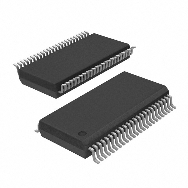
- Part No.:
- LTC6811IG-1#PBF
- Manufacturer:
- Analog Devices Inc.
- Category:
- Battery Management
- Package:
- 48-FSOP (0.209", 5.30mm Width)
- Datasheet:
-
 LTC6811IG-1#PBF.pdf
- Description:
- IC BATT MON MULTI 1-12C 48SSOP
- Quantity:
- Payment:

- Shipping:

Inventory:1,867
Please send an inquiry. Send us your inquiry, and we will respond immediately.
Product details
Overview
LTC6811IG-1#PBF from Analog Devices is a 12-cell battery stack monitor IC designed for high-voltage, safety-critical battery management systems. It achieves ≤1.2 mV total measurement error across 0 V to 5 V per cell, completes full 12-cell acquisition in 290 µs, and supports daisy-chained isoSPI communication up to 1 Mb/s over 100 m twisted pair - deployed in automotive EV traction battery packs and grid-scale energy storage.
For engineers reviewing the LTC6811IG-1#PBF datasheet, LTC6811IG-1#PBF pinout, LTC6811IG-1#PBF application, or LTC6811IG-1#PBF equivalent, key selection criteria include its AEC-Q100 qualification, ISO 26262-compatibility support, passive balancing with individual PWM control, 48-lead SSOP package, and dual ADC modes (Normal/Filtered/Fast) enabling trade-offs between speed (1010 µs), noise rejection (−70 dB at 100 Hz), and accuracy (±0.2 mV typical TME).
Technical Context
The LTC6811IG-1#PBF implements a 16-bit SAR ADC with programmable noise filtering, synchronized voltage/current sampling, and on-chip reference circuitry (VREF1 = 3.2 V ±10 mV, VREF2 = 3.0 V ±5 mV). Its isoSPI interface operates in daisy-chain topology (LTC6811-1 variant), using differential signaling with 1.6 V pulse amplitude and <35 ns receiver filter window for robust RF immunity.
Core operation includes three ADC acquisition modes: Fast (1010 µs for 12 cells, ±10 mV TME), Normal (2335 µs, ±1.2 mV TME), and Filtered (201 ms, ±0.1 mV TME). Cell balancing is implemented via 12 dedicated Sx pins driving external FETs, each controllable via independent 8-bit PWM duty cycle registers with programmable discharge timers.
Key Specifications
| Parameter | Value and Actual Design Meaning |
|---|---|
| Cell Count | 12-series cell monitoring with 0 V to 5 V input range per cell - supports Li-ion, LFP, and Ni-based chemistries without level-shifting. |
| Total Measurement Error | ≤±1.2 mV in Normal mode (25°C, C(n)–C(n–1)=3.3 V) - enables SOC estimation accuracy within ±0.5% for 3.3 V nominal cells. |
| Acquisition Time | 290 µs for all 12 cells in burst mode - allows sub-millisecond BMS state updates for fast transient response in EV regen braking. |
| isoSPI Data Rate | 1 Mb/s daisy-chain communication - supports >100 nodes in series with <300 ns cumulative daisy-chain delay per device. |
| Sleep Current | 4 µA supply current (VREG = 0 V) - extends standby life in backup battery systems with infrequent wake cycles. |
| Operating Temp | –40°C to +85°C (Industrial grade) - validated for under-hood BMS modules and industrial ESS enclosures without forced cooling. |
| Package | 48-lead plastic SSOP (G package), 0.5 mm pitch - compatible with standard reflow profiles and automated optical inspection. |
Pinout & Package
Package: 48-lead plastic SSOP (G package), 0.5 mm pitch, thermal resistance θJA = 55°C/W, max junction temperature 150°C.
| Pin/Terminal | Circuit Role | Design Meaning |
|---|---|---|
| V+ | High-side supply input | Accepts 11 V to 55 V stack voltage; powers internal analog circuitry and isolates digital domain via on-chip regulator. |
| C0–C12 | Cell voltage inputs | Differential inputs measuring voltage across each of 12 series-connected cells; C0 = bottom cell (to V–), C12 = top cell (to V+). |
| S1–S12 | Passive balance FET drivers | Open-drain outputs controlling external N-channel MOSFETs; each supports independent PWM duty cycle for precision thermal management. |
| ISOMD | Interface mode select | Tied to V– for LTC6811-1 daisy-chain SPI mode; tied to VREG for parallel-addressed LTC6811-2 configuration. |
| SDO/SDI/SCK/CSB | Standard SPI interface | Used only when ISOMD = V–; enables host MCU direct register access without isoSPI transceiver. |
| GPIO1–GPIO5 | Configurable I/O | Support analog sensing (temperature, voltage), digital I/O, or I²C/SPI master functions - expands system monitoring without extra ICs. |
| VREG | On-chip 5 V regulator output | Supplies internal digital logic and external peripherals; ±0.25% regulation accuracy ensures stable timing and ADC reference integrity. |
| VREF1/VREF2 | Precision voltage references | VREF1 = 3.2 V ±10 mV (3 ppm/°C TC); VREF2 = 3.0 V ±5 mV (10 ppm/°C TC) - used for ADC calibration and external sensor biasing. |
Key Features
| Feature | Design Value |
|---|---|
| isoSPI daisy-chain architecture | Enables scalable BMS designs up to 100+ cells with single host connection and deterministic latency (<1 µs per node). |
| Programmable ADC noise filtering | Three selectable modes (Fast/Normal/Filtered) let designers optimize for real-time control (EV torque response) or high-precision diagnostics (cell imbalance detection). |
| Individual cell balancing control | 12 independent Sx pin PWM generators allow asymmetric balancing - critical for mitigating pack degradation in aged EV batteries. |
| AEC-Q100 Grade I qualification | Validated for automotive under-hood environments (–40°C to +85°C), including HTOL, TC, and ESD testing - reduces BMS validation effort. |
| Integrated diagnostics | On-chip open-wire detection, reference monitoring, and watchdog timer support ASIL-B compliance per ISO 26262 Part 5. |
| 5-channel configurable GPIO | Reduces bill-of-materials by replacing discrete ADCs, temperature sensors, and level shifters - e.g., GPIO2–GPIO4 can read thermistors directly. |
Applications
| Electric Vehicle Traction Battery | Grid-Scale Energy Storage System |
|---|---|
Use Scenario: Real-time monitoring of 96-cell (8s×12p) lithium iron phosphate (LFP) pack in Class 8 electric truck, with active thermal management and regenerative braking coordination. IC Role / Device Role / Timing Role: Primary cell voltage and temperature monitor; synchronizes ADC sampling with inverter gate drive signals to capture transient overvoltage events during rapid deceleration. Use Value: ≤1.2 mV TME enables ±0.3% SOC accuracy over lifetime, extending usable pack capacity by 8% versus legacy monitors; daisy-chain isoSPI reduces harness weight by 42% vs isolated CAN solutions. |
Use Scenario: Modular 2 MWh containerized ESS with 16 parallel strings, each monitored by 8 LTC6811IG-1#PBF devices in series, feeding data to central SCADA via fiber-optic gateway. IC Role / Device Role / Timing Role: High-accuracy voltage acquisition node; executes filtered-mode measurements every 500 ms to detect microvolt-level cell drift indicating early thermal runaway precursors. Use Value: 201 ms filtered acquisition delivers ±0.1 mV noise floor - detects 0.05% inter-cell variance before thermal propagation occurs; SSOP package enables conformal coating for coastal salt-spray environments. |
| Uninterruptible Power Supply | High-Power Portable Medical Equipment |
Use Scenario: 48 V/20 Ah backup battery for hospital imaging suite UPS, requiring 10-year field reliability and zero false trips during MRI electromagnetic interference events. IC Role / Device Role / Timing Role: Isolated BMS front-end; uses isoSPI's RF immunity to reject 300 MHz–3 GHz MRI emissions while maintaining continuous cell supervision. Use Value: 1.6 V isoSPI pulse amplitude and <35 ns receiver filter ensure >60 dB common-mode rejection - eliminates spurious resets observed with RS-485-based monitors during MRI scans. |
Use Scenario: Mobile X-ray generator with 24 V/10 Ah Li-ion pack, where battery runtime must be precisely predicted across -20°C winter field deployments and 45°C desert operations. IC Role / Device Role / Timing Role: Precision cell monitor with integrated temperature sensing; leverages GPIO5 for direct NTC thermistor readout and compensates ADC gain error using on-chip VREF1 hysteresis correction. Use Value: ±5°C internal temperature sensor accuracy and 3 ppm/°C VREF1 TC enable ±1.2% SOC error across –20°C to +45°C - meets FDA Class II device battery reporting requirements. |
Equivalent & Alternatives
The following parts are listed as comparable options for similar battery monitor applications.
| Alternative Part | Technical Difference | Application Difference | Selection Advice |
|---|---|---|---|
| AD8452ACPZ-R7 | Single 12-cell monitor with integrated charge pump; no isoSPI; uses standard SPI with external isolation; 2.5 mV TME. | Lower noise immunity; requires external digital isolators; suited for low-voltage (<60 V) medical or industrial UPS where cost > performance. | Select when board space is constrained and isoSPI infrastructure is unavailable; verify external isolator timing compatibility with 125 ns SPI setup/hold windows. |
| BQ76952PWPR | Texas Instruments' 16-cell monitor; I²C/SPI interface; no native isolation; 1.5 mV TME; integrated protection FET drivers. | Higher cell count but lacks daisy-chain scalability; requires external isolators for HV systems; optimized for consumer-grade portable tools. | Choose for cost-sensitive power tool packs where AEC-Q100 and ISO 26262 are not required; confirm GPIO flexibility matches sensor integration needs. |
Compared with AD8452ACPZ-R7 and BQ76952PWPR, the LTC6811IG-1#PBF provides superior RF immunity via isoSPI, tighter measurement accuracy (±1.2 mV vs ±1.5–2.5 mV), and automotive qualification - making it the preferred choice for safety-critical, high-voltage, long-string BMS architectures where signal integrity and functional safety are non-negotiable.
Availability
LTC6811IG-1#PBF is available at Aetrix Electronics and suitable for electric vehicle traction battery systems, grid-scale energy storage installations, and uninterruptible power supply designs requiring stable component supply, long-term lifecycle support, and AEC-Q100-compliant traceability.
Supply support for LTC6811IG-1#PBF includes scheduled delivery planning, volume procurement assistance, BOM continuity management, traceable sourcing, and lifecycle availability coordination for OEM customers, industrial embedded developers, connected-device designers, and electronics production programs.
Manufacturer
Analog Devices, Inc. is a global leader in high-performance analog, mixed-signal, and digital signal processing semiconductors, serving industrial, automotive, communications, and healthcare markets since 1965.
The LTC6811 product line delivers high-accuracy, high-reliability battery monitoring for ISO 26262-compliant automotive and industrial energy storage systems - engineered to replace legacy LTC6804 designs with enhanced noise immunity, faster acquisition, and integrated diagnostics.
FAQ
What is the maximum number of LTC6811IG-1#PBF devices that can be daisy-chained?
The LTC6811IG-1#PBF supports unlimited daisy-chaining in theory, but practical limits are set by isoSPI timing: cumulative daisy-chain delay (tDSY(D) ≤ 300 ns per device) and signal integrity over 100 m cable. Designs with >32 devices require careful PCB layout and termination; Analog Devices validates up to 16 nodes in reference designs for automotive ECU integration. The LTC6811IG-1#PBF's 1 Mb/s rate and built-in skew compensation maintain synchronization across full chains.
Does the LTC6811IG-1#PBF support both lithium-ion and lithium iron phosphate (LFP) battery chemistries?
Yes, the LTC6811IG-1#PBF supports both chemistries. Its 0 V to 5 V per-cell input range covers LFP's 2.5–3.65 V nominal range and NMC/NCA's 2.7–4.2 V range. The ±1.2 mV total measurement error ensures <0.5% SOC uncertainty for LFP at 3.2 V and <0.3% for NMC at 3.7 V. Built-in open-wire detection and reference monitoring further enable chemistry-agnostic fault diagnosis in multi-chemistry battery systems.
How does the LTC6811IG-1#PBF achieve ISO 26262 compliance?
The LTC6811IG-1#PBF supports ISO 26262 ASIL-B compliance through integrated diagnostics: periodic reference voltage monitoring (VREF1/VREF2), ADC self-test sequences, open-wire detection on all cell inputs, and watchdog timer with configurable timeout. Its AEC-Q100 Grade I qualification, failure-in-time (FIT) rate of <100 FIT, and safety manual documenting diagnostic coverage (92% for voltage measurement path) enable systematic safety analysis. The LTC6811IG-1#PBF itself is not certified ASIL-B, but is qualified as a component for ASIL-B systems.
Can the LTC6811IG-1#PBF operate without an external microcontroller?
No, the LTC6811IG-1#PBF requires an external host processor for configuration, command issuance, and data interpretation. It has no embedded firmware or autonomous decision-making capability. However, its isoSPI interface allows the host to manage hundreds of devices over two wires, and GPIO pins can be configured as I²C/SPI masters to offload sensor polling - reducing MCU overhead. The LTC6811IG-1#PBF enters 4 µA sleep mode when idle, awaiting host wake commands.
What is the purpose of the ISOMD pin on the LTC6811IG-1#PBF?
The ISOMD pin selects the communication interface mode: when tied to V–, the LTC6811IG-1#PBF operates in LTC6811-1 daisy-chain isoSPI mode (default for high-voltage stacks); when tied to VREG, it enables LTC6811-2 parallel-addressed mode using standard SPI. This pin physically reconfigures internal pin functions - e.g., SDO/SDI/SCK/CSB become NC in isoSPI mode, while IMA/IPA become active in SPI mode. Incorrect ISOMD routing disables communication entirely.
LTC6811IG-1#PBF Specifications
- Product attributes
- Attribute value
- Manufacturer:
- Analog Devices Inc.
- Series:
- -
- Package/Case:
- 48-FSOP (0.209", 5.30mm Width)
- Packaging:
- Tube
- Product Status:
- Active
- Function:
- Battery Monitor
- Battery Chemistry:
- Multi-Chemistry
- Number of Cells:
- 1 ~ 12
- Fault Protection:
- Over Temperature
- Interface:
- SPI
- Operating Temperature:
- -40°C ~ 85°C (TA)
- Grade:
- -
- Qualification:
- -
- Mounting Type:
- Surface Mount
- Supplier Device Package:
- 48-SSOP
LTC6811IG-1#PBF FAQ
1.How can I place an order for LTC6811IG-1#PBF through Aetrix?
Please submit a Request for Quotation (RFQ) for LTC6811IG-1#PBF on Aetrix. Our sales agent will provide a competitive quotation and guide you through the order confirmation once you accept the terms.
2.Are the price and stock information for LTC6811IG-1#PBF reliable?
The price and inventory of LTC6811IG-1#PBF are updated periodically and may fluctuate due to market conditions. Stock and pricing data are typically refreshed every 24 hours. Quotation validity for LTC6811IG-1#PBF is usually 5 days.
3.What payment methods are accepted for LTC6811IG-1#PBF?
We accept Wire Transfer, PayPal, Credit Card, Western Union, MoneyGram, and Escrow for LTC6811IG-1#PBF transactions.
Note: Certain payment methods may incur a processing fee.
4.How is shipping managed for LTC6811IG-1#PBF?
LTC6811IG-1#PBF orders can be shipped via leading logistics carriers, including DHL, UPS, FedEx, TNT, or Registered Mail.
Once your LTC6811IG-1#PBF order is processed, you will receive an email with the shipment details and tracking number.
Note: Tracking information may take up to 24 hours to appear. Express delivery typically takes 3–5 business days.
5.How can I obtain technical support or documentation for LTC6811IG-1#PBF?
For technical support, including LTC6811IG-1#PBF datasheets, pinout diagrams, or application guidance, please contact our engineering support team. They can provide detailed documentation and assistance for your LTC6811IG-1#PBF requirements.
6.How does Aetrix verify that LTC6811IG-1#PBF is sourced from the original manufacturer or authorized distributors?
All LTC6811IG-1#PBF products on Aetrix are procured from qualified distributors and authorized channels. Our dedicated quality assurance team conducts strict verification, including traceability checks and, if necessary, third-party testing. This ensures that LTC6811IG-1#PBF meets industry standards.
7.What is the process for return or replacement of LTC6811IG-1#PBF?
All LTC6811IG-1#PBF units undergo pre-shipment inspection (PSI). If there is an issue with LTC6811IG-1#PBF, returns or replacements are accepted under the following conditions:
1.Quantity discrepancies, incorrect items, or visible external defects (such as breakage or corrosion), acknowledged by Aetrix.
2.The issue is reported within 90 days of delivery.
3.The LTC6811IG-1#PBF part is unused and in its original packaging.
Return procedure for LTC6811IG-1#PBF:
1.Submit a request within 90 days.
2.Obtain a Return Material Authorization (RMA) from Aetrix.
LTC6811IG-1#PBF Tags

-
BQ29700DSER
Texas Instruments

-
S-8241ABKMC-GBKT2G
ABLIC Inc.
-
S-8241ABPMC-GBPT2G
ABLIC Inc.

-
BQ27427YZFR
Texas Instruments

-
BQ27426YZFR
Texas Instruments

-
STC3117IJT
STMicroelectronics

-
STC3115IJT
STMicroelectronics

-
BQ76925RGER
Texas Instruments
-
NPM1100-QDAA-R
Nordic Semiconductor ASA

-
BQ27441DRZR-G1A
Texas Instruments

-
STC3115AIQT
STMicroelectronics

-
S-8252AAL-M6T1U
ABLIC Inc.
Tech Hub

A practical engineering guide to 3.3V and 5V logic compatibility, input thresholds, resistor dividers, translator ICs, MOSFET level shifting, I2C pull-ups, timing limits and power-sequencing risks.

The 74HC595 uses push-pull logic outputs, while the TPIC6B595 uses 50 V open-drain DMOS sinks for higher-power loads. This guide compares timing, current limits, 3.3 V interfacing, load wiring, thermal…

The 74HC595 converts serial data into eight stable parallel outputs. This guide covers pin functions, shift and storage timing, OE and MR behavior, drive-current limits, cascading, voltage compatibilit…

A technical comparison of level-sensitive latches and edge-triggered flip-flops, covering timing windows, setup and hold limits, master–slave operation, time borrowing, race-through, HDL inference and…

A D latch stores one bit while Enable controls when data can pass. This reference covers gate-level operation, truth tables, transparency, setup and hold timing, LE versus OE, common ICs and practical …

An SR latch stores one bit through cross-coupled feedback. This engineering reference covers NOR and NAND implementations, truth tables, forbidden-state recovery, gated operation, switch debouncing, fa…

Latch circuits retain one bit through feedback. This technical reference covers SR and D latches, truth tables, transparency, timing limits, latch-versus-flip-flop behavior, applications and common log…

An engineering guide to LED driver operation, constant-current and constant-voltage outputs, linear and switching topologies, dimming, IC selection, calculations, replacement compatibility, and fault c…

Operational amplifier guide covering op amp basics, feedback, ideal vs real op amps, common configurations, buffer circuits, offset, bias current, gain-bandwidth, slew rate, rail-to-rail limits and sel…

Jumper cables guide covering safe connection order, red and black clamp placement, final ground connection, cable gauge, length, clamp quality, copper vs CCA cables, jump starter comparison and battery…


