
 My Inquiry
 My Account


Analog Devices Inc. LTC6820HMS#3ZZPBF
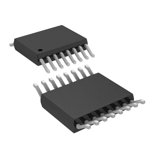
- Part No.:
- LTC6820HMS#3ZZPBF
- Manufacturer:
- Analog Devices Inc.
- Category:
- Specialized
- Package:
- 16-TFSOP (0.118", 3.00mm Width)
- Datasheet:
-
 LTC6820HMS#3ZZPBF.pdf
- Description:
- IC INTERFACE SPECIALIZED 16MSOP
- Quantity:
- Payment:

- Shipping:

Inventory:154
Please send an inquiry. Send us your inquiry, and we will respond immediately.
Product details
Overview
LTC6820HMS#3ZZPBF from Analog Devices is an isoSPI isolated bidirectional communications interface IC that bridges SPI signals across galvanic isolation barriers using a single twisted-pair cable. It operates from 2.7V to 5.5V, supports 1Mbps data rate over up to 100m CAT-5 cable, and features ultralow 2µA idle current, AEC-Q100 qualification (H-grade), and ISO26262 system compliance - deployed in automotive battery monitoring systems for high-noise, high-reliability cell voltage acquisition.
For engineers reviewing the LTC6820HMS#3ZZPBF datasheet, LTC6820HMS#3ZZPBF pinout, LTC6820HMS#3ZZPBF application, or LTC6820HMS#3ZZPBF equivalent, key selection criteria include its 16-pin MSOP package with automotive-grade temperature range (–40°C to 125°C), configurable noise immunity via IBIAS/ICMP resistor network, wake-up detection on IP/IM differential input, and compatibility with standard pulse transformers without center tap.
Technical Context
The LTC6820HMS#3ZZPBF implements a transformer-coupled isoSPI physical layer using matched source/sink current drivers on IP/IM pins and precision window comparators on the receiver side. Its bidirectional protocol encodes CS, SCK, MOSI, and MISO transitions into symmetric ±VA pulse pairs (short for data, long for chip select), eliminating DC bias and enabling robust operation in EMI-heavy environments.
Configuration is hardware-driven: MSTR pin selects master/slave role; PHA/POL pins set SPI mode (0–3); SLOW pin enables timing relaxation for ≤200kHz clocks; IBIAS and ICMP pins jointly configure drive current (20×IB) and comparator threshold (0.5×VICMP) via external resistor divider - allowing optimization for cable length, signal-to-noise ratio, and power consumption.
Key Specifications
| Parameter | Value and Actual Design Meaning |
|---|---|
| Isolation Method | Galvanic isolation via external pulse transformer; no center tap required due to matched current drive. |
| Data Rate | Up to 1Mbps over 100m twisted pair (CAT-5 assumed); derated for longer cables per propagation delay. |
| Supply Range | VDD = 2.7V–5.5V; VDDS = 1.7V–5.5V for independent level shifting of SPI I/O logic. |
| Idle Current | 1µA (MSTR = VDD) or 2µA (MSTR = 0V) - enables ultra-low-power sleep in battery-monitoring nodes. |
| Operating Temp | –40°C to +125°C (H-grade, automotive qualified); validated per AEC-Q100 Grade 0. |
| Wake-Up Latency | <8µs after CS falling edge (master) or IP/IM activity (slave); supports rapid system responsiveness. |
| Logic Compatibility | Interfaces to 1.7V–5.5V logic families; VIH/VIL thresholds scale with VDDS for seamless level translation. |
Pinout & Package
Package: 16-Lead Plastic MSOP (3mm × 4.9mm), exposed pad optional, MSL Level 1, –40°C to +125°C operating range.
| Pin/Terminal | Circuit Role | Design Meaning |
|---|---|---|
| EN | Enable Input | Forces active state when high; otherwise enters IDLE after 5.7ms timeout - critical for power-gating control. |
| MOSI / MISO / SCK / CS | SPI Interface Pins | Open-drain (MOSI/MISO) or push-pull (SCK/CS); referenced to VDDS for level-shifting - decouples logic supply from core VDD. |
| MSTR | Master/Slave Selector | Tie to VDD for master (microcontroller side), GND for slave (remote sensor side) - defines direction of isoSPI traffic flow. |
| IP / IM | Differential Isolated Interface | Current-mode transmitter/receiver pair; drives/reads differential pulses across transformer - no DC path, low EMI. |
| IBIAS / ICMP | Bias & Threshold Control | Resistor-divider network sets drive current (20×IB) and receiver threshold (0.5×VICMP) - enables SNR vs. power trade-off. |
| POL / PHA / SLOW | SPI Timing Configuration | Hardware-selectable SPI mode (0–3) and timing margin (fast/slow clock modes) - eliminates firmware configuration overhead. |
Key Features
| Feature | Design Value |
|---|---|
| Transformer-Coupled isoSPI | Enables >500V isolation with off-the-shelf 1:1 pulse transformers - avoids costly integrated isolators. |
| Configurable Noise Immunity | Adjustable comparator threshold (0.2V–1.5V) and drive current (0.1mA–1mA IBIAS) optimize for EMI-prone battery packs. |
| Ultralow Idle Power | 1–2µA shutdown current extends battery life in always-on BMS monitoring nodes between measurements. |
| AEC-Q100 Qualified | H-grade qualification (–40°C to +125°C) with automotive reliability reports - suitable for ASIL-B/C system integration. |
| No Software Changes Required | Transparent SPI passthrough - microcontrollers and slaves operate unchanged; only physical layer is replaced. |
Applications
| Battery Management Systems (BMS) | Automotive Cell Monitoring |
|---|---|
Use Scenario: Monitoring individual Li-ion cell voltages in high-voltage EV battery packs with >400V common-mode potential between modules. IC Role / Device Role / Timing Role: Isolates MCU-side SPI commands from high-side cell monitor ICs via twisted-pair bus, rejecting ground loops and conducted noise. Use Value: Enables safe, accurate voltage sampling at 125°C ambient while maintaining 1Mbps update rates - critical for thermal runaway prevention. | Use Scenario: Distributed voltage/temperature sensing across multiple battery modules in hybrid powertrain systems. IC Role / Device Role / Timing Role: Acts as slave-side isoSPI transceiver, converting received pulses back to SPI signals for local ADCs and transmitting MISO responses. Use Value: Supports multidrop topology with collision-free short-pulse return signaling - reduces wiring harness weight and cost vs. optocoupler-based solutions. |
| Industrial Energy Storage | Remote Sensor Networks |
Use Scenario: Connecting rack-level BMS controllers to string-level monitoring units in grid-scale lithium iron phosphate (LFP) storage systems. IC Role / Device Role / Timing Role: Master-side isoSPI interface translating MCU SPI to isolated differential pulses over 100m inter-rack cabling. Use Value: Maintains 1Mbps throughput at full 100m distance with <1% bit error rate - ensures real-time state-of-charge synchronization across large installations. | Use Scenario: Isolating environmental sensors (voltage, current, temp) in high-noise industrial motor control cabinets. IC Role / Device Role / Timing Role: Slave device receiving isolated SPI commands and returning digitized sensor data via isoSPI return pulses. Use Value: Eliminates ground bounce-induced measurement errors in 48V–400V DC systems - improves accuracy to ±0.5mV over temperature. |
Equivalent & Alternatives
The following parts are listed as comparable options for similar isolated SPI interface applications.
| Alternative Part | Technical Difference | Application Difference | Selection Advice |
|---|---|---|---|
| ADuM3401CRWZ | Quad-channel digital isolator (non-SPI-specific); requires external SPI controller logic; 25Mbps max, but no built-in isoSPI protocol engine. | Used where discrete isolation of SCK/CS/MOSI/MISO is acceptable; lacks native pulse encoding/decoding and cable-length optimization. | Select when needing higher speed or multi-channel isolation beyond SPI, but accept added firmware complexity and layout overhead. |
| MAX14930AWE+T | Single-channel reinforced isolator with integrated isoSPI-like protocol; supports 15Mbps, but only -40°C to +105°C grade (not AEC-Q100 H-grade). | Targeted at industrial automation; lacks automotive qualification and 125°C operation required for under-hood BMS deployment. | Choose for non-automotive high-speed isolated SPI where extended temperature range is not mandatory. |
Compared with ADuM3401CRWZ and MAX14930AWE+T, the LTC6820HMS#3ZZPBF uniquely combines AEC-Q100 H-grade qualification, native isoSPI protocol handling, and 100m cable support in a single-chip solution - reducing BOM count, PCB area, and validation effort for automotive battery monitoring.
Availability
LTC6820HMS#3ZZPBF is available at Aetrix Electronics and suitable for automotive battery management systems, industrial energy storage monitoring, and remote sensor networks requiring stable component supply with automotive-grade reliability and long-term lifecycle support.
Supply support for LTC6820HMS#3ZZPBF includes scheduled delivery planning, volume procurement assistance, BOM continuity management, traceable sourcing, and lifecycle availability coordination for OEM customers, industrial embedded developers, connected-device designers, and electronics production programs.
Manufacturer
Analog Devices, Inc. is a global leader in high-performance analog, mixed-signal, and digital signal processing semiconductors, serving precision instrumentation, industrial automation, and automotive markets.
The LTC6820HMS#3ZZPBF belongs to Analog Devices' isoSPI product line, engineered specifically for high-reliability, transformer-isolated communication in electric vehicle battery monitoring and other safety-critical distributed sensing applications.
FAQ
What is the primary function of the LTC6820HMS#3ZZPBF in a battery management system?
The LTC6820HMS#3ZZPBF serves as an isoSPI isolated communications interface that enables bidirectional SPI signal transmission across a galvanic isolation barrier using a single twisted-pair cable. In a BMS, it connects the main MCU to high-side cell monitoring ICs, rejecting ground loop noise and supporting reliable operation at up to 125°C ambient temperature - a core requirement for automotive traction battery monitoring.
Does the LTC6820HMS#3ZZPBF require external components to operate, and if so, which ones are mandatory?
Yes, the LTC6820HMS#3ZZPBF requires three mandatory external components: a resistor divider (RB1 + RB2) between IBIAS and GND to set drive current and comparator threshold; a termination resistor (RM = 100Ω typical) across the twisted-pair cable; and a pulse transformer (1:1, center-tap not required) bridging the isolation barrier. Optional components include bypass capacitors (≥0.01µF) on VDD and VDDS.
How does the LTC6820HMS#3ZZPBF achieve AEC-Q100 qualification, and what does the #3ZZ suffix indicate?
The #3ZZ suffix on LTC6820HMS#3ZZPBF denotes Analog Devices' controlled manufacturing process for automotive applications, including enhanced screening, traceability, and reliability testing per AEC-Q100 Grade 0 (–40°C to +125°C). This version undergoes additional qualification beyond standard commercial parts - confirmed by Automotive Reliability Reports available through Analog Devices' sales representatives.
Can the LTC6820HMS#3ZZPBF support multidrop configurations, and how is bus contention avoided?
Yes, the LTC6820HMS#3ZZPBF supports multidrop slave configurations. Bus contention is avoided because only the master transmits long pulses (CS control), while slaves transmit only short –1 pulses (for MISO = 0) - never short +1 or long pulses. This unidirectional return channel design prevents collisions, enabling multiple LTC6820HMS#3ZZPBF slaves on one twisted-pair bus without arbitration logic.
What is the role of the SLOW pin on the LTC6820HMS#3ZZPBF, and when should it be asserted?
The SLOW pin on the LTC6820HMS#3ZZPBF disables high-speed timing constraints to accommodate slower slave devices or marginal signal integrity. It must be tied to VDD when the SPI clock frequency is ≤200kHz or when slave timing margins (e.g., t12, t14) cannot be met with default settings - extending setup/hold windows from nanoseconds to microseconds and relaxing rise-time requirements on pull-up resistors.
LTC6820HMS#3ZZPBF Specifications
- Product attributes
- Attribute value
- Manufacturer:
- Analog Devices Inc.
- Series:
- isoSPI
- Package/Case:
- 16-TFSOP (0.118", 3.00mm Width)
- Packaging:
- Tube
- Product Status:
- Active
- Applications:
- Isolated Communications Interface
- Interface:
- SPI
- Voltage - Supply:
- 2.7V ~ 5.5V
- Supplier Device Package:
- 16-MSOP
- Grade:
- Automotive
- Qualification:
- -
- Mounting Type:
- Surface Mount
LTC6820HMS#3ZZPBF FAQ
1.How can I place an order for LTC6820HMS#3ZZPBF through Aetrix?
Please submit a Request for Quotation (RFQ) for LTC6820HMS#3ZZPBF on Aetrix. Our sales agent will provide a competitive quotation and guide you through the order confirmation once you accept the terms.
2.Are the price and stock information for LTC6820HMS#3ZZPBF reliable?
The price and inventory of LTC6820HMS#3ZZPBF are updated periodically and may fluctuate due to market conditions. Stock and pricing data are typically refreshed every 24 hours. Quotation validity for LTC6820HMS#3ZZPBF is usually 5 days.
3.What payment methods are accepted for LTC6820HMS#3ZZPBF?
We accept Wire Transfer, PayPal, Credit Card, Western Union, MoneyGram, and Escrow for LTC6820HMS#3ZZPBF transactions.
Note: Certain payment methods may incur a processing fee.
4.How is shipping managed for LTC6820HMS#3ZZPBF?
LTC6820HMS#3ZZPBF orders can be shipped via leading logistics carriers, including DHL, UPS, FedEx, TNT, or Registered Mail.
Once your LTC6820HMS#3ZZPBF order is processed, you will receive an email with the shipment details and tracking number.
Note: Tracking information may take up to 24 hours to appear. Express delivery typically takes 3–5 business days.
5.How can I obtain technical support or documentation for LTC6820HMS#3ZZPBF?
For technical support, including LTC6820HMS#3ZZPBF datasheets, pinout diagrams, or application guidance, please contact our engineering support team. They can provide detailed documentation and assistance for your LTC6820HMS#3ZZPBF requirements.
6.How does Aetrix verify that LTC6820HMS#3ZZPBF is sourced from the original manufacturer or authorized distributors?
All LTC6820HMS#3ZZPBF products on Aetrix are procured from qualified distributors and authorized channels. Our dedicated quality assurance team conducts strict verification, including traceability checks and, if necessary, third-party testing. This ensures that LTC6820HMS#3ZZPBF meets industry standards.
7.What is the process for return or replacement of LTC6820HMS#3ZZPBF?
All LTC6820HMS#3ZZPBF units undergo pre-shipment inspection (PSI). If there is an issue with LTC6820HMS#3ZZPBF, returns or replacements are accepted under the following conditions:
1.Quantity discrepancies, incorrect items, or visible external defects (such as breakage or corrosion), acknowledged by Aetrix.
2.The issue is reported within 90 days of delivery.
3.The LTC6820HMS#3ZZPBF part is unused and in its original packaging.
Return procedure for LTC6820HMS#3ZZPBF:
1.Submit a request within 90 days.
2.Obtain a Return Material Authorization (RMA) from Aetrix.
LTC6820HMS#3ZZPBF Tags

-
NVT4857UKAZ
NXP Semiconductors

-
TCA8418RTWR
Texas Instruments

-
PCA9546APWR
Texas Instruments

-
MD0100N8-G
Microchip Technology

-
PCA9548APW,118
NXP Semiconductors

-
PCA9540BDP,118
NXP Semiconductors

-
PCA9548APWR
Texas Instruments

-
PCA9546APW,118
NXP Semiconductors

-
PTN3360DBS,518
NXP Semiconductors

-
PCA9546ABS,118
NXP Semiconductors

-
PCA9518PWR
Texas Instruments

-
PCA9545APW,118
NXP Semiconductors
Tech Hub

A practical engineering guide to 3.3V and 5V logic compatibility, input thresholds, resistor dividers, translator ICs, MOSFET level shifting, I2C pull-ups, timing limits and power-sequencing risks.

The 74HC595 uses push-pull logic outputs, while the TPIC6B595 uses 50 V open-drain DMOS sinks for higher-power loads. This guide compares timing, current limits, 3.3 V interfacing, load wiring, thermal…

The 74HC595 converts serial data into eight stable parallel outputs. This guide covers pin functions, shift and storage timing, OE and MR behavior, drive-current limits, cascading, voltage compatibilit…

A technical comparison of level-sensitive latches and edge-triggered flip-flops, covering timing windows, setup and hold limits, master–slave operation, time borrowing, race-through, HDL inference and…

A D latch stores one bit while Enable controls when data can pass. This reference covers gate-level operation, truth tables, transparency, setup and hold timing, LE versus OE, common ICs and practical …

An SR latch stores one bit through cross-coupled feedback. This engineering reference covers NOR and NAND implementations, truth tables, forbidden-state recovery, gated operation, switch debouncing, fa…

Latch circuits retain one bit through feedback. This technical reference covers SR and D latches, truth tables, transparency, timing limits, latch-versus-flip-flop behavior, applications and common log…

An engineering guide to LED driver operation, constant-current and constant-voltage outputs, linear and switching topologies, dimming, IC selection, calculations, replacement compatibility, and fault c…

Operational amplifier guide covering op amp basics, feedback, ideal vs real op amps, common configurations, buffer circuits, offset, bias current, gain-bandwidth, slew rate, rail-to-rail limits and sel…

Jumper cables guide covering safe connection order, red and black clamp placement, final ground connection, cable gauge, length, clamp quality, copper vs CCA cables, jump starter comparison and battery…


