
 My Inquiry
 My Account


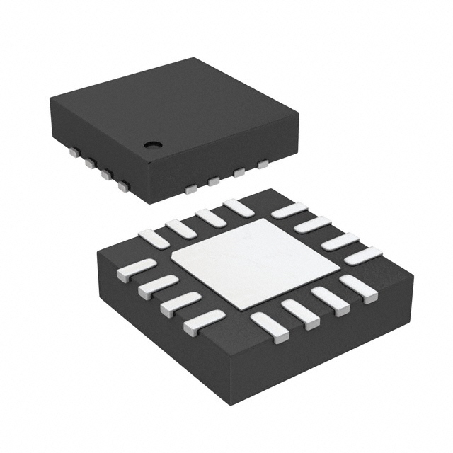
Analog Devices Inc. LTC6820HUD#TRPBF
- Part No.:
- LTC6820HUD#TRPBF
- Manufacturer:
- Analog Devices Inc.
- Category:
- Specialized
- Package:
- 16-WFQFN Exposed Pad
- Datasheet:
-
 LTC6820HUD#TRPBF.pdf
- Description:
- IC INTERFACE SPECIALIZED 16QFN
- Quantity:
- Payment:

- Shipping:

Inventory:5,875
Please send an inquiry. Send us your inquiry, and we will respond immediately.
Product details
Overview
LTC6820HUD#TRPBF from Analog Devices is an isoSPI isolated bidirectional communications interface IC that enables SPI signal transmission across galvanic isolation barriers via a single twisted-pair cable. It operates from 2.7V to 5.5V, supports up to 1Mbps data rate over 100m CAT-5 cable, and delivers ultralow 2µA idle current. It is used in battery monitoring systems where high noise immunity and AEC-Q100 qualification are required.
For engineers reviewing the LTC6820HUD#TRPBF datasheet, LTC6820HUD#TRPBF pinout, LTC6820HUD#TRPBF application, or LTC6820HUD#TRPBF equivalent, key selection criteria include its 16-lead 3mm × 3mm QFN package, –40°C to 125°C automotive-grade temperature range, configurable bias resistor network for signal amplitude/threshold tuning, and compatibility with standard pulse transformers without center-tap requirement.
Technical Context
The LTC6820HUD#TRPBF implements a current-mode differential transmitter with matched source/sink drive (20× IBIAS gain) and precision window comparators on the receiver side. Its isoSPI protocol encodes SPI events-CS transitions, SCK latching edges, and MOSI states-into symmetric ±VA pulse pairs (short for data, long for CS), eliminating DC component and enabling robust noise rejection.
It supports four SPI modes via PHA/POL configuration pins, features automatic wake-up detection (240mV differential threshold, 240ns dwell time), and integrates idle timeout (4–7.5ms) with sub-8µs wake latency. The IBIAS/ICMP resistor divider sets both drive current (0.1mA–1mA) and comparator threshold (0.2V–1.5V), allowing system-level optimization of power vs. noise immunity.
Key Specifications
| Parameter | Value and Actual Design Meaning |
|---|---|
| Data Rate | Up to 1Mbps - enables real-time cell voltage sampling in multi-cell battery packs without sacrificing isolation integrity. |
| Cable Length | Up to 100 meters - supports distributed battery monitoring across large EV chassis or energy storage racks. |
| Idle Current | 2µA maximum - extends standby life in always-on BMS nodes powered by auxiliary supplies. |
| Operating Temp | –40°C to 125°C - meets AEC-Q100 Grade H requirements for under-hood and traction battery applications. |
| Supply Range | VDD = 2.7V–5.5V, VDDS = 1.7V–5.5V - allows independent level-shifting between controller and slave logic domains. |
| Isolation Method | Transformer-coupled differential signaling - achieves hundreds of volts of galvanic isolation using low-cost 1:1 pulse transformers. |
| Wake-Up Threshold | 240mV differential, 240ns dwell - reliably detects valid pulses while rejecting EMI transients common in motor-drive environments. |
Pinout & Package
Package: 16-lead (3mm × 3mm) plastic QFN (UD package), exposed pad (Pin 17) optional GND connection, MSL Level 1, rated for –40°C to 125°C operation.
| Pin/Terminal | Circuit Role | Design Meaning |
|---|---|---|
| MOSI (Pin 1) | SPI Master Out/Slave In Data | Open-drain output when MSTR=0 (slave); input when MSTR=1 (master); requires external VDDS pull-up. |
| MISO (Pin 2) | SPI Master In/Slave Out Data | Open-drain output when MSTR=1 (master); input when MSTR=0 (slave); requires external VDDS pull-up. |
| SCK (Pin 3) | SPI Clock Input/Output | Push-pull output when MSTR=0; input when MSTR=1; no pull-up needed; max VDDS-referenced voltage. |
| CS (Pin 4) | SPI Chip Select Input/Output | Push-pull output when MSTR=0; input when MSTR=1; defines frame boundaries for isoSPI pulse encoding. |
| VDDS (Pin 5) | SPI I/O Power Supply | Sets logic thresholds for CS/SCK/MOSI/MISO/EN; enables level shifting between VDD and peripheral logic voltages. |
| POL/PHA (Pins 6–7) | SPI Mode Configuration | Set static logic levels to select one of four SPI clock polarity/phase modes (Mode 0–3) for full controller compatibility. |
| VDD (Pin 8) | Main Device Supply | Power for internal circuitry and bias generation; bypass capacitor ≥0.01µF required between VDD and GND. |
| IM/IP (Pins 9–10) | Isolated Interface Differential Pair | Transmit/receive differential signals across transformer; matched current drive eliminates center-tap requirement. |
| MSTR (Pin 11) | Master/Slave Selector | Tie to VDD for master-side interface (connects to MCU); tie to GND for slave-side (connects to BMS ADC or other SPI device). |
| SLOW (Pin 12) | Timing Mode Control | Tie to GND for >200kHz operation; tie to VDD for ≤200kHz or marginal timing margin - adjusts internal pulse timers. |
| GND (Pin 13) | Device Ground Reference | Common return for VDD, VDDS, and analog bias circuits; must be low-impedance for stable IBIAS regulation. |
| ICMP (Pin 14) | Comparator Threshold Set | Connected to resistor divider from IBIAS to GND; sets receiver threshold at 0.5× ICMP voltage (0.2V–1.5V range). |
| IBIAS (Pin 15) | Bias Current Reference | Sinks 20× IBIAS current on IP/IM; held at ~2V when enabled; resistor value (2k–20kΩ) sets drive strength and threshold. |
| EN (Pin 16) | Enable Override | Active-high; forces READY state regardless of CS/idle timeout; used for forced wake or debug mode. |
Key Features
| Feature | Design Value |
|---|---|
| Transformer-based galvanic isolation | Enables safe communication across >500V isolation barriers using low-cost 1:1 pulse transformers - no optocouplers or custom magnetics required. |
| Configurable amplitude & threshold | Single resistor divider (IBIAS→GND→ICMP) simultaneously sets drive current (0.1–1mA) and receiver sensitivity (0.2–1.5V), enabling trade-off between EMI robustness and power consumption. |
| Ultralow idle current | 2µA maximum (MSTR=0) or 1µA (MSTR=1) - minimizes quiescent drain in always-connected BMS nodes during vehicle sleep mode. |
| Automatic wake-up detection | Detects valid isoSPI pulses with 240mV differential amplitude and 240ns dwell time, then asserts ready state within 8µs - eliminates software polling overhead. |
| Four SPI mode support | Hardware-configurable PHA/POL pins enable seamless integration with any SPI master or slave, including legacy microcontrollers and ADI's own stack monitors. |
Applications
| Battery Management Systems | Industrial Sensor Networks |
|---|---|
Use Scenario: Monitoring individual cell voltages in 12–100S lithium-ion battery packs for electric vehicles and grid-scale storage. IC Role / Device Role / Timing Role: Isolates MCU SPI commands from high-voltage battery stack; transmits ADC readouts back across barrier using isoSPI pulses. Use Value: Enables accurate, noise-immune communication in high dv/dt environments where optical isolators fail due to CMTI limitations. | Use Scenario: Connecting remote temperature, pressure, or vibration sensors to a central PLC over long cable runs in factory automation. IC Role / Device Role / Timing Role: Converts local SPI sensor outputs into transformer-isolated differential pulses for transmission over 100m twisted pair. Use Value: Eliminates ground loops and common-mode noise in electrically noisy industrial settings while maintaining SPI timing fidelity. |
| Automotive Diagnostics Interfaces | Redundant Safety Controllers |
Use Scenario: Providing isolated diagnostic access to safety-critical ECUs (e.g., airbag controllers, brake modules) via service port. IC Role / Device Role / Timing Role: Bridges service tool SPI to ECU internal bus through reinforced isolation barrier compliant with ISO 26262 ASIL-D requirements. Use Value: Supports field diagnostics without compromising functional safety architecture or requiring redesign of existing ECU PCB layout. | Use Scenario: Synchronizing dual-lockstep MCUs in safety-critical applications such as steering or braking control units. IC Role / Device Role / Timing Role: Transfers status, command, and heartbeat signals between redundant processors across galvanic barrier with deterministic latency. Use Value: Provides fail-safe inter-processor communication path immune to conducted EMI and supply rail disturbances. |
Equivalent & Alternatives
The following parts are listed as comparable options for similar isolated SPI interface applications.
| Alternative Part | Technical Difference | Application Difference | Selection Advice |
|---|---|---|---|
| ADuM3401CRWZ | Quad-channel digital isolator with SPI-tolerant timing; uses iCoupler capacitive isolation; no integrated isoSPI protocol engine. | Requires external logic to encode/decode SPI signals into isolated channels; higher component count and PCB area. | Select when existing design uses discrete isolators and SPI framing is handled in firmware; not drop-in for LTC6820HUD#TRPBF. |
| SI8641ED-B-IS | Quad-channel 5kVrms reinforced digital isolator; supports up to 150Mbps; no native isoSPI mapping or bias configuration. | Needs external level shifters and pulse logic for SPI event translation; lacks automatic wake-up and idle current optimization. | Choose for high-speed general-purpose isolation where protocol-awareness is unnecessary and lowest propagation delay is critical. |
Compared with ADuM3401CRWZ and SI8641ED-B-IS, the LTC6820HUD#TRPBF uniquely integrates isoSPI protocol handling, transformer-friendly current-mode signaling, and ultra-low-power idle operation - reducing BOM count, simplifying layout, and enabling direct replacement of non-isolated SPI links in battery monitoring without firmware changes.
Availability
LTC6820HUD#TRPBF is available at Aetrix Electronics and suitable for battery management systems, automotive diagnostics interfaces, and industrial sensor networks requiring stable component supply with guaranteed automotive-grade temperature performance and long-term lifecycle support.
Supply support for LTC6820HUD#TRPBF includes scheduled delivery planning, volume procurement assistance, BOM continuity management, traceable sourcing, and lifecycle availability coordination for OEM customers, industrial embedded developers, connected-device designers, and electronics production programs.
Manufacturer
Analog Devices, Inc. is a global leader in high-performance analog, mixed-signal, and digital signal processing semiconductors, serving industrial, automotive, communications, and healthcare markets.
The LTC6820HUD#TRPBF belongs to Analog Devices' isoSPI interface product line, engineered specifically for high-reliability, noise-immune communication in battery monitoring and functional safety systems where galvanic isolation and low power are mandatory.
FAQ
What is the primary function of the LTC6820HUD#TRPBF in a battery monitoring system?
The LTC6820HUD#TRPBF serves as an isolated SPI bridge between a microcontroller and high-voltage battery stack peripherals. It converts standard SPI signals (CS, SCK, MOSI, MISO) into transformer-coupled differential pulses for safe, noise-immune communication across galvanic barriers. In the LTC6820HUD#TRPBF, this enables precise cell voltage acquisition in automotive and energy storage BMS without compromising safety or timing integrity.
How does the LTC6820HUD#TRPBF achieve galvanic isolation without optical components?
The LTC6820HUD#TRPBF uses current-mode differential signaling across a standard 1:1 pulse transformer, eliminating the need for optocouplers or custom magnetics. Its matched source/sink drivers on IP/IM pins generate symmetric ±VA pulses, while precision window comparators on the receiver side detect differential thresholds set by the IBIAS/ICMP resistor network. This architecture achieves hundreds of volts of isolation with low EMI and no center-tap requirement - a core feature of the LTC6820HUD#TRPBF.
Can the LTC6820HUD#TRPBF operate with different SPI clock polarities and phases?
Yes, the LTC6820HUD#TRPBF supports all four standard SPI modes via hardware configuration pins PHA and POL. When POL = 0, SCK idles low; when POL = 1, SCK idles high. When PHA = 0, data is latched on the first clock edge; when PHA = 1, it is latched on the second edge. These pins are tied to VDD or GND at power-up to select Mode 0–3 - ensuring full interoperability with diverse SPI masters and slaves in the LTC6820HUD#TRPBF application space.
What is the significance of the SLOW pin on the LTC6820HUD#TRPBF?
The SLOW pin on the LTC6820HUD#TRPBF selects between two internal timing profiles: when tied to GND, it enables high-speed operation (>200kHz SCK) with tight pulse timing (e.g., 50ns half-pulse width); when tied to VDD, it relaxes timing margins for lower-frequency or electrically marginal links (≤200kHz), extending pulse widths to 0.9–1.4µs. This flexibility ensures reliable isoSPI communication across varying cable lengths, transformer characteristics, and noise conditions - a key design adaptation point in the LTC6820HUD#TRPBF.
Does the LTC6820HUD#TRPBF require external components for basic operation?
Yes, the LTC6820HUD#TRPBF requires three essential external components: a resistor divider (RB1 + RB2 = 2k–20kΩ) between IBIAS and GND to set drive current and receiver threshold; a 1:1 pulse transformer with center-tap unused; and 0.01µF bypass capacitors on VDD and VDDS. Optional components include pull-up resistors on MOSI/MISO (open-drain) and termination resistors (e.g., 100Ω) on the twisted-pair cable. These are fundamental to LTC6820HUD#TRPBF functionality - no internal biasing or isolation elements are integrated.
LTC6820HUD#TRPBF Specifications
- Product attributes
- Attribute value
- Manufacturer:
- Analog Devices Inc.
- Series:
- isoSPI
- Package/Case:
- 16-WFQFN Exposed Pad
- Packaging:
- Tape & Reel (TR)
- Product Status:
- Active
- Applications:
- Isolated Communications Interface
- Interface:
- SPI
- Voltage - Supply:
- 2.7V ~ 5.5V
- Supplier Device Package:
- 16-QFN (3x3)
- Grade:
- -
- Qualification:
- -
- Mounting Type:
- Surface Mount
LTC6820HUD#TRPBF FAQ
1.How can I place an order for LTC6820HUD#TRPBF through Aetrix?
Please submit a Request for Quotation (RFQ) for LTC6820HUD#TRPBF on Aetrix. Our sales agent will provide a competitive quotation and guide you through the order confirmation once you accept the terms.
2.Are the price and stock information for LTC6820HUD#TRPBF reliable?
The price and inventory of LTC6820HUD#TRPBF are updated periodically and may fluctuate due to market conditions. Stock and pricing data are typically refreshed every 24 hours. Quotation validity for LTC6820HUD#TRPBF is usually 5 days.
3.What payment methods are accepted for LTC6820HUD#TRPBF?
We accept Wire Transfer, PayPal, Credit Card, Western Union, MoneyGram, and Escrow for LTC6820HUD#TRPBF transactions.
Note: Certain payment methods may incur a processing fee.
4.How is shipping managed for LTC6820HUD#TRPBF?
LTC6820HUD#TRPBF orders can be shipped via leading logistics carriers, including DHL, UPS, FedEx, TNT, or Registered Mail.
Once your LTC6820HUD#TRPBF order is processed, you will receive an email with the shipment details and tracking number.
Note: Tracking information may take up to 24 hours to appear. Express delivery typically takes 3–5 business days.
5.How can I obtain technical support or documentation for LTC6820HUD#TRPBF?
For technical support, including LTC6820HUD#TRPBF datasheets, pinout diagrams, or application guidance, please contact our engineering support team. They can provide detailed documentation and assistance for your LTC6820HUD#TRPBF requirements.
6.How does Aetrix verify that LTC6820HUD#TRPBF is sourced from the original manufacturer or authorized distributors?
All LTC6820HUD#TRPBF products on Aetrix are procured from qualified distributors and authorized channels. Our dedicated quality assurance team conducts strict verification, including traceability checks and, if necessary, third-party testing. This ensures that LTC6820HUD#TRPBF meets industry standards.
7.What is the process for return or replacement of LTC6820HUD#TRPBF?
All LTC6820HUD#TRPBF units undergo pre-shipment inspection (PSI). If there is an issue with LTC6820HUD#TRPBF, returns or replacements are accepted under the following conditions:
1.Quantity discrepancies, incorrect items, or visible external defects (such as breakage or corrosion), acknowledged by Aetrix.
2.The issue is reported within 90 days of delivery.
3.The LTC6820HUD#TRPBF part is unused and in its original packaging.
Return procedure for LTC6820HUD#TRPBF:
1.Submit a request within 90 days.
2.Obtain a Return Material Authorization (RMA) from Aetrix.
LTC6820HUD#TRPBF Tags

-
NVT4857UKAZ
NXP Semiconductors

-
TCA8418RTWR
Texas Instruments

-
PCA9546APWR
Texas Instruments

-
MD0100N8-G
Microchip Technology

-
PCA9548APW,118
NXP Semiconductors

-
PCA9540BDP,118
NXP Semiconductors

-
PCA9548APWR
Texas Instruments

-
PCA9546APW,118
NXP Semiconductors

-
PTN3360DBS,518
NXP Semiconductors

-
PCA9546ABS,118
NXP Semiconductors

-
PCA9518PWR
Texas Instruments

-
PCA9545APW,118
NXP Semiconductors
Tech Hub

A practical engineering guide to 3.3V and 5V logic compatibility, input thresholds, resistor dividers, translator ICs, MOSFET level shifting, I2C pull-ups, timing limits and power-sequencing risks.

The 74HC595 uses push-pull logic outputs, while the TPIC6B595 uses 50 V open-drain DMOS sinks for higher-power loads. This guide compares timing, current limits, 3.3 V interfacing, load wiring, thermal…

The 74HC595 converts serial data into eight stable parallel outputs. This guide covers pin functions, shift and storage timing, OE and MR behavior, drive-current limits, cascading, voltage compatibilit…

A technical comparison of level-sensitive latches and edge-triggered flip-flops, covering timing windows, setup and hold limits, master–slave operation, time borrowing, race-through, HDL inference and…

A D latch stores one bit while Enable controls when data can pass. This reference covers gate-level operation, truth tables, transparency, setup and hold timing, LE versus OE, common ICs and practical …

An SR latch stores one bit through cross-coupled feedback. This engineering reference covers NOR and NAND implementations, truth tables, forbidden-state recovery, gated operation, switch debouncing, fa…

Latch circuits retain one bit through feedback. This technical reference covers SR and D latches, truth tables, transparency, timing limits, latch-versus-flip-flop behavior, applications and common log…

An engineering guide to LED driver operation, constant-current and constant-voltage outputs, linear and switching topologies, dimming, IC selection, calculations, replacement compatibility, and fault c…

Operational amplifier guide covering op amp basics, feedback, ideal vs real op amps, common configurations, buffer circuits, offset, bias current, gain-bandwidth, slew rate, rail-to-rail limits and sel…

Jumper cables guide covering safe connection order, red and black clamp placement, final ground connection, cable gauge, length, clamp quality, copper vs CCA cables, jump starter comparison and battery…


