
 My Inquiry
 My Account


Analog Devices Inc. LTC6904MPMS8#PBF
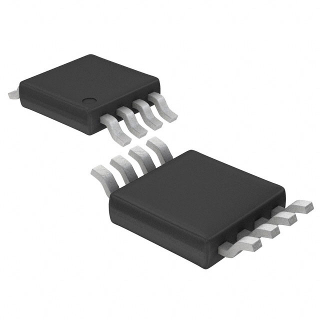
- Part No.:
- LTC6904MPMS8#PBF
- Manufacturer:
- Analog Devices Inc.
- Category:
- Programmable Timers and Oscillators
- Package:
- 8-TSSOP, 8-MSOP (0.118", 3.00mm Width)
- Datasheet:
-
 LTC6904MPMS8#PBF.pdf
- Description:
- IC OSC SILICON PROG 8MSOP
- Quantity:
- Payment:

- Shipping:

Inventory:1,015
Please send an inquiry. Send us your inquiry, and we will respond immediately.
Product details
Overview
LTC6904MPMS8#PBF from Analog Devices (formerly Linear Technology) is an I²C-compatible, digitally programmable oscillator IC delivering a precision square-wave clock output from 1.039 kHz to 68 MHz. It features ±0.5% typical initial frequency accuracy, 10 ppm/°C temperature drift, and operates over –55°C to 125°C in an 8-lead MSOP package. Used for microcontroller clocking, power management timing, and switched-capacitor filter synchronization.
For engineers reviewing the LTC6904MPMS8#PBF datasheet, LTC6904MPMS8#PBF pinout, LTC6904MPMS8#PBF application, or LTC6904MPMS8#PBF equivalent, key selection considerations include its extended temperature grade, I²C interface timing compliance (10–100 kHz), output enable control, dual-clock outputs with configurable phase relationship, and guaranteed monotonic frequency tuning across OCT/DAC settings.
Technical Context
The LTC6904MPMS8#PBF integrates a 34–68 MHz master VCO with a proprietary feedback loop that linearizes digital-to-frequency mapping via a 10-bit DAC and 4-bit octave divider. Its I²C slave interface supports standard-mode (100 kHz) and low-speed (10 kHz) operation with defined tLOW/tHIGH, hold/setup times, and ACK protocol compliance.
Frequency is set by the equation fHz = 2078 × 2(DAC/1024 − OCT), where DAC ∈ [0,1023] and OCT ∈ [0,15]. Output configuration (CLK/CLK enable, phase inversion, low-power mode) is controlled via two CNF bits; OE provides asynchronous output disable with fast recovery.
Key Specifications
| Parameter | Value and Actual Design Meaning |
|---|---|
| Frequency Range | 1.039 kHz to 68 MHz - covers ultra-low-power sleep clocks up to high-speed digital system clocks |
| Initial Accuracy | ±0.5% (typ) at 1.039 kHz - enables reliable boot-time clocking without external calibration |
| Temp Drift | 10 ppm/°C (typ) - ensures stable timing across industrial and automotive extended temperature ranges |
| Supply Range | 2.7 V to 5.5 V - compatible with single-supply 3.3 V and 5 V logic systems |
| I²C Interface | 10–100 kHz SMBus-compliant - interoperable with standard microcontroller I²C peripherals |
| Jitter (1–8 MHz) | <0.4% (typ) peak-to-peak - suitable for ADC sampling clocks and low-jitter digital interfaces |
| Output Enable | Asynchronous OE pin - allows dynamic clock gating without serial reconfiguration |
Pinout & Package
Package: 8-lead plastic MSOP (MS8), 3.0 mm × 3.0 mm × 0.86 mm, –55°C to 125°C operating range.
| Pin/Terminal | Circuit Role | Design Meaning |
|---|---|---|
| GND (Pin 1) | Ground reference | Must connect directly to low-impedance ground plane to minimize supply noise coupling into frequency path |
| SDI (Pin 2) | I²C data input (SDA) | Bi-directional open-drain node; requires external pull-up to V+ for proper I²C signaling |
| SCK (Pin 3) | I²C clock input (SCL) | Input-only clock line; timing must meet tLOW ≥ 4.7 µs and tHIGH ≥ 4.0 µs over full temp range |
| ADR (Pin 4) | I²C address select | Configures LSB of 7-bit slave address (0010110 or 0010111); determines bus uniqueness |
| CLK (Pin 5) | Auxiliary clock output | Programmable frequency output; phase relationship to CLK depends on CNF register setting |
| CLK (Pin 6) | Main clock output | Primary output; can be inverted relative to CLK (Pin 5) or disabled independently via CNF bits |
| OE (Pin 7) | Output enable | Active-high asynchronous control; forces both CLK outputs LOW when deasserted |
| V+ (Pin 8) | Positive supply | Requires local 1 µF || 0.01 µF bypassing within 3 mm to maintain ±0.5% accuracy and low jitter |
Key Features
| Feature | Design Value |
|---|---|
| Dual independent clock outputs | CLK and CLK pins support configurable enable, phase inversion (180°), or powered-down states via CNF[1:0] register bits |
| Monotonic frequency tuning | Guaranteed monotonicity across all OCT/DAC combinations - eliminates frequency glitches during dynamic reprogramming |
| Extended temperature operation | –55°C to 125°C specified performance - qualified for harsh-environment applications including aerospace and downhole instrumentation |
| Low-power shutdown mode | 0.25 mA (typ) supply current at 2.7 V - reduces system power during idle periods without losing register state |
| High-resolution frequency control | 0.1% resolution over full range - enables precise matching to system timing requirements (e.g., USB audio sample rates) |
Applications
| Microcontroller Clock Source | Power Management Timing |
|---|---|
Use Scenario: Providing primary system clock to PIC16F73 or similar 8-bit MCUs during cold-start or brown-out recovery. IC Role / Device Role / Timing Role: Precision, self-contained clock generator replacing crystal + buffer + PLL solutions. Use Value: Eliminates external crystal, load capacitors, and startup delay; guarantees 1.039 kHz power-up default frequency. | Use Scenario: Generating synchronized enable/disable signals for DC-DC converter sequencing in multi-rail power supplies. IC Role / Device Role / Timing Role: Programmable timing reference for voltage supervisor and PMIC control logic. Use Value: Enables adjustable delay intervals (e.g., 10 ms to 1 s) using simple I²C writes-no external RC networks required. |
| Switched-Capacitor Filter Clock | Industrial Sensor Signal Conditioning |
Use Scenario: Driving clock input of LTC1060 or similar precision switched-capacitor filters in anti-aliasing front-ends. IC Role / Device Role / Timing Role: Low-jitter, digitally tunable clock source with tight frequency stability over temperature. Use Value: Maintains filter cutoff accuracy within ±0.5% across –40°C to 125°C, critical for metrology-grade measurements. | Use Scenario: Synchronizing sampling of RTD or thermocouple signal chains in distributed temperature monitoring nodes. IC Role / Device Role / Timing Role: Master timing reference for ΣΔ ADCs and digital isolators in isolated sensor interfaces. Use Value: Provides deterministic jitter <0.4% at 1–8 MHz-ensures ENOB preservation in 24-bit measurement systems. |
Equivalent & Alternatives
The following parts are listed as comparable options for similar digitally programmable oscillator applications.
| Alternative Part | Technical Difference | Application Difference | Selection Advice |
|---|---|---|---|
| LTC6904HMS8#PBF | Same core functionality, but rated for –40°C to 125°C (not –55°C); no MIL-STD or extended cold-spec qualification | Suitable for commercial/industrial systems without sub-zero operational requirement | Select LTC6904MPMS8#PBF only when –55°C startup or continuous operation is mandatory |
| LTC6902CMS8#PBF | 3- or 4-phase output, spread-spectrum modulation enabled; lacks I²C interface (uses SPI); max frequency 68 MHz but lower resolution (1% step size) | Targeted at EMI reduction in motor drives or multi-phase power converters | Choose LTC6904MPMS8#PBF for single/dual-clock precision timing; LTC6902 for phase-aligned, spectrally shaped clocks |
Compared with LTC6904HMS8#PBF, the LTC6904MPMS8#PBF adds verified –55°C functionality and tighter cold-temperature frequency stability, while LTC6902CMS8#PBF trades programmability and interface simplicity for multi-phase capability and EMI suppression-making each optimal for distinct system-level timing architectures.
Availability
LTC6904MPMS8#PBF is available at Aetrix Electronics and suitable for aerospace avionics, downhole oilfield instrumentation, and military-grade embedded controllers requiring stable component supply across extreme temperature excursions.
Supply support for LTC6904MPMS8#PBF includes scheduled delivery planning, volume procurement assistance, BOM continuity management, traceable sourcing, and lifecycle availability coordination for OEM customers, industrial embedded developers, connected-device designers, and electronics production programs.
Manufacturer
Analog Devices, Inc. (acquired Linear Technology in 2017) is a global leader in high-performance analog, mixed-signal, and digital signal processing semiconductors.
The LTC6904MPMS8#PBF belongs to Linear's precision timing family, designed specifically for applications demanding wide-range digital frequency control, extended temperature reliability, and minimal external component count in space- or weight-constrained systems.
FAQ
What is the guaranteed operating temperature range for the LTC6904MPMS8#PBF?
The LTC6904MPMS8#PBF is fully specified and tested over –55°C to 125°C. This extended range is explicitly documented in the Absolute Maximum Ratings and Specified Temperature Range tables of the official datasheet (Rev E, page 2), distinguishing it from standard-grade variants like LTC6904CMS8#PBF (0°C to 70°C) or LTC6904HMS8#PBF (–40°C to 125°C). The LTC6904MPMS8#PBF maintains ±0.5% total frequency accuracy across this full span when loaded with ≤5 pF and supplied at 2.7–5.5 V.
Does the LTC6904MPMS8#PBF support standard I²C addressing and timing?
Yes, the LTC6904MPMS8#PBF implements a fully compliant I²C slave interface with two factory-configurable 7-bit addresses (0010110b and 0010111b) selected by the ADR pin. It meets SMBus timing requirements: clock frequency 10–100 kHz, tLOW ≥ 4.7 µs, tHIGH ≥ 4.0 µs, and data setup/hold times ≥ 250 ns/300 ns. These parameters are guaranteed over the full –55°C to 125°C range and appear in the "Timing Characteristics" table (page 4 of datasheet Rev E).
How does the LTC6904MPMS8#PBF achieve 0.1% frequency resolution?
The LTC6904MPMS8#PBF achieves 0.1% resolution through its dual-parameter frequency equation fHz = 2078 × 2(DAC/1024 − OCT), where the 10-bit DAC (0–1023) provides fine-grained adjustment within each octave, and the 4-bit OCT (0–15) selects coarse frequency bands. This architecture yields >16,000 discrete steps across 1.039 kHz–68 MHz, enabling resolution better than 0.1% at most settings - confirmed by integral nonlinearity <1 LSB and monotonicity guarantees in the "Theory of Operation" section (page 8).
Can both CLK and CLK outputs of the LTC6904MPMS8#PBF be used simultaneously with independent control?
Yes, the LTC6904MPMS8#PBF supports four distinct output configurations via the CNF[1:0] register bits: (0,0) enables both CLK outputs with 180° phase shift; (0,1) disables CLK and enables CLK; (1,0) enables CLK and disables CLK; (1,1) places both outputs in low-power powered-down mode. This per-output control is detailed in Table 2 ("Output Configuration") on page 10 of the datasheet and allows flexible clock tree partitioning without external logic.
What is the power supply bypassing requirement to maintain the stated ±0.5% accuracy for the LTC6904MPMS8#PBF?
To maintain ±0.5% frequency accuracy, the LTC6904MPMS8#PBF requires a minimum 1 µF ceramic capacitor in parallel with a 0.01 µF ceramic capacitor, placed within 3 mm of the V+ (Pin 8) and GND (Pin 1) leads. This dual-capacitor network suppresses supply noise across low and high frequencies, as specified in the "Power Supply Bypass" section (page 9). Failure to meet this requirement may degrade accuracy by up to 0.5% at 68 MHz, especially under dynamic load conditions.
LTC6904MPMS8#PBF Specifications
- Product attributes
- Attribute value
- Manufacturer:
- Analog Devices Inc.
- Series:
- -
- Package/Case:
- 8-TSSOP, 8-MSOP (0.118", 3.00mm Width)
- Packaging:
- Tube
- Product Status:
- Active
- Type:
- Oscillator, Silicon
- Count:
- -
- Frequency:
- 1kHz ~ 68MHz
- Voltage - Supply:
- 2.7V ~ 5.5V
- Current - Supply:
- 7 mA
- Operating Temperature:
- -55°C ~ 125°C
- Supplier Device Package:
- 8-MSOP
- Mounting Type:
- Surface Mount
- Grade:
- -
- Qualification:
- -
LTC6904MPMS8#PBF FAQ
1.How can I place an order for LTC6904MPMS8#PBF through Aetrix?
Please submit a Request for Quotation (RFQ) for LTC6904MPMS8#PBF on Aetrix. Our sales agent will provide a competitive quotation and guide you through the order confirmation once you accept the terms.
2.Are the price and stock information for LTC6904MPMS8#PBF reliable?
The price and inventory of LTC6904MPMS8#PBF are updated periodically and may fluctuate due to market conditions. Stock and pricing data are typically refreshed every 24 hours. Quotation validity for LTC6904MPMS8#PBF is usually 5 days.
3.What payment methods are accepted for LTC6904MPMS8#PBF?
We accept Wire Transfer, PayPal, Credit Card, Western Union, MoneyGram, and Escrow for LTC6904MPMS8#PBF transactions.
Note: Certain payment methods may incur a processing fee.
4.How is shipping managed for LTC6904MPMS8#PBF?
LTC6904MPMS8#PBF orders can be shipped via leading logistics carriers, including DHL, UPS, FedEx, TNT, or Registered Mail.
Once your LTC6904MPMS8#PBF order is processed, you will receive an email with the shipment details and tracking number.
Note: Tracking information may take up to 24 hours to appear. Express delivery typically takes 3–5 business days.
5.How can I obtain technical support or documentation for LTC6904MPMS8#PBF?
For technical support, including LTC6904MPMS8#PBF datasheets, pinout diagrams, or application guidance, please contact our engineering support team. They can provide detailed documentation and assistance for your LTC6904MPMS8#PBF requirements.
6.How does Aetrix verify that LTC6904MPMS8#PBF is sourced from the original manufacturer or authorized distributors?
All LTC6904MPMS8#PBF products on Aetrix are procured from qualified distributors and authorized channels. Our dedicated quality assurance team conducts strict verification, including traceability checks and, if necessary, third-party testing. This ensures that LTC6904MPMS8#PBF meets industry standards.
7.What is the process for return or replacement of LTC6904MPMS8#PBF?
All LTC6904MPMS8#PBF units undergo pre-shipment inspection (PSI). If there is an issue with LTC6904MPMS8#PBF, returns or replacements are accepted under the following conditions:
1.Quantity discrepancies, incorrect items, or visible external defects (such as breakage or corrosion), acknowledged by Aetrix.
2.The issue is reported within 90 days of delivery.
3.The LTC6904MPMS8#PBF part is unused and in its original packaging.
Return procedure for LTC6904MPMS8#PBF:
1.Submit a request within 90 days.
2.Obtain a Return Material Authorization (RMA) from Aetrix.
LTC6904MPMS8#PBF Tags

-
NE555DR
Texas Instruments
-
SA555DR
Texas Instruments
-
NA555DR
Texas Instruments
-
SE555DR
Texas Instruments

-
NE555P
Texas Instruments

-
CD4541BM96
Texas Instruments

-
CD4541BE
Texas Instruments
-
TLC555QDR
Texas Instruments
-
TLC555IDR
Texas Instruments
-
TLC555QDRQ1
Texas Instruments

-
TPL5010DDCR
Texas Instruments
-
TLC555CP
Texas Instruments
Tech Hub

A practical engineering guide to 3.3V and 5V logic compatibility, input thresholds, resistor dividers, translator ICs, MOSFET level shifting, I2C pull-ups, timing limits and power-sequencing risks.

The 74HC595 uses push-pull logic outputs, while the TPIC6B595 uses 50 V open-drain DMOS sinks for higher-power loads. This guide compares timing, current limits, 3.3 V interfacing, load wiring, thermal…

The 74HC595 converts serial data into eight stable parallel outputs. This guide covers pin functions, shift and storage timing, OE and MR behavior, drive-current limits, cascading, voltage compatibilit…

A technical comparison of level-sensitive latches and edge-triggered flip-flops, covering timing windows, setup and hold limits, master–slave operation, time borrowing, race-through, HDL inference and…

A D latch stores one bit while Enable controls when data can pass. This reference covers gate-level operation, truth tables, transparency, setup and hold timing, LE versus OE, common ICs and practical …

An SR latch stores one bit through cross-coupled feedback. This engineering reference covers NOR and NAND implementations, truth tables, forbidden-state recovery, gated operation, switch debouncing, fa…

Latch circuits retain one bit through feedback. This technical reference covers SR and D latches, truth tables, transparency, timing limits, latch-versus-flip-flop behavior, applications and common log…

An engineering guide to LED driver operation, constant-current and constant-voltage outputs, linear and switching topologies, dimming, IC selection, calculations, replacement compatibility, and fault c…

Operational amplifier guide covering op amp basics, feedback, ideal vs real op amps, common configurations, buffer circuits, offset, bias current, gain-bandwidth, slew rate, rail-to-rail limits and sel…

Jumper cables guide covering safe connection order, red and black clamp placement, final ground connection, cable gauge, length, clamp quality, copper vs CCA cables, jump starter comparison and battery…


