
 My Inquiry
 My Account


Analog Devices Inc. LTC6930HDCB-5.00#TRMPBF
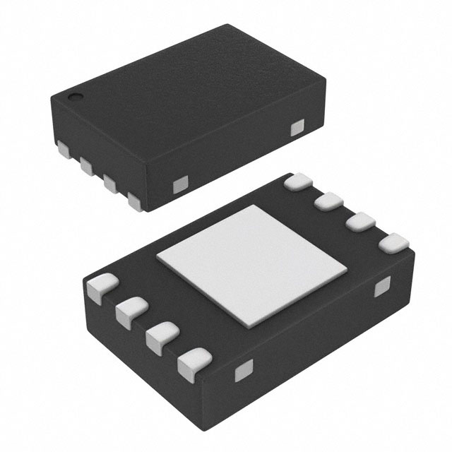
- Part No.:
- LTC6930HDCB-5.00#TRMPBF
- Manufacturer:
- Analog Devices Inc.
- Category:
- Programmable Timers and Oscillators
- Package:
- 8-WFDFN Exposed Pad
- Datasheet:
-
 LTC6930HDCB-5.00#TRMPBF.pdf
- Description:
- IC OSC SILICON 5MHZ 8-DFN
- Quantity:
- Payment:

- Shipping:

Inventory:2,201
Please send an inquiry. Send us your inquiry, and we will respond immediately.
Product details
Overview
LTC6930HDCB-5.00#TRMPBF from Analog Devices (formerly Linear Technology) is a digitally controlled silicon oscillator with factory-set 5.000000MHz master frequency, selectable via DIV pins across eight output frequencies from 39.0625kHz to 5.000MHz. It delivers ±0.1% frequency accuracy over –40°C to 125°C, consumes 124µA typical supply current at 3V/5MHz, and features <110µs power-on delay - ideal for high-reliability industrial timing in harsh-temperature environments.
For engineers reviewing the LTC6930HDCB-5.00#TRMPBF datasheet, LTC6930HDCB-5.00#TRMPBF pinout, LTC6930HDCB-5.00#TRMPBF application, or LTC6930HDCB-5.00#TRMPBF equivalent, key selection criteria include its H-grade temperature range, DFN-8 (2mm × 3mm) package with exposed thermal pad, RMS period jitter of 180ps at 5MHz, and digital frequency division without external components.
Technical Context
The LTC6930HDCB-5.00#TRMPBF implements a proprietary switched-capacitor feedback loop to stabilize its internal 5.000000MHz master oscillator against voltage and temperature variation. Its three CMOS-compatible DIV inputs (DIVA/DIVB/DIVC) configure binary dividers from 1 to 128, enabling precise frequency synthesis without crystal load tuning or trimming.
Internal dual V+ supply routing isolates the oscillator core from output driver noise, while the 40Ω CMOS output stage ensures clean signal integrity into 5pF loads. The device operates from 1.7V to 5.5V with regulated internal biasing, yielding only 0.07%/V supply-induced frequency drift and 0.001%/°C drift in the DFN package.
Key Specifications
| Parameter | Value and Actual Design Meaning |
|---|---|
| Output Frequency Range | 39.0625kHz to 5.000MHz (8 factory-selectable divisions of 5MHz master) |
| Frequency Accuracy | ±0.1% max over –40°C to 125°C (LTC6930H grade) |
| Supply Current | 124µA typical at 3V/5MHz; 190µA typical at 3V/39.0625kHz |
| RMS Period Jitter | 180ps at 5.000MHz, V+ = 3V, CLOAD = 5pF |
| Start-Up Time | <110µs from valid V+ to first accurate output cycle |
| Operating Voltage | 1.7V to 5.5V single supply - supports Li-ion or dual AA battery operation |
| Package | 8-lead DFN (2mm × 3mm) with exposed thermal pad soldered to GND |
Pinout & Package
8-lead plastic DFN package (2mm × 3mm), thermally enhanced with exposed pad (Pin 9) requiring solder connection to ground plane. Pin 1 marked by bar; top-side marking "LCKV" identifies LTC6930HDCB-5.00.
| Pin/Terminal | Circuit Role | Design Meaning |
|---|---|---|
| V+ (Pins 1, 8) | Positive supply input | Dual supply pins reduce supply impedance; each requires local 0.1µF ceramic bypass to adjacent GND |
| GND (Pins 2, 6) | Ground reference | Must be connected to low-inductance ground plane and to exposed pad (Pin 9) |
| DIVA, DIVB, DIVC (Pins 3, 4, 5) | Digital frequency divider select | CMOS inputs (VIL ≤ 1.25V, VIH ≥ 1.4V); set division ratio 1–128 per Table 1 |
| OUT (Pin 7) | CMOS clock output | 40Ω series resistance; drives 5pF load; held low during start-up; glitch-free on DIV changes |
| Exposed Pad (Pin 9) | Thermal & electrical ground | Required for thermal dissipation and EMI reduction; must be soldered to PCB GND plane |
Key Features
| Feature | Design Value |
|---|---|
| Digital frequency selection | Three logic inputs configure 8 discrete output frequencies without external components or trimming |
| Ultra-low power operation | 124µA typical at full 5MHz output enables multi-year battery life in duty-cycled systems |
| High-temperature reliability | Guaranteed performance from –40°C to +125°C (H-grade) with 0.001%/°C frequency drift in DFN |
| Fast, clean start-up | <110µs delay with output held low - eliminates system boot glitches in microcontroller clock domains |
| No-load frequency stability | ±0.1% initial accuracy and 30ppm/√kHr long-term drift support precision timing over product lifetime |
Applications
| Industrial Sensor Node Timing | Automotive Body Control Module Clock |
|---|---|
Use Scenario: Battery-powered wireless sensor node sampling temperature/pressure every 10 seconds, transmitting via BLE. IC Role / Device Role / Timing Role: Primary system clock source for MCU and ADC, synchronized to low-power sleep/wake cycles. Use Value: 124µA at 5MHz and <110µs start-up minimize active-time energy; ±0.1% accuracy ensures reliable time-stamping across temperature extremes. | Use Scenario: Central body controller managing door locks, lighting, and HVAC using CAN communication. IC Role / Device Role / Timing Role: Master clock for microcontroller and CAN transceiver, operating continuously in under-hood environment. Use Value: H-grade –40°C to +125°C rating and 0.001%/°C drift guarantee stable CAN bit timing without calibration over vehicle lifetime. |
| Medical Portable Diagnostic Device | Energy Meter Real-Time Clock |
Use Scenario: Handheld ultrasound or glucose monitor requiring FDA-compliant timing stability and low EMI. IC Role / Device Role / Timing Role: Low-jitter clock for analog front-end sampling and display controller. Use Value: 180ps RMS jitter at 5MHz and isolated dual-V+ routing prevent signal corruption in sensitive analog paths. | Use Scenario: Smart electricity meter operating unattended for 15+ years in outdoor enclosures. IC Role / Device Role / Timing Role: Precision timing reference for metrology ASIC and RTC subsystem. Use Value: 30ppm/√kHr long-term drift and ±0.1% initial accuracy meet IEC 62053-21 Class 0.2 timing requirements without crystal aging compensation. |
Equivalent & Alternatives
The following parts are listed as comparable options for similar digitally controlled oscillator applications.
| Alternative Part | Technical Difference | Application Difference | Selection Advice |
|---|---|---|---|
| SiT1533AI-H4-33E-32.768D | 32.768kHz fixed-output MEMS oscillator; ±10ppm accuracy; no digital division | Only supports single frequency; lacks programmable division and wide-range voltage operation | Select when fixed low-frequency RTC timing suffices and ultra-low 60nA sleep current is critical |
| MAX7375ETE+T | 3.3V-only operation; ±50ppm accuracy over –40°C to +85°C; no H-grade option | Limited temperature range and lower accuracy make it unsuitable for under-hood or extended-life industrial use | Choose for cost-sensitive consumer applications where 85°C max ambient is sufficient |
Compared with SiT1533AI-H4-33E-32.768D and MAX7375ETE+T, the LTC6930HDCB-5.00#TRMPBF uniquely combines H-grade temperature range, 8-step digital division, and sub-0.1% accuracy - enabling one part to replace multiple crystals across diverse frequency points in mission-critical embedded systems.
Availability
LTC6930HDCB-5.00#TRMPBF is available at Aetrix Electronics and suitable for industrial sensor nodes, automotive body control modules, portable medical diagnostics, smart energy meters, and high-reliability embedded systems requiring stable component supply across extended temperature ranges and long production lifecycles.
Supply support for LTC6930HDCB-5.00#TRMPBF includes scheduled delivery planning, volume procurement assistance, BOM continuity management, traceable sourcing, and lifecycle availability coordination for OEM customers, industrial embedded developers, connected-device designers, and electronics production programs.
Manufacturer
Analog Devices, Inc. (ADI) is a global leader in high-performance analog, mixed-signal, and digital signal processing technologies, acquired Linear Technology in 2017 to strengthen precision timing and power management portfolios.
The LTC6930 series was designed by Linear Technology as a family of ultralow-power, high-accuracy silicon oscillators targeting battery-operated and thermally demanding applications where quartz crystals fail due to shock, vibration, or temperature cycling.
FAQ
What is the guaranteed frequency accuracy of the LTC6930HDCB-5.00#TRMPBF over its full operating temperature range?
The LTC6930HDCB-5.00#TRMPBF guarantees ±0.1% frequency accuracy over its specified operating temperature range of –40°C to +125°C. This specification applies to all eight selectable output frequencies derived from the 5.000000MHz master oscillator and is validated across the full 1.7V to 5.5V supply range. The H-grade qualification ensures this accuracy without derating or additional calibration.
Can the LTC6930HDCB-5.00#TRMPBF generate frequencies outside the standard 39.0625kHz–5.000MHz range listed in Table 1?
No - the LTC6930HDCB-5.00#TRMPBF is factory-programmed with a fixed 5.000000MHz master oscillator and supports only the eight division ratios (1, 2, 4, 8, 16, 32, 64, 128) defined in Table 1. Frequencies such as 1MHz or 2.5MHz are supported; non-integer divisions like 3× or 5× are not possible. Custom master frequencies require ordering a different variant (e.g., LTC6930HDCB-8.19#TRMPBF).
How does the exposed thermal pad (Pin 9) on the LTC6930HDCB-5.00#TRMPBF DFN package affect thermal performance and PCB layout?
The exposed pad (Pin 9) on the LTC6930HDCB-5.00#TRMPBF must be soldered to a PCB ground plane to achieve θJA = 64°C/W and ensure safe operation at maximum ambient temperature. Failure to connect it results in excessive junction temperature rise, potential parametric shift, and reduced reliability. Layout requires thermal vias under the pad connected to inner-layer ground planes, with solder mask opening matching pad dimensions.
What is the maximum capacitive load the LTC6930HDCB-5.00#TRMPBF OUT pin can drive while maintaining specified jitter and start-up performance?
The LTC6930HDCB-5.00#TRMPBF OUT pin is characterized for CLOAD = 5pF (equivalent to two HC logic inputs), where RMS period jitter is specified at 180ps. Driving >5pF increases supply current quadratically (ISUPPLY ≈ CLOAD × VSWING × fOSC) and may degrade jitter; 50pF loading draws ~2.2mA at 5MHz and requires local 0.1µF decoupling at Pins 6/8. Jitter degrades to ~0.25% RMS at 50pF, but start-up time remains <110µs.
Does the LTC6930HDCB-5.00#TRMPBF support dynamic frequency reconfiguration during system operation?
Yes - the LTC6930HDCB-5.00#TRMPBF supports glitch-free, single-cycle frequency reconfiguration via its DIVA/DIVB/DIVC pins. When divider settings change, the output transitions cleanly to the new frequency without runt pulses, slivers, or metastability. This allows real-time clock scaling in power-managed systems, provided setup/hold times (≥10ns) are met and supply voltage remains stable during transition.
LTC6930HDCB-5.00#TRMPBF Specifications
- Product attributes
- Attribute value
- Manufacturer:
- Analog Devices Inc.
- Series:
- -
- Package/Case:
- 8-WFDFN Exposed Pad
- Packaging:
- Tape & Reel (TR)
- Product Status:
- Active
- Type:
- Oscillator, Silicon
- Count:
- -
- Frequency:
- 5MHz
- Voltage - Supply:
- 1.7V ~ 5.5V
- Current - Supply:
- 579 µA
- Operating Temperature:
- -40°C ~ 125°C
- Supplier Device Package:
- 8-DFN (2x3)
- Mounting Type:
- Surface Mount
- Grade:
- -
- Qualification:
- -
LTC6930HDCB-5.00#TRMPBF FAQ
1.How can I place an order for LTC6930HDCB-5.00#TRMPBF through Aetrix?
Please submit a Request for Quotation (RFQ) for LTC6930HDCB-5.00#TRMPBF on Aetrix. Our sales agent will provide a competitive quotation and guide you through the order confirmation once you accept the terms.
2.Are the price and stock information for LTC6930HDCB-5.00#TRMPBF reliable?
The price and inventory of LTC6930HDCB-5.00#TRMPBF are updated periodically and may fluctuate due to market conditions. Stock and pricing data are typically refreshed every 24 hours. Quotation validity for LTC6930HDCB-5.00#TRMPBF is usually 5 days.
3.What payment methods are accepted for LTC6930HDCB-5.00#TRMPBF?
We accept Wire Transfer, PayPal, Credit Card, Western Union, MoneyGram, and Escrow for LTC6930HDCB-5.00#TRMPBF transactions.
Note: Certain payment methods may incur a processing fee.
4.How is shipping managed for LTC6930HDCB-5.00#TRMPBF?
LTC6930HDCB-5.00#TRMPBF orders can be shipped via leading logistics carriers, including DHL, UPS, FedEx, TNT, or Registered Mail.
Once your LTC6930HDCB-5.00#TRMPBF order is processed, you will receive an email with the shipment details and tracking number.
Note: Tracking information may take up to 24 hours to appear. Express delivery typically takes 3–5 business days.
5.How can I obtain technical support or documentation for LTC6930HDCB-5.00#TRMPBF?
For technical support, including LTC6930HDCB-5.00#TRMPBF datasheets, pinout diagrams, or application guidance, please contact our engineering support team. They can provide detailed documentation and assistance for your LTC6930HDCB-5.00#TRMPBF requirements.
6.How does Aetrix verify that LTC6930HDCB-5.00#TRMPBF is sourced from the original manufacturer or authorized distributors?
All LTC6930HDCB-5.00#TRMPBF products on Aetrix are procured from qualified distributors and authorized channels. Our dedicated quality assurance team conducts strict verification, including traceability checks and, if necessary, third-party testing. This ensures that LTC6930HDCB-5.00#TRMPBF meets industry standards.
7.What is the process for return or replacement of LTC6930HDCB-5.00#TRMPBF?
All LTC6930HDCB-5.00#TRMPBF units undergo pre-shipment inspection (PSI). If there is an issue with LTC6930HDCB-5.00#TRMPBF, returns or replacements are accepted under the following conditions:
1.Quantity discrepancies, incorrect items, or visible external defects (such as breakage or corrosion), acknowledged by Aetrix.
2.The issue is reported within 90 days of delivery.
3.The LTC6930HDCB-5.00#TRMPBF part is unused and in its original packaging.
Return procedure for LTC6930HDCB-5.00#TRMPBF:
1.Submit a request within 90 days.
2.Obtain a Return Material Authorization (RMA) from Aetrix.
LTC6930HDCB-5.00#TRMPBF Tags

-
NE555DR
Texas Instruments
-
SA555DR
Texas Instruments
-
NA555DR
Texas Instruments
-
SE555DR
Texas Instruments

-
NE555P
Texas Instruments

-
CD4541BM96
Texas Instruments

-
CD4541BE
Texas Instruments
-
TLC555QDR
Texas Instruments
-
TLC555IDR
Texas Instruments
-
TLC555QDRQ1
Texas Instruments

-
TPL5010DDCR
Texas Instruments
-
TLC555CP
Texas Instruments
Tech Hub

A practical engineering guide to 3.3V and 5V logic compatibility, input thresholds, resistor dividers, translator ICs, MOSFET level shifting, I2C pull-ups, timing limits and power-sequencing risks.

The 74HC595 uses push-pull logic outputs, while the TPIC6B595 uses 50 V open-drain DMOS sinks for higher-power loads. This guide compares timing, current limits, 3.3 V interfacing, load wiring, thermal…

The 74HC595 converts serial data into eight stable parallel outputs. This guide covers pin functions, shift and storage timing, OE and MR behavior, drive-current limits, cascading, voltage compatibilit…

A technical comparison of level-sensitive latches and edge-triggered flip-flops, covering timing windows, setup and hold limits, master–slave operation, time borrowing, race-through, HDL inference and…

A D latch stores one bit while Enable controls when data can pass. This reference covers gate-level operation, truth tables, transparency, setup and hold timing, LE versus OE, common ICs and practical …

An SR latch stores one bit through cross-coupled feedback. This engineering reference covers NOR and NAND implementations, truth tables, forbidden-state recovery, gated operation, switch debouncing, fa…

Latch circuits retain one bit through feedback. This technical reference covers SR and D latches, truth tables, transparency, timing limits, latch-versus-flip-flop behavior, applications and common log…

An engineering guide to LED driver operation, constant-current and constant-voltage outputs, linear and switching topologies, dimming, IC selection, calculations, replacement compatibility, and fault c…

Operational amplifier guide covering op amp basics, feedback, ideal vs real op amps, common configurations, buffer circuits, offset, bias current, gain-bandwidth, slew rate, rail-to-rail limits and sel…

Jumper cables guide covering safe connection order, red and black clamp placement, final ground connection, cable gauge, length, clamp quality, copper vs CCA cables, jump starter comparison and battery…


