
 My Inquiry
 My Account


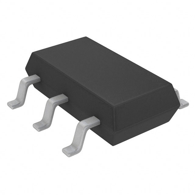
Analog Devices Inc. LTC6993HS6-3#TRPBF
- Part No.:
- LTC6993HS6-3#TRPBF
- Manufacturer:
- Analog Devices Inc.
- Category:
- Multivibrators
- Package:
- SOT-23-6 Thin, TSOT-23-6
- Datasheet:
-
 LTC6993HS6-3#TRPBF.pdf
- Description:
- IC MULTIVIBRATOR 11NS TSOT23-6
- Quantity:
- Payment:

- Shipping:

Inventory:3,542
Please send an inquiry. Send us your inquiry, and we will respond immediately.
Product details
Overview
LTC6993HS6-3#TRPBF from Analog Devices is a falling-edge–triggered, non-retriggerable monostable multivibrator (one-shot pulse generator) in TSOT-23 package, delivering programmable output pulse widths from 1µs to 33.6 seconds with ±4.9% accuracy at NDIV = 1, 2.25V–5.5V supply, and –40°C to 125°C operation-used in missing-pulse detection and high-vibration watchdog timing.
For engineers reviewing the LTC6993HS6-3#TRPBF datasheet, LTC6993HS6-3#TRPBF pinout, LTC6993HS6-3#TRPBF application, or LTC6993HS6-3#TRPBF equivalent, this page provides verified timing parameters, TSOT-23 terminal mapping, polarity-specific trigger behavior, and automotive-grade alternatives for reliable one-shot design in harsh environments.
Technical Context
The LTC6993HS6-3#TRPBF implements a master oscillator with 1µs base period, programmable via ISET current sourced from the SET pin (regulated at 1.00 V ±30 mV), and a 4-bit A/D–controlled divider selecting NDIV values of 1, 8, 64, 512, 4096, 2¹⁵, 2¹⁸, or 2²¹. Its falling-edge TRIG input initiates output pulses without retrigger capability.
Internal polarity control (POL bit) sets output as positive or negative based on DIVCODE; VDIV voltage on the DIV pin determines both NDIV and POL. The device features hysteresis on TRIG (VTRIG_FALLING ≈ 0.48·V+ – 155 mV), 70 µA idle supply current at 10 µs pulse width, and CMOS output capable of ±20 mA drive into 5 pF load.
Key Specifications
| Parameter | Value and Actual Design Meaning |
|---|---|
| Pulse width range | 1 µs to 33.6 s - supports ultra-short timing (e.g., digital glitch detection) and long-duration events (e.g., system reset timeout). |
| Pulse width accuracy | ±4.9% at NDIV = 1 (LTC6993-3/4) - defines worst-case deviation for shortest pulses; improves to ±2.3% for >512 µs. |
| Supply voltage | 2.25 V to 5.5 V - enables direct interface with 3.3 V and 5 V logic, plus low-voltage battery operation down to 2.25 V. |
| Operating temperature | –40°C to 125°C - qualified for under-hood automotive and industrial control applications requiring extended thermal robustness. |
| Output drive | ±20 mA CMOS - sufficient to directly drive LEDs, small relays, or logic inputs without external buffers. |
| Trigger polarity | Falling-edge only - eliminates false triggering from noise-induced rising edges; requires clean signal transitions below tWIDTH = 5 ns. |
| Idle supply current | 70 µA at 10 µs pulse width, 2.25 V - enables multi-year battery life in portable envelope detectors and pulse-width modulated sensors. |
Pinout & Package
Package: 6-Lead Plastic TSOT-23 (0.95 mm height), RoHS-compliant, lead-free finish. Exposed pad not present in S6 package.
| Pin/Terminal | Circuit Role | Design Meaning |
|---|---|---|
| TRIG (Pin 1) | Falling-edge trigger input | Initiates output pulse on voltage transition from high to low; hysteresis prevents chatter on slow edges. |
| GND (Pin 2) | Analog/digital ground reference | Low-inductance connection required; bypass V+ to GND with 0.1 µF ceramic capacitor near pins 1 and 5. |
| SET (Pin 3) | Pulse width programming node | Sinks ISET (1.25–20 µA); VSET regulated at 1.00 V ±30 mV; RSET = 50k–800kΩ sets tMASTER. |
| OUT (Pin 6) | CMOS output driver | Swings rail-to-rail (GND to V+); sources/sinks up to ±20 mA; rise/fall times < 2.7 ns at 2.25 V. |
| V+ (Pin 5) | Positive supply input | Accepts 2.25–5.5 V; must be filtered; powers internal oscillator, A/D, and output stage. |
| DIV (Pin 4) | Divider/polarity configuration input | Voltage divider sets 4-bit DIVCODE (0–15); selects NDIV and output polarity (POL bit); max 100 pF capacitance allowed. |
Key Features
| Feature | Design Value |
|---|---|
| Falling-edge trigger with no retrigger | Ensures single, deterministic pulse per event-ideal for fault-latched systems where repeated triggers must be ignored until full timeout completes. |
| Programmable NDIV up to 2²¹ | Extends base pulse width by factor of 2,097,152, enabling 33.6 s maximum duration using standard 50 kΩ–800 kΩ resistors without external dividers. |
| 1 V regulated SET pin reference | Removes VSET drift impact on timing when using RSET; pulse width depends only on resistor tolerance and inherent IC accuracy. |
| Automotive-grade temperature range | –40°C to 125°C operation with guaranteed performance-meets requirements for engine control, ADAS sensor timing, and powertrain monitoring. |
| Low 70 µA idle current | Minimizes quiescent power in always-on watchdog circuits; enables use in energy-constrained IoT nodes and portable medical devices. |
Applications
| Missing Pulse Detection | Watchdog Timer |
|---|---|
Use Scenario: Monitoring periodic signals (e.g., encoder pulses, CAN bus activity) where absence beyond a defined interval indicates failure. IC Role / Device Role / Timing Role: LTC6993HS6-3#TRPBF acts as a falling-edge–sensitive timeout detector; TRIG tied to signal edge, OUT asserts fault flag after configurable delay. Use Value: Detects signal loss in <1 µs–33.6 s windows with ±4.9% accuracy-enabling precise fault response without microcontroller intervention. | Use Scenario: Ensuring microcontroller or FPGA remains operational in safety-critical automotive ECUs. IC Role / Device Role / Timing Role: LTC6993HS6-3#TRPBF serves as hardware-based reset timer; MCU periodically toggles TRIG; missing toggle causes OUT to assert reset. Use Value: Provides fail-safe, analog-level supervision independent of firmware-guaranteed operation across –40°C to 125°C with no software overhead. |
| Envelope Detection | High-Vibration Timing |
Use Scenario: Extracting amplitude envelope from RF carrier signals in battery-powered wireless sensors. IC Role / Device Role / Timing Role: LTC6993HS6-3#TRPBF generates gated sampling pulses synchronized to carrier zero-crossings via falling-edge TRIG. Use Value: Delivers sub-microsecond jitter (0.45% P-P at NDIV = 1, 2.25 V) and rail-to-rail CMOS output-enabling accurate envelope reconstruction in noisy RF environments. | Use Scenario: Timing critical functions in aerospace actuators or industrial machinery subject to shock (>100 g) and wide thermal swings. IC Role / Device Role / Timing Role: LTC6993HS6-3#TRPBF provides stable, retrigger-free timing for position latching or valve sequencing under mechanical stress. Use Value: Maintains ±0.008%/°C pulse width drift (NDIV ≤ 64) and survives 150°C junction temperature-ensuring reliability where silicon oscillators fail. |
Equivalent & Alternatives
The following parts are listed as comparable options for similar monostable timing applications.
| Alternative Part | Technical Difference | Application Difference | Selection Advice |
|---|---|---|---|
| LTC6993HS6-4#TRPBF | Falling-edge trigger with retrigger capability; identical package, temp range, and timing specs. | Required when system must extend timeout on recurring faults (e.g., intermittent sensor dropout). | Select LTC6993HS6-4#TRPBF only if retrigger behavior is explicitly needed; otherwise LTC6993HS6-3#TRPBF avoids unintended pulse extension. |
| MAX6816EUT+T | Single-channel debouncer (not monostable); fixed 20 ms debounce time; SOT-23-6; –40°C to 125°C. | Used for switch/contact bounce suppression-not programmable pulse generation. | Choose MAX6816EUT+T only for contact debouncing; LTC6993HS6-3#TRPBF offers 1 µs–33.6 s programmability and true one-shot behavior. |
Compared with LTC6993HS6-4#TRPBF and MAX6816EUT+T, the LTC6993HS6-3#TRPBF uniquely delivers non-retriggerable, falling-edge–initiated timing with full 1 µs–33.6 s programmability and automotive-grade stability-making it optimal for deterministic fault-response and watchdog applications where pulse extension must be prohibited.
Availability
LTC6993HS6-3#TRPBF is available at Aetrix Electronics and suitable for automotive engine control units, industrial safety monitors, and portable medical devices requiring stable component supply across extended temperature ranges and long production lifecycles.
Supply support for LTC6993HS6-3#TRPBF includes scheduled delivery planning, volume procurement assistance, BOM continuity management, traceable sourcing, and lifecycle availability coordination for OEM customers, industrial embedded developers, connected-device designers, and electronics production programs.
Manufacturer
Analog Devices is a global leader in high-performance analog, mixed-signal, and digital signal processing semiconductors, serving precision instrumentation, industrial automation, communications, and automotive markets.
The TimerBlox® family-including LTC6993HS6-3#TRPBF-is designed for plug-and-play timing solutions that replace discrete RC networks and microcontroller-based delays in space-, power-, and reliability-constrained systems.
FAQ
What is the trigger behavior of the LTC6993HS6-3#TRPBF?
The LTC6993HS6-3#TRPBF responds exclusively to falling-edge transitions on its TRIG pin and is non-retriggerable-meaning subsequent falling edges during an active output pulse are ignored until the pulse fully completes and the internal circuit re-arms. This ensures exactly one output pulse per qualifying event, critical for fault-locked timing applications.
How is pulse width programmed on the LTC6993HS6-3#TRPBF?
Pulse width on the LTC6993HS6-3#TRPBF is set by two elements: (1) RSET resistor from SET pin to GND (50 kΩ–800 kΩ) controlling master oscillator period, and (2) DIV pin voltage selecting NDIV (1 to 2²¹) and output polarity. The final width is tOUT = NDIV × RSET / 50 kΩ × 1 µs, with accuracy dependent on resistor tolerance and IC specification.
Does the LTC6993HS6-3#TRPBF require external components for basic operation?
Yes-the LTC6993HS6-3#TRPBF requires at minimum: (1) a 0.1 µF ceramic capacitor between V+ and GND for supply decoupling, (2) an RSET resistor from SET to GND to define tMASTER, and (3) a resistor divider on DIV to select NDIV and polarity. No external clock or timing crystal is needed; all timing is self-contained.
What is the maximum output current capability of the LTC6993HS6-3#TRPBF?
The LTC6993HS6-3#TRPBF provides rail-to-rail CMOS output with ±20 mA sourcing/sinking capability at V+ = 2.25 V to 5.5 V. This allows direct driving of LEDs, small solenoids, or logic inputs without external buffers-though series current-limiting resistors are recommended when interfacing with low-impedance loads like LEDs.
Is the LTC6993HS6-3#TRPBF qualified for automotive applications?
Yes-the "H" grade in LTC6993HS6-3#TRPBF denotes qualification across –40°C to 125°C ambient temperature with guaranteed electrical performance, meeting AEC-Q100 stress test requirements for automotive use. It is specified for engine control, body electronics, and ADAS subsystems where reliability under thermal and vibration stress is mandatory.
LTC6993HS6-3#TRPBF Specifications
- Product attributes
- Attribute value
- Manufacturer:
- Analog Devices Inc.
- Series:
- LTC®6993
- Package/Case:
- SOT-23-6 Thin, TSOT-23-6
- Packaging:
- Tape & Reel (TR)
- Product Status:
- Active
- Logic Type:
- Monostable
- Independent Circuits:
- 1
- Schmitt Trigger Input:
- No
- Propagation Delay:
- 11 ns
- Current - Output High, Low:
- 16mA, 16mA
- Voltage - Supply:
- 2.25 V ~ 5.5 V
- Operating Temperature:
- -40°C ~ 125°C
- Grade:
- -
- Qualification:
- -
- Mounting Type:
- Surface Mount
- Supplier Device Package:
- TSOT-23-6
LTC6993HS6-3#TRPBF FAQ
1.How can I place an order for LTC6993HS6-3#TRPBF through Aetrix?
Please submit a Request for Quotation (RFQ) for LTC6993HS6-3#TRPBF on Aetrix. Our sales agent will provide a competitive quotation and guide you through the order confirmation once you accept the terms.
2.Are the price and stock information for LTC6993HS6-3#TRPBF reliable?
The price and inventory of LTC6993HS6-3#TRPBF are updated periodically and may fluctuate due to market conditions. Stock and pricing data are typically refreshed every 24 hours. Quotation validity for LTC6993HS6-3#TRPBF is usually 5 days.
3.What payment methods are accepted for LTC6993HS6-3#TRPBF?
We accept Wire Transfer, PayPal, Credit Card, Western Union, MoneyGram, and Escrow for LTC6993HS6-3#TRPBF transactions.
Note: Certain payment methods may incur a processing fee.
4.How is shipping managed for LTC6993HS6-3#TRPBF?
LTC6993HS6-3#TRPBF orders can be shipped via leading logistics carriers, including DHL, UPS, FedEx, TNT, or Registered Mail.
Once your LTC6993HS6-3#TRPBF order is processed, you will receive an email with the shipment details and tracking number.
Note: Tracking information may take up to 24 hours to appear. Express delivery typically takes 3–5 business days.
5.How can I obtain technical support or documentation for LTC6993HS6-3#TRPBF?
For technical support, including LTC6993HS6-3#TRPBF datasheets, pinout diagrams, or application guidance, please contact our engineering support team. They can provide detailed documentation and assistance for your LTC6993HS6-3#TRPBF requirements.
6.How does Aetrix verify that LTC6993HS6-3#TRPBF is sourced from the original manufacturer or authorized distributors?
All LTC6993HS6-3#TRPBF products on Aetrix are procured from qualified distributors and authorized channels. Our dedicated quality assurance team conducts strict verification, including traceability checks and, if necessary, third-party testing. This ensures that LTC6993HS6-3#TRPBF meets industry standards.
7.What is the process for return or replacement of LTC6993HS6-3#TRPBF?
All LTC6993HS6-3#TRPBF units undergo pre-shipment inspection (PSI). If there is an issue with LTC6993HS6-3#TRPBF, returns or replacements are accepted under the following conditions:
1.Quantity discrepancies, incorrect items, or visible external defects (such as breakage or corrosion), acknowledged by Aetrix.
2.The issue is reported within 90 days of delivery.
3.The LTC6993HS6-3#TRPBF part is unused and in its original packaging.
Return procedure for LTC6993HS6-3#TRPBF:
1.Submit a request within 90 days.
2.Obtain a Return Material Authorization (RMA) from Aetrix.
LTC6993HS6-3#TRPBF Tags

-
SN74LVC1G123DCUR
Texas Instruments

-
CD4047BM96
Texas Instruments
-
SN74LVC1G123DCTR
Texas Instruments

-
CD74HC221M96
Texas Instruments
-
CD14538BE
Texas Instruments
-
SN74LVC1G123YZPR
Texas Instruments
-
SN74LVC1G123DCUT
Texas Instruments
-
MC14538BDR2G
onsemi

-
74VHC123AMX
onsemi
-
LTC6993CS6-2#TRMPBF
Analog Devices Inc.
-
LTC6993CS6-3#TRMPBF
Analog Devices Inc.
-
LTC6993CS6-1#TRMPBF
Analog Devices Inc.
Tech Hub

A practical engineering guide to 3.3V and 5V logic compatibility, input thresholds, resistor dividers, translator ICs, MOSFET level shifting, I2C pull-ups, timing limits and power-sequencing risks.

The 74HC595 uses push-pull logic outputs, while the TPIC6B595 uses 50 V open-drain DMOS sinks for higher-power loads. This guide compares timing, current limits, 3.3 V interfacing, load wiring, thermal…

The 74HC595 converts serial data into eight stable parallel outputs. This guide covers pin functions, shift and storage timing, OE and MR behavior, drive-current limits, cascading, voltage compatibilit…

A technical comparison of level-sensitive latches and edge-triggered flip-flops, covering timing windows, setup and hold limits, master–slave operation, time borrowing, race-through, HDL inference and…

A D latch stores one bit while Enable controls when data can pass. This reference covers gate-level operation, truth tables, transparency, setup and hold timing, LE versus OE, common ICs and practical …

An SR latch stores one bit through cross-coupled feedback. This engineering reference covers NOR and NAND implementations, truth tables, forbidden-state recovery, gated operation, switch debouncing, fa…

Latch circuits retain one bit through feedback. This technical reference covers SR and D latches, truth tables, transparency, timing limits, latch-versus-flip-flop behavior, applications and common log…

An engineering guide to LED driver operation, constant-current and constant-voltage outputs, linear and switching topologies, dimming, IC selection, calculations, replacement compatibility, and fault c…

Operational amplifier guide covering op amp basics, feedback, ideal vs real op amps, common configurations, buffer circuits, offset, bias current, gain-bandwidth, slew rate, rail-to-rail limits and sel…

Jumper cables guide covering safe connection order, red and black clamp placement, final ground connection, cable gauge, length, clamp quality, copper vs CCA cables, jump starter comparison and battery…


