
 My Inquiry
 My Account


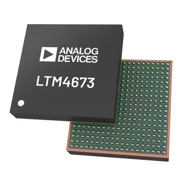
Analog Devices Inc. LTM4673IY#PBF
- Part No.:
- LTM4673IY#PBF
- Manufacturer:
- Analog Devices Inc.
- Category:
- DC DC Converters
- Package:
- -
- Datasheet:
-
 LTM4673IY#PBF.pdf
- Description:
- HIGH DENSITY QUAD OUTPUT MODULE
- Quantity:
- Payment:

- Shipping:

Inventory:4,251
Please send an inquiry. Send us your inquiry, and we will respond immediately.
Product details
Overview
LTM4673IY#PBF from Analog Devices is a quad-output, digital power system management μModule regulator integrating two 12A and two 5A synchronous buck regulators with an on-board 4-channel power system manager. It delivers precise voltage regulation (±0.5% total DC accuracy), real-time telemetry (voltage, current, temperature), and PMBus-compliant sequencing/margining across all four outputs. It serves as a multi-rail point-of-load solution for FPGA, ASIC, and DSP power delivery in telecom and industrial systems.
For engineers reviewing the LTM4673IY#PBF datasheet, LTM4673IY#PBF pinout, LTM4673IY#PBF application, or LTM4673IY#PBF equivalent, key selection criteria include its dual 12A/5A output capability, 400kHz PMBus interface, ±0.5% output voltage regulation, integrated 16-bit ΔΣ ADC, and BGA package thermal performance (θJA = 8.2°C/W).
Technical Context
The LTM4673IY#PBF implements four independent synchronous buck regulators-two optimized for 12A/0.6–3.3V operation and two for 5A/0.6–5.5V-with per-channel digital control via a 400kHz PMBus-compliant I²C interface. Each channel features true differential remote sensing, programmable soft-start, and independent fault thresholds for overvoltage, undervoltage, overcurrent, and temperature.
Its embedded 16-bit ΔΣ ADC continuously monitors input voltage, all four output voltages and currents, and die temperature with ±5% current readback accuracy on 12A channels and ±1% on 5A channels. Fault logging, EEPROM-based configuration storage, and time-based sequencing are handled autonomously by the integrated power system manager without host intervention.
Key Specifications
| Parameter | Value and Actual Design Meaning |
|---|---|
| Input Voltage Range | 4.5V to 15V - supports wide-range industrial and telecom supplies without external pre-regulation. |
| Output Channels | Dual 12A (0.6–3.3V) + dual 5A (0.6–5.5V) - enables full multi-rail FPGA/ASIC core and I/O rail delivery from single module. |
| Output Voltage Accuracy | ±0.5% total DC regulation - ensures stable logic supply under line/load/temperature variation for high-speed digital loads. |
| PMBus Interface | 400kHz I²C-compatible - enables real-time telemetry, margining, and sequencing control using standard board management controllers. |
| ADC Resolution | 16-bit ΔΣ - provides high-precision monitoring of input/output voltages, currents, and temperatures for closed-loop supervision. |
| Package Dimensions | 16mm × 16mm × 4.72mm BGA - compact footprint with bottom-side thermal pad (θJCBOTTOM = 2.2°C/W) for high-power density PCB layouts. |
| Operating Temperature | –40°C to +125°C junction - qualified for extended industrial and telecom base station environments. |
Pinout & Package
The LTM4673IY#PBF is housed in a 361-ball RoHS-compliant BGA package (16mm × 16mm × 4.72mm) with SAC305 solder finish and MSL Level 4 rating. Thermal resistance is θJCTOP = 12.3°C/W and θJCBOTTOM = 2.2°C/W, enabling efficient heat extraction through the bottom thermal pad.
| Pin/Terminal | Circuit Role | Design Meaning |
|---|---|---|
| VIN | Main input power supply | Accepts 4.5V–15V; feeds all four buck stages and internal regulators - requires bulk decoupling per datasheet layout guidelines. |
| VOUT0/VOUT3 | 12A output rails | High-current outputs (0.6–3.3V); each uses dedicated VOSNS+/– for true differential remote sensing to reject PCB IR drop. |
| VOUT1/VOUT2 | 5A output rails | Lower-current outputs (0.6–5.5V); support wider voltage range for I/O or auxiliary rails - also use differential sensing. |
| SDA/SCL | PMBus serial interface | 400kHz I²C bus for bidirectional telemetry, configuration, and fault log access - supports SMBus Alert response and multi-drop addressing. |
| ALERT | Interrupt signaling | Open-drain active-low output asserting on fault, warning, or telemetry-ready events - enables prioritized system-level fault handling. |
| FAULT0/FAULT1 | External fault propagation | Dedicated pins to cascade faults across multiple LTM4673IY#PBF or other μModule devices - supports system-level fault containment. |
| SHARECLK | Frequency synchronization | Allows clock sharing between multiple modules to eliminate beat frequencies and reduce EMI - essential for parallel operation. |
| WP | EEPROM write protection | Hardware pin that disables writes to onboard EEPROM when asserted - prevents accidental corruption of critical configuration data. |
Key Features
| Feature | Design Value |
|---|---|
| Dual 12A + dual 5A integrated regulation | Eliminates need for four discrete POL modules and associated external controllers, reducing BOM count and layout area by >60%. |
| Onboard 16-bit ΔΣ ADC with telemetry | Enables real-time, calibrated readback of all four output voltages/currents and temperature without external sensors or ADCs. |
| Per-channel PMBus programmability | Supports independent voltage trim, sequencing delay/ramp, margining limits, and fault thresholds - no firmware development required. |
| EEPROM-based fault logging | Stores up to 16 fault records with timestamps and parameter snapshots - accelerates field failure root-cause analysis. |
| True differential remote sensing (x4) | Compensates for PCB trace resistance up to 20mΩ per rail - maintains ±0.5% regulation at load point despite layout parasitics. |
| Drop-in compatibility with LTM4671 | Shares identical pinout and footprint - allows upgrade to digital power management without PCB redesign or layout re-spin. |
Applications
| Telecom Baseband Processing | FPGA Power Delivery |
|---|---|
Use Scenario: Powering multi-core baseband processors and high-speed SerDes in 5G macro and small-cell radios. IC Role / Device Role / Timing Role: Quad-rail POL regulator delivering tightly regulated 1.0V/1.2V/1.8V/0.9V supplies with synchronized startup and dynamic load response. Use Value: Maintains <±50mV dynamic deviation during 0–25% load transients, ensuring signal integrity and deterministic timing margins for JESD204B interfaces. |
Use Scenario: Supplying core, auxiliary, and I/O rails for Xilinx Versal or Intel Agilex FPGAs in adaptive compute platforms. IC Role / Device Role / Timing Role: Digital power manager executing precise power-on sequencing (TON_DELAY, TON_RISE), voltage margining, and rail-specific fault responses. Use Value: Enables compliance with FPGA vendor power-up timing specs (e.g., VCCINT before VCCAUX) while providing real-time current telemetry for thermal derating. |
| Industrial PLC CPU Modules | Network Switch ASICs |
Use Scenario: Providing isolated, monitored power to ARM Cortex-A series CPUs and DDR4 memory subsystems in ruggedized PLC controllers. IC Role / Device Role / Timing Role: Multi-rail regulator with EEPROM-stored configuration and fault logging - supports unattended operation and predictive maintenance. Use Value: Onboard fault log captures timestamped overtemperature or overcurrent events, enabling field diagnostics without physical access or debug probes. |
Use Scenario: Delivering 0.85V core, 1.2V I/O, 3.3V management, and 5.0V PHY rails to Broadcom Tomahawk or Marvell Prestera switch ASICs. IC Role / Device Role / Timing Role: High-accuracy POL with ±0.5% regulation and differential sensing - compensates for voltage drop across backplane connectors and long PCB traces. Use Value: Ensures ASIC core voltage remains within JEDEC-specified tolerance (±3%) even under full-switch fabric load and ambient temperature swings. |
Equivalent & Alternatives
The following parts are listed as comparable options for similar multi-rail digital power management applications.
| Alternative Part | Technical Difference | Application Difference | Selection Advice |
|---|---|---|---|
| LTM4671IY#PBF | No integrated power system manager; analog-only control with no PMBus, telemetry, or EEPROM. | Suitable only for fixed-voltage, non-sequenced, non-monitored POL applications. | Select when digital management adds unnecessary cost/complexity and design requires only basic regulation. |
| TPS546D24ARVFT | Single 60A output with PMBus; no multi-rail integration - requires three additional converters for quad-rail operation. | Demands external sequencing IC, telemetry multiplexing, and layout coordination across four ICs. | Select when maximum per-rail current (>12A) or higher efficiency at light load is prioritized over integration and footprint. |
Compared with LTM4673IY#PBF, the LTM4671IY#PBF lacks telemetry and programmability but offers lower cost and simpler validation, while the TPS546D24ARVFT delivers higher single-rail current but increases system complexity, PCB area, and component count for quad-rail designs.
Availability
LTM4673IY#PBF is available at Aetrix Electronics and suitable for telecom infrastructure, industrial PLCs, and high-performance computing applications requiring stable component supply, long-term lifecycle support, and guaranteed traceable sourcing.
Supply support for LTM4673IY#PBF includes scheduled delivery planning, volume procurement assistance, BOM continuity management, traceable sourcing, and lifecycle availability coordination for OEM customers, industrial embedded developers, connected-device designers, and electronics production programs.
Manufacturer
Analog Devices, Inc. is a global leader in high-performance analog, mixed-signal, and digital signal processing semiconductors, serving precision instrumentation, communications, and industrial markets since 1965.
The LTM4673IY#PBF belongs to Analog Devices' μModule regulator family, engineered to integrate power conversion, digital management, and thermal optimization into compact, drop-in power solutions for space-constrained, high-reliability systems.
FAQ
What is the operating temperature range for the LTM4673IY#PBF?
The LTM4673IY#PBF is rated for a junction temperature range of –40°C to +125°C. This specification applies to the full electrical performance envelope, including all four output channels delivering rated current under worst-case airflow and PCB copper conditions. Derating curves for output current versus temperature are provided in the datasheet's Thermal Considerations section, and thermal pads must be properly connected to internal ground planes per recommended layout guidelines to maintain this rating.
Does the LTM4673IY#PBF support parallel operation of output channels?
Yes, the LTM4673IY#PBF supports multichannel parallel operation for increased output current. Its SHARECLK pin enables frequency synchronization across multiple LTM4673IY#PBF units or compatible μModule regulators, eliminating beat frequencies and ensuring interleaved switching. The device also includes dedicated control pins (CONTROL0–3) and configurable DAC outputs (VDAC0–3) to coordinate current sharing and phase alignment - details are specified in the Multichannel Parallel Operation section of the datasheet.
How does the LTM4673IY#PBF handle fault conditions such as overvoltage or overtemperature?
The LTM4673IY#PBF independently monitors all four outputs for overvoltage, undervoltage, overcurrent, and undercurrent, plus input over/undervoltage and die temperature. When a fault threshold is exceeded, it asserts the ALERT pin, logs the event with timestamp and parameter values in onboard EEPROM, and executes user-configurable responses - including latching shutdown, automatic restart, or assertion of FAULT0/FAULT1 for system-level propagation. Fault response modes (e.g., VOUT_OV_FAULT_RESPONSE) are programmable via PMBus commands.
Can the LTM4673IY#PBF be used without connecting the PMBus interface?
Yes, the LTM4673IY#PBF operates fully autonomously without PMBus connectivity. Default configurations stored in EEPROM govern startup voltage, sequencing, and protection thresholds. SDA and SCL pins may be left unconnected or pulled high per datasheet recommendations. However, disabling PMBus forfeits real-time telemetry, dynamic margining, runtime reconfiguration, and fault log retrieval - functionality retained only if the interface is implemented for advanced system management.
What is the purpose of the VDAC pins on the LTM4673IY#PBF?
The VDAC0–VDAC3 pins on the LTM4673IY#PBF are 10-bit digital-to-analog outputs used to inject precise offset voltages into the feedback (FBx) nodes of each regulator channel. This enables software-controlled voltage margining (±5% typical), fine trimming, and servo-based closed-loop regulation. Each VDAC has programmable polarity and buffer gain settings, and its output range is 0–1.38V or 0–2.65V depending on configuration - allowing accurate adjustment of output voltages from 0.6V to 5.5V without external components.
LTM4673IY#PBF Specifications
- Product attributes
- Attribute value
- Manufacturer:
- Analog Devices Inc.
- Series:
- -
- Package/Case:
- -
- Packaging:
- Tray
- Product Status:
- Active
- Type:
- -
- Number of Outputs:
- -
- Voltage - Input (Min):
- -
- Voltage - Input (Max):
- -
- Voltage - Output 1:
- -
- Voltage - Output 2:
- -
- Voltage - Output 3:
- -
- Voltage - Output 4:
- -
- Current - Output (Max):
- -
- Power (Watts):
- -
- Voltage - Isolation:
- -
- Applications:
- -
- Features:
- -
- Operating Temperature:
- -
- Efficiency:
- -
- Grade:
- -
- Qualification:
- -
- Mounting Type:
- -
- Supplier Device Package:
- -
- Control Features:
- -
- Approval Agency:
- -
- Standard Number:
- -
LTM4673IY#PBF FAQ
1.How can I place an order for LTM4673IY#PBF through Aetrix?
Please submit a Request for Quotation (RFQ) for LTM4673IY#PBF on Aetrix. Our sales agent will provide a competitive quotation and guide you through the order confirmation once you accept the terms.
2.Are the price and stock information for LTM4673IY#PBF reliable?
The price and inventory of LTM4673IY#PBF are updated periodically and may fluctuate due to market conditions. Stock and pricing data are typically refreshed every 24 hours. Quotation validity for LTM4673IY#PBF is usually 5 days.
3.What payment methods are accepted for LTM4673IY#PBF?
We accept Wire Transfer, PayPal, Credit Card, Western Union, MoneyGram, and Escrow for LTM4673IY#PBF transactions.
Note: Certain payment methods may incur a processing fee.
4.How is shipping managed for LTM4673IY#PBF?
LTM4673IY#PBF orders can be shipped via leading logistics carriers, including DHL, UPS, FedEx, TNT, or Registered Mail.
Once your LTM4673IY#PBF order is processed, you will receive an email with the shipment details and tracking number.
Note: Tracking information may take up to 24 hours to appear. Express delivery typically takes 3–5 business days.
5.How can I obtain technical support or documentation for LTM4673IY#PBF?
For technical support, including LTM4673IY#PBF datasheets, pinout diagrams, or application guidance, please contact our engineering support team. They can provide detailed documentation and assistance for your LTM4673IY#PBF requirements.
6.How does Aetrix verify that LTM4673IY#PBF is sourced from the original manufacturer or authorized distributors?
All LTM4673IY#PBF products on Aetrix are procured from qualified distributors and authorized channels. Our dedicated quality assurance team conducts strict verification, including traceability checks and, if necessary, third-party testing. This ensures that LTM4673IY#PBF meets industry standards.
7.What is the process for return or replacement of LTM4673IY#PBF?
All LTM4673IY#PBF units undergo pre-shipment inspection (PSI). If there is an issue with LTM4673IY#PBF, returns or replacements are accepted under the following conditions:
1.Quantity discrepancies, incorrect items, or visible external defects (such as breakage or corrosion), acknowledged by Aetrix.
2.The issue is reported within 90 days of delivery.
3.The LTM4673IY#PBF part is unused and in its original packaging.
Return procedure for LTM4673IY#PBF:
1.Submit a request within 90 days.
2.Obtain a Return Material Authorization (RMA) from Aetrix.
LTM4673IY#PBF Tags
-
1S4E_0505S1.5U
GAPTEC Electronic
-
TPS631000DRLR
Texas Instruments
-
XCL209F083DR
Torex Semiconductor Ltd
-
SC202AMLTRT
Semtech Corporation

-
NME1S0505SC
Murata Power Solutions Inc.
-
XCL101A501ER-G
Torex Semiconductor Ltd
-
RFM-0505S
Recom Power
-
TEA 1-0505E
Traco Power
-
MIC33153YHJ-TR
Microchip Technology
-
TEA 1-0505
Traco Power
-
TPSM863252RDXR
Texas Instruments
-
RFB-0505S
Recom Power
Tech Hub

A practical engineering guide to 3.3V and 5V logic compatibility, input thresholds, resistor dividers, translator ICs, MOSFET level shifting, I2C pull-ups, timing limits and power-sequencing risks.

The 74HC595 uses push-pull logic outputs, while the TPIC6B595 uses 50 V open-drain DMOS sinks for higher-power loads. This guide compares timing, current limits, 3.3 V interfacing, load wiring, thermal…

The 74HC595 converts serial data into eight stable parallel outputs. This guide covers pin functions, shift and storage timing, OE and MR behavior, drive-current limits, cascading, voltage compatibilit…

A technical comparison of level-sensitive latches and edge-triggered flip-flops, covering timing windows, setup and hold limits, master–slave operation, time borrowing, race-through, HDL inference and…

A D latch stores one bit while Enable controls when data can pass. This reference covers gate-level operation, truth tables, transparency, setup and hold timing, LE versus OE, common ICs and practical …

An SR latch stores one bit through cross-coupled feedback. This engineering reference covers NOR and NAND implementations, truth tables, forbidden-state recovery, gated operation, switch debouncing, fa…

Latch circuits retain one bit through feedback. This technical reference covers SR and D latches, truth tables, transparency, timing limits, latch-versus-flip-flop behavior, applications and common log…

An engineering guide to LED driver operation, constant-current and constant-voltage outputs, linear and switching topologies, dimming, IC selection, calculations, replacement compatibility, and fault c…

Operational amplifier guide covering op amp basics, feedback, ideal vs real op amps, common configurations, buffer circuits, offset, bias current, gain-bandwidth, slew rate, rail-to-rail limits and sel…

Jumper cables guide covering safe connection order, red and black clamp placement, final ground connection, cable gauge, length, clamp quality, copper vs CCA cables, jump starter comparison and battery…


