
 My Inquiry
 My Account


STMicroelectronics M24C08-FCT6TP/T
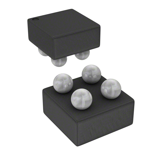
- Part No.:
- M24C08-FCT6TP/T
- Manufacturer:
- STMicroelectronics
- Category:
- Memory
- Package:
- 4-XFBGA, WLCSP
- Datasheet:
-
 M24C08-FCT6TP/T.pdf
- Description:
- IC EEPROM 8KBIT I2C 4WLCSP
- Quantity:
- Payment:

- Shipping:

Inventory:72,454
Please send an inquiry. Send us your inquiry, and we will respond immediately.
Product details
Overview
M24C08-FCT6TP/T from STMicroelectronics is an 8-Kbit I²C-compatible serial EEPROM organized as 1 K × 8 bits, operating from 1.7 V to 5.5 V across –40 °C to +85 °C. It supports 400 kHz and 100 kHz I²C bus modes, features 16-byte page write capability with ≤5 ms write time, and includes hardware write protection via WC pin. It is used in industrial control modules for parameter storage and calibration data retention.
For engineers reviewing the M24C08-FCT6TP/T datasheet, M24C08-FCT6TP/T pinout, M24C08-FCT6TP/T application, or M24C08-FCT6TP/T equivalent, key selection criteria include supply voltage range (1.7–5.5 V), I²C clock compatibility (up to 400 kHz), page size (16 bytes), write endurance (4 million cycles), and package-specific pin mapping (TSSOP8 with E2/SDA/SCL/WC/VCC/VSS).
Technical Context
The M24C08-FCT6TP/T implements a standard I²C slave protocol with start/stop detection, 7-bit device address plus R/W bit, and ACK/NACK handshaking. Its internal architecture includes a page latch, X/Y decoders, sense amplifiers, and HV generator for EEPROM programming - enabling byte and page writes without external high-voltage supply.
It supports three read modes: random address (via dummy write + restart), current address (auto-incremented), and sequential (multi-byte stream with roll-over). Write control (WC) disables all writes when high; E2 sets b3 of device address and is unconnected in TSSOP8 variant per DS9362 Rev 7 Figure 2.
Key Specifications
| Parameter | Value and Actual Design Meaning |
|---|---|
| Memory size | 8 Kbit (1024 × 8), sufficient for firmware configuration, sensor calibration tables, or device ID storage in space-constrained designs. |
| I²C speed | Up to 400 kHz fast-mode operation, enabling sub-250 µs address+data transfer for single-byte writes in real-time systems. |
| Page size | 16 bytes per page - defines maximum contiguous write length before wrap-around; critical for optimizing write latency in logging applications. |
| Write time | ≤5 ms max for byte or page write - determines minimum interval between successive write commands; impacts system responsiveness during parameter updates. |
| Supply range | 1.7 V to 5.5 V (full temp range), supporting direct interface with 1.8 V logic, 3.3 V microcontrollers, and 5 V legacy systems without level shifters. |
| Data retention | 200 years at 55 °C - ensures long-term reliability for medical, industrial, or infrastructure equipment with infrequent field maintenance. |
| Endurance | 4 million write cycles at 25 °C - allows daily reconfiguration over >10 years in embedded controllers managing dynamic settings. |
Pinout & Package
Package: TSSOP8 (DW), 169 mil width, RoHS-compliant and halogen-free (ECOPACK2). Pin 1 marked by notch or dot; pin numbering follows standard counter-clockwise layout from top view.
| Pin/Terminal | Circuit Role | Design Meaning |
|---|---|---|
| 1 (E2) | Chip enable input | Sets b3 of 7-bit device address (1010b); tied to VSS or VCC to select one of four possible I²C addresses on shared bus. |
| 2 (SDA) | Serial data I/O | Open-drain bidirectional line - requires external pull-up; shares bus with other I²C slaves; handles address, data, and ACK/NACK signaling. |
| 3 (SCL) | Serial clock input | Master-generated clock (≤400 kHz); sampled on rising edge for data input; controls timing of all read/write transfers. |
| 4 (WC) | Write control input | Active-high hardware lock - disables all write operations (byte/page) when driven high; floating or low enables writes. |
| 5 (VSS) | Ground reference | Return path for all signals and internal circuitry; must be low-impedance and decoupled near package pins. |
| 6 (NC) | No connect | Not bonded internally; left unconnected on PCB; no electrical function or routing required. |
| 7 (VCC) | Supply voltage | Power source (1.7–5.5 V); requires local 10–100 nF ceramic decoupling capacitor to suppress noise during internal write cycles. |
| 8 (NC) | No connect | Not bonded internally; left unconnected on PCB; no electrical function or routing required. |
Key Features
| Feature | Design Value |
|---|---|
| Wide VCC range (1.7–5.5 V) | Enables direct integration with mixed-voltage systems (e.g., 1.8 V MCU + 5 V analog front-end) without level-shifting circuitry. |
| Hardware write protection (WC pin) | Prevents accidental overwrites during power transients or firmware bugs - critical for safety-critical calibration data integrity. |
| 16-byte page write | Reduces I²C bus occupancy vs. byte writes - cuts total transaction time by ~85% when storing 16-byte sensor records or network keys. |
| Enhanced ESD/latch-up immunity | Withstands ±3 kV HBM ESD and operates reliably under industrial noise conditions - reduces need for external protection components. |
| 200-year data retention | Validated at 55 °C; ensures stored parameters remain intact over full product lifecycle in uncooled enclosures or remote deployments. |
Applications
| Industrial PLC Configuration Storage | Smart Meter Calibration Data |
|---|---|
|
Use Scenario: Storing I/O mapping, scaling factors, and alarm thresholds in programmable logic controllers deployed in factory automation cabinets. IC Role / Device Role / Timing Role: Nonvolatile parameter register accessed during boot and runtime via I²C; retains values across power cycles and brownouts. Use Value: Eliminates need for battery-backed SRAM; supports field recalibration without firmware update; leverages 4M-cycle endurance for daily commissioning logs. |
Use Scenario: Holding meter-specific calibration coefficients (e.g., voltage/current gain, phase offset) updated during factory test and field verification. IC Role / Device Role / Timing Role: Secure, tamper-resistant memory block accessed only during authorized calibration sessions using WC pin disable. Use Value: Ensures metrological accuracy over 10+ years; 200-year retention meets ANSI C12.20 and IEC 62053 standards for revenue-grade meters. |
| Medical Device Settings Backup | Automotive Body Control Module IDs |
|
Use Scenario: Saving user preferences (e.g., display brightness, audio volume), therapy parameters, and usage history in portable diagnostic devices. IC Role / Device Role / Timing Role: Low-power I²C slave interfaced to ARM Cortex-M0+ MCU; powered from same 3.3 V rail as main SoC. Use Value: Operates down to 1.7 V - maintains functionality during Li-ion battery discharge to 3.0 V; 8 Kbit capacity stores >200 distinct settings. |
Use Scenario: Storing unique vehicle identifiers (VIN segment), module production date, and software version in door modules and seat controllers. IC Role / Device Role / Timing Role: Boot-time configuration loader for CAN gateway firmware; accessed once per power-on reset. Use Value: TSSOP8 package fits tight PCB spaces; ECOPACK2 compliance satisfies automotive RoHS/ELV requirements; -40 °C to +85 °C rating matches under-hood thermal profile. |
Equivalent & Alternatives
The following parts are listed as comparable options for similar serial EEPROM applications.
| Alternative Part | Technical Difference | Application Difference | Selection Advice |
|---|---|---|---|
| AT24C08D-SSHM-T (Microchip) | Same 8 Kbit size, 1.7–5.5 V, but uses 1 MHz I²C fast-mode-plus; lacks WC pin - write protection relies on software lock or external GPIO. | Preferred where higher throughput is needed and MCU firmware can manage write-enable sequencing. | Select if system already uses Microchip EEPROM portfolio and requires faster bus speeds; verify SDA/SCL drive strength compatibility. |
| BR24G08NUX-10 (ROHM) | 8 Kbit, 1.6–5.5 V, supports 1 MHz I²C; includes WP pin (functionally identical to WC) and built-in write cycle interrupt (INT pin) not present in M24C08-F. | Suitable for designs needing hardware notification of write completion without polling ACK. | Choose when reducing CPU overhead during EEPROM writes is critical; note BR24G08NUX-10 uses DFN8 package - check board layout compatibility. |
Compared with AT24C08D-SSHM-T and BR24G08NUX-10, the M24C08-FCT6TP/T offers proven industrial temperature stability and ECOPACK2 compliance out-of-box, while trading off interrupt signaling and ultra-fast I²C for lower cost and broader legacy design reuse.
Availability
M24C08-FCT6TP/T is available at Aetrix Electronics and suitable for industrial PLCs, smart meters, medical diagnostics, and automotive body control modules requiring stable component supply, long-lifecycle support, and RoHS-compliant packaging.
Supply support for M24C08-FCT6TP/T includes scheduled delivery planning, volume procurement assistance, BOM continuity management, traceable sourcing, and lifecycle availability coordination for OEM customers, industrial embedded developers, connected-device designers, and electronics production programs.
Manufacturer
STMicroelectronics is a global semiconductor leader headquartered in Geneva, Switzerland, designing and manufacturing microcontrollers, power ICs, sensors, and memory solutions for industrial, automotive, and consumer markets.
The M24C08-F belongs to ST's serial EEPROM product line, engineered specifically for robust, low-power, I²C-based nonvolatile storage in harsh environments - emphasizing voltage flexibility, data integrity, and long-term reliability over raw speed.
FAQ
What is the function of the E2 pin on M24C08-FCT6TP/T?
The E2 pin sets bit b3 of the 7-bit I²C device address (1010b), allowing up to four M24C08 devices on the same bus. In the TSSOP8 package, it must be hard-wired to VSS or VCC - floating is not recommended as it reads as low. This pin is unconnected in DFN5 and WLCSP variants.
Can M24C08-FCT6TP/T operate at 1.6 V?
No - the M24C08-FCT6TP/T is rated for 1.7 V to 5.5 V across the full –40 °C to +85 °C range. While the base M24C08-F supports 1.6 V under restricted temperature conditions (e.g., TA ≥ 0 °C for write operations), this specific TSSOP8 variant (CT6TP/T) does not guarantee 1.6 V functionality per DS9362 Rev 7 Tables 8 and 16.
How does the WC pin affect read operations?
The WC pin has no effect on read operations: reads proceed normally regardless of WC state (high, low, or floating). Only write instructions (byte or page) are blocked when WC is driven high; read instructions always return valid data and increment the internal address counter.
Is the TSSOP8 package of M24C08-FCT6TP/T pin-compatible with SO8N?
No - although both are 8-pin packages, TSSOP8 (DW) and SO8N (MN) have different pinouts. In TSSOP8, pins 6 and 8 are NC; in SO8N, those positions carry functional signals. Direct PCB replacement requires layout revision. Refer to DS9362 Figure 2 (TSSOP8) vs. Figure 19 (SO8N) for exact mapping.
M24C08-FCT6TP/T Specifications
- Product attributes
- Attribute value
- Manufacturer:
- STMicroelectronics
- Series:
- -
- Package/Case:
- 4-XFBGA, WLCSP
- Packaging:
- Tape & Reel (TR)
- Product Status:
- Active
- Programmable:
- Not Verified
- Memory Type:
- Non-Volatile
- Memory Format:
- EEPROM
- Technology:
- EEPROM
- Memory Size:
- 8Kbit
- Memory Organization:
- 1K x 8
- Memory Interface:
- I2C
- Clock Frequency:
- 400 kHz
- Write Cycle Time - Word, Page:
- 5ms
- Access Time:
- 900 ns
- Voltage - Supply:
- 1.7V ~ 5.5V
- Operating Temperature:
- -40°C ~ 85°C (TA)
- Grade:
- -
- Qualification:
- -
- Mounting Type:
- Surface Mount
- Supplier Device Package:
- 4-WLCSP (0.70x0.71)
M24C08-FCT6TP/T FAQ
1.How can I place an order for M24C08-FCT6TP/T through Aetrix?
Please submit a Request for Quotation (RFQ) for M24C08-FCT6TP/T on Aetrix. Our sales agent will provide a competitive quotation and guide you through the order confirmation once you accept the terms.
2.Are the price and stock information for M24C08-FCT6TP/T reliable?
The price and inventory of M24C08-FCT6TP/T are updated periodically and may fluctuate due to market conditions. Stock and pricing data are typically refreshed every 24 hours. Quotation validity for M24C08-FCT6TP/T is usually 5 days.
3.What payment methods are accepted for M24C08-FCT6TP/T?
We accept Wire Transfer, PayPal, Credit Card, Western Union, MoneyGram, and Escrow for M24C08-FCT6TP/T transactions.
Note: Certain payment methods may incur a processing fee.
4.How is shipping managed for M24C08-FCT6TP/T?
M24C08-FCT6TP/T orders can be shipped via leading logistics carriers, including DHL, UPS, FedEx, TNT, or Registered Mail.
Once your M24C08-FCT6TP/T order is processed, you will receive an email with the shipment details and tracking number.
Note: Tracking information may take up to 24 hours to appear. Express delivery typically takes 3–5 business days.
5.How can I obtain technical support or documentation for M24C08-FCT6TP/T?
For technical support, including M24C08-FCT6TP/T datasheets, pinout diagrams, or application guidance, please contact our engineering support team. They can provide detailed documentation and assistance for your M24C08-FCT6TP/T requirements.
6.How does Aetrix verify that M24C08-FCT6TP/T is sourced from the original manufacturer or authorized distributors?
All M24C08-FCT6TP/T products on Aetrix are procured from qualified distributors and authorized channels. Our dedicated quality assurance team conducts strict verification, including traceability checks and, if necessary, third-party testing. This ensures that M24C08-FCT6TP/T meets industry standards.
7.What is the process for return or replacement of M24C08-FCT6TP/T?
All M24C08-FCT6TP/T units undergo pre-shipment inspection (PSI). If there is an issue with M24C08-FCT6TP/T, returns or replacements are accepted under the following conditions:
1.Quantity discrepancies, incorrect items, or visible external defects (such as breakage or corrosion), acknowledged by Aetrix.
2.The issue is reported within 90 days of delivery.
3.The M24C08-FCT6TP/T part is unused and in its original packaging.
Return procedure for M24C08-FCT6TP/T:
1.Submit a request within 90 days.
2.Obtain a Return Material Authorization (RMA) from Aetrix.
M24C08-FCT6TP/T Tags

-
M24C02-WMN6TP
STMicroelectronics

-
AT24C02C-XHM-T
Microchip Technology

-
AT21CS01-STUM10-T
Microchip Technology

-
AT24C02C-SSHM-T
Microchip Technology

-
24LC01BT-I/OT
Microchip Technology

-
M24C02-FMC6TG
STMicroelectronics
-
AT24CS02-SSHM-T
Microchip Technology

-
93LC46BT-I/OT
Microchip Technology
-
AT24C04C-SSHM-T
Microchip Technology

-
24LC01BT-I/SN
Microchip Technology
-
24AA02UIDT-I/OT
Microchip Technology

-
AT24C08C-STUM-T
Microchip Technology
Tech Hub

A practical engineering and sourcing framework covering lifecycle verification, lifetime-buy calculations, replacement qualification, supplier checks and counterfeit-risk controls.

TTL and CMOS logic families differ in thresholds, loading, output drive, power and timing. This engineering guide compares 74HC and 74HCT, calculates noise margins and checks 3.3 V/5 V compatibility.

A practical engineering guide to 3.3V and 5V logic compatibility, input thresholds, resistor dividers, translator ICs, MOSFET level shifting, I2C pull-ups, timing limits and power-sequencing risks.

The 74HC595 uses push-pull logic outputs, while the TPIC6B595 uses 50 V open-drain DMOS sinks for higher-power loads. This guide compares timing, current limits, 3.3 V interfacing, load wiring, thermal…

The 74HC595 converts serial data into eight stable parallel outputs. This guide covers pin functions, shift and storage timing, OE and MR behavior, drive-current limits, cascading, voltage compatibilit…

A technical comparison of level-sensitive latches and edge-triggered flip-flops, covering timing windows, setup and hold limits, master–slave operation, time borrowing, race-through, HDL inference and…

A D latch stores one bit while Enable controls when data can pass. This reference covers gate-level operation, truth tables, transparency, setup and hold timing, LE versus OE, common ICs and practical …

An SR latch stores one bit through cross-coupled feedback. This engineering reference covers NOR and NAND implementations, truth tables, forbidden-state recovery, gated operation, switch debouncing, fa…

Latch circuits retain one bit through feedback. This technical reference covers SR and D latches, truth tables, transparency, timing limits, latch-versus-flip-flop behavior, applications and common log…

An engineering guide to LED driver operation, constant-current and constant-voltage outputs, linear and switching topologies, dimming, IC selection, calculations, replacement compatibility, and fault c…


