
 My Inquiry
 My Account


Renesas M34250E2FP
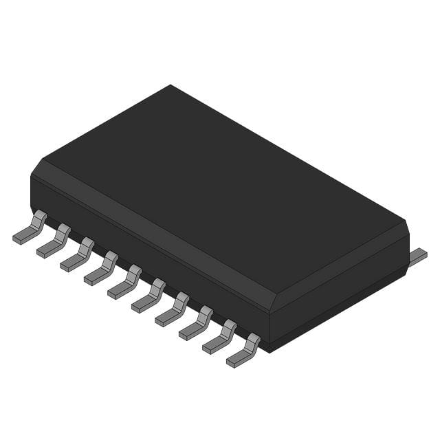
- Part No.:
- M34250E2FP
- Manufacturer:
- Renesas
- Category:
- Microcontrollers
- Package:
- -
- Datasheet:
-
 M34250E2FP.pdf
- Description:
- 4-BIT, OTPROM, MELPS720 CPU, 4.4
- Quantity:
- Payment:

- Shipping:

Inventory:11,556
Please send an inquiry. Send us your inquiry, and we will respond immediately.
Product details
Overview
M34250E2FP from Renesas Technology Corp. is a 4-bit single-chip CMOS microcomputer with mask ROM (2048 × 9 bits) and 64-word × 4-bit RAM, featuring an 8-bit timer with reload register, dual interrupt sources (external INT and Timer 1), and key-on wakeup capability on ports G, S, and INT - deployed in electric household appliances and consumer electronics such as mice.
For engineers reviewing the M34250E2FP datasheet, M34250E2FP pinout, M34250E2FP application, or M34250E2FP equivalent, this page delivers verified technical context, validated pin functions, confirmed operating voltage range (2.2 V to 5.5 V), minimum instruction execution time (1.0 µs at 4.0 MHz), and real-world I/O port behavior including N-channel open-drain structure and software-controllable pull-up/key-on wakeup functions.
Technical Context
The M34250E2FP implements the 720-series CPU core with a 4-bit ALU, 4-level hardware stack, and 1-level interrupt stack (SDP). It executes instructions at 1.0 µs minimum cycle time under 4.0 MHz system clock (VDD = 4.5–5.5 V), supported by internal CR oscillation circuit (±17% frequency error, external R/C required).
Its I/O architecture includes four independent ports: 4-bit port D (D0–D3, with D2/C and D3/K multifunction), 4-bit port S (with logic operation LGOP), 4-bit port G (G0–G3, with G0/INT and G1/TOUT), and 2-bit port F - all using N-channel open-drain outputs with programmable pull-up transistors controlled via PU0 register.
Key Specifications
| Parameter | Value and Actual Design Meaning |
|---|---|
| Core Architecture | 720-series 4-bit CPU with 4-bit ALU, 4-level subroutine stack, and 1-level interrupt stack (SDP) |
| ROM Size & Type | 2048 words × 9 bits mask ROM - fixed firmware storage, no field reprogramming |
| RAM Size | 64 words × 4 bits - supports bit-level manipulation (SB j/RB j/SZB j) and data pointer addressing |
| System Clock | CR oscillator (external R/C); ±17% accuracy at VDD = 3 V or 5 V - no crystal required |
| Supply Voltage | 2.2 V to 5.5 V (at 1.0 MHz); 4.5 V to 5.5 V (at 4.0 MHz) - enables low-power operation in battery-powered devices |
| Interrupt Sources | 2 sources: external INT (G0) and Timer 1 underflow (TOUT/G1) - vectored, priority-based (INT > Timer 1) |
| Power Consumption | 1.5 mA typical (4.0 MHz, VDD = 5 V, outputs off); 0.1 µA in RAM back-up mode - suitable for intermittent wake-up systems |
Pinout & Package
Package: 20-pin plastic molded SOP (20P2N-A), surface-mount, -20 °C to +85 °C operating temperature range.
| Pin/Terminal | Circuit Role | Design Meaning |
|---|---|---|
| VDD | Power supply | Positive supply rail (2.2–5.5 V); must be decoupled locally for noise immunity |
| VSS | Ground | 0 V reference; all unused pins should connect to VSS at shortest distance |
| CNVSS | Reset control | Must be tied to VSS to enable normal operation; "L" level initiates reset sequence |
| RESET | Reset input | Active-low asynchronous reset pin; accepts external pulse to force system restart |
| XIN / XOUT | System clock | CR oscillator interface: XIN pulled up via resistor, XOUT pulled down via capacitor |
| F0, F1 | I/O port F | 2-bit open-drain I/O; requires latch = "1" for input; no pull-up or key-on wakeup |
| G0–G3 | I/O port G | 4-bit open-drain I/O; G0 = INT input, G1 = TOUT output; all support software-configurable pull-up and key-on wakeup |
| S0–S3 | I/O port S | 4-bit open-drain I/O with logic operation (LGOP) function; key-on wakeup enabled by software |
| D0–D3 | I/O port D | 4-bit independent open-drain I/O; D2 = C, D3 = K - multifunction pins with shared latches |
| C | I/O port C | 1-bit I/O alias of D2; pull-up controllable via PU0 bit 1; used for logic operations with register A |
| K | I/O port K | 1-bit I/O alias of D3; pull-up controllable via PU0 bit 1; supports key-on wakeup |
| TOUT | Timer output | Output of Timer 1 underflow signal divided by 2; multiplexed with G1; no external load limitation specified |
| INT | Interrupt input | External interrupt trigger (level change on G0); also wakes device from RAM back-up mode |
Key Features
| Feature | Design Value |
|---|---|
| RAM back-up mode | Retains 64-word RAM contents with 0.1 µA current draw; exited via INT, TOUT, or CNVSS edge detection |
| Key-on wakeup | Configurable per-pin (ports G, S, INT) via K0 register - enables ultra-low-power human-interface wake events |
| Logic operation port | Port S supports XOR/OR/AND between register A and port S contents (via LGOP instruction and LO register) |
| Timer 1 reload capability | 8-bit timer with reload register - enables precise periodic interrupts without software reload overhead |
| Software-controllable pull-ups | Pull-up transistors on ports C, K, G0–G3, S0–S3 individually enabled/disabled via PU0 register bits |
Applications
| Mouse Controller | Remote Control Decoder |
|---|---|
Use Scenario: Low-cost optical mouse with button inputs, scroll wheel, and USB/HID interface translation. IC Role / Device Role / Timing Role: Primary MCU executing motion algorithm, debouncing buttons, managing HID report generation, and timing CR-oscillator-based polling. Use Value: 1.0 µs instruction cycle ensures responsive motion sampling; key-on wakeup on port S reduces average power during idle; 2.2 V operation extends alkaline battery life. |
Use Scenario: IR remote receiver unit decoding NEC/RC5 protocols and driving LED indicators or relay outputs. IC Role / Device Role / Timing Role: Signal acquisition via INT pin (IR carrier edge detection), protocol parsing in RAM, and output control via port D/F. Use Value: External interrupt (INT) with 2-level priority handles burst IR pulses reliably; 64-word RAM stores decoded command buffers; CR oscillator eliminates crystal BOM cost. |
| Small Appliance Timer | Smart Power Strip Logic |
Use Scenario: Programmable kitchen timer or coffee maker with push-button interface and buzzer feedback. IC Role / Device Role / Timing Role: Real-time countdown using Timer 1 reload, key scan on port S/G, buzzer drive via port F, and display segment control via port D. Use Value: Timer 1 reload register enables accurate 1-second ticks without CPU intervention; key-on wakeup on port G0–G3 allows instant resume from sleep on button press. |
Use Scenario: Multi-outlet power strip with load sensing, auto-shutoff, and manual override buttons. IC Role / Device Role / Timing Role: Monitoring zero-crossing signals (via INT), sampling current sense analog (via external ADC), and controlling triac drivers via port D outputs. Use Value: Dual interrupt sources allow concurrent handling of safety-triggered shutdown (INT) and scheduled timer events (Timer 1); 20P2N-A package fits compact PCB layouts. |
Equivalent & Alternatives
The following parts are listed as comparable options for similar 4-bit microcontroller applications.
| Alternative Part | Technical Difference | Application Difference | Selection Advice |
|---|---|---|---|
| M34250M2FP | One-Time PROM (2048 × 9 bits) instead of mask ROM; identical pinout, timing, and peripheral set | Supports firmware prototyping and small-batch customization; not suitable for high-volume cost-sensitive production | Select M34250M2FP when firmware revision flexibility is required pre-production; M34250E2FP is optimal for finalized, high-volume designs. |
| HD6417250FP | Same 4-bit 720-core architecture, 2048 × 9-bit ROM, but uses 24-pin SDIP package and lacks key-on wakeup functionality | Requires PCB redesign due to pin count and package mismatch; no built-in wake-from-sleep capability on I/O pins | Choose HD6417250FP only if legacy 24-pin layout compatibility is mandatory and key-on wakeup is unnecessary. |
Compared with M34250M2FP, M34250E2FP offers lower unit cost and higher security for mass production but forfeits field-programmability; versus HD6417250FP, it enables smaller board area and true low-power wake-on-key functionality - critical for handheld and battery-operated applications.
Availability
M34250E2FP is available at Aetrix Electronics and suitable for electric household appliances, consumer electronics mice, and small-appliance timers requiring stable component supply across long-lifecycle industrial programs.
Supply support for M34250E2FP includes scheduled delivery planning, volume procurement assistance, BOM continuity management, traceable sourcing, and lifecycle availability coordination for OEM customers, industrial embedded developers, connected-device designers, and electronics production programs.
Manufacturer
Renesas Technology Corp. was formed in 2003 through the merger of Hitachi and Mitsubishi Electric's semiconductor operations, specializing in microcontrollers, analog, and logic devices.
The M34250E2FP belongs to the 4250 Group - a family of cost-optimized 4-bit CMOS microcomputers designed for ultra-low-power, high-reliability applications in consumer and white-goods electronics.
FAQ
What is the maximum system clock frequency supported by the M34250E2FP?
The M34250E2FP supports a maximum system clock frequency of 4.0 MHz, which yields a minimum instruction execution time of 1.0 µs when VDD is 4.5 V to 5.5 V. At lower frequencies (e.g., 1.0 MHz), the device operates down to 2.2 V supply - enabling flexible power/performance trade-offs in battery-powered M34250E2FP deployments.
Does the M34250E2FP include an internal oscillator, or does it require external components?
The M34250E2FP does not include a fully integrated oscillator. It relies on an external CR oscillation circuit: XIN must be pulled up via a resistor and XOUT pulled down via a capacitor. This configuration achieves ±17% frequency accuracy over temperature and voltage - sufficient for non-critical timing in M34250E2FP applications like appliance timers and remote controls.
How many interrupt sources does the M34250E2FP support, and what are their priorities?
The M34250E2FP supports two hardware interrupt sources: external interrupt (INT pin, mapped to G0) and Timer 1 underflow (TOUT pin, mapped to G1). Priority is fixed: external interrupt (priority level 1) takes precedence over Timer 1 interrupt (priority level 2). Both use vectored addressing with dedicated entries in page 1 of ROM (0080H and 0082H).
Can the M34250E2FP retain RAM contents during power-saving mode?
Yes, the M34250E2FP supports RAM back-up mode with only 0.1 µA typical current draw at room temperature. In this mode, all 64 words × 4 bits of RAM retain data while CPU and peripherals halt. Wake-up is triggered by edge detection on INT, TOUT, or CNVSS - making M34250E2FP ideal for intermittent-operation devices like wireless remotes and portable timers.
What I/O port features distinguish the M34250E2FP from generic 4-bit microcontrollers?
The M34250E2FP provides three differentiated I/O capabilities: (1) software-selectable pull-up transistors on ports C, K, G, and S via PU0 register; (2) key-on wakeup on ports G and S plus INT pin - configurable per-pin; (3) logic operation (XOR/OR/AND) between register A and port S contents via LGOP instruction. These features directly enable low-power human-interface designs without external components in M34250E2FP implementations.
M34250E2FP Specifications
- Product attributes
- Attribute value
- Manufacturer:
- Renesas
- Package/Case:
- -
- Series:
- *
- Packaging:
- Bulk
- Product Status:
- Active
- Programmable:
- Not Verified
- Core Processor:
- -
- Core Size:
- -
- Speed:
- -
- Connectivity:
- -
- Peripherals:
- -
- Number of I/O:
- -
- Program Memory Size:
- -
- Program Memory Type:
- -
- EEPROM Size:
- -
- RAM Size:
- -
- Voltage - Supply (Vcc/Vdd):
- -
- Data Converters:
- -
- Oscillator Type:
- -
- Operating Temperature:
- -
- Grade:
- -
- Qualification:
- -
- Mounting Type:
- -
- Supplier Device Package:
M34250E2FP FAQ
1.How can I place an order for M34250E2FP through Aetrix?
Please submit a Request for Quotation (RFQ) for M34250E2FP on Aetrix. Our sales agent will provide a competitive quotation and guide you through the order confirmation once you accept the terms.
2.Are the price and stock information for M34250E2FP reliable?
The price and inventory of M34250E2FP are updated periodically and may fluctuate due to market conditions. Stock and pricing data are typically refreshed every 24 hours. Quotation validity for M34250E2FP is usually 5 days.
3.What payment methods are accepted for M34250E2FP?
We accept Wire Transfer, PayPal, Credit Card, Western Union, MoneyGram, and Escrow for M34250E2FP transactions.
Note: Certain payment methods may incur a processing fee.
4.How is shipping managed for M34250E2FP?
M34250E2FP orders can be shipped via leading logistics carriers, including DHL, UPS, FedEx, TNT, or Registered Mail.
Once your M34250E2FP order is processed, you will receive an email with the shipment details and tracking number.
Note: Tracking information may take up to 24 hours to appear. Express delivery typically takes 3–5 business days.
5.How can I obtain technical support or documentation for M34250E2FP?
For technical support, including M34250E2FP datasheets, pinout diagrams, or application guidance, please contact our engineering support team. They can provide detailed documentation and assistance for your M34250E2FP requirements.
6.How does Aetrix verify that M34250E2FP is sourced from the original manufacturer or authorized distributors?
All M34250E2FP products on Aetrix are procured from qualified distributors and authorized channels. Our dedicated quality assurance team conducts strict verification, including traceability checks and, if necessary, third-party testing. This ensures that M34250E2FP meets industry standards.
7.What is the process for return or replacement of M34250E2FP?
All M34250E2FP units undergo pre-shipment inspection (PSI). If there is an issue with M34250E2FP, returns or replacements are accepted under the following conditions:
1.Quantity discrepancies, incorrect items, or visible external defects (such as breakage or corrosion), acknowledged by Aetrix.
2.The issue is reported within 90 days of delivery.
3.The M34250E2FP part is unused and in its original packaging.
Return procedure for M34250E2FP:
1.Submit a request within 90 days.
2.Obtain a Return Material Authorization (RMA) from Aetrix.
M34250E2FP Tags

-
ATTINY4-TSHR
Microchip Technology
-
ATTINY10-TSHR
Microchip Technology
-
ATTINY10-TS8R
Microchip Technology

-
ATTINY202-SSNR
Microchip Technology
-
ATTINY202-SSFR
Microchip Technology
-
ATTINY402-SSNR
Microchip Technology

-
PIC16F15213T-I/MF
Microchip Technology
-
PIC16F15213-E/MF
Microchip Technology

-
PIC10F200T-I/OT
Microchip Technology
-
ATTINY412-SSNR
Microchip Technology
-
PIC10F202T-I/OT
Microchip Technology

-
ATTINY404-SSNR
Microchip Technology
Tech Hub

A practical engineering and sourcing framework covering lifecycle verification, lifetime-buy calculations, replacement qualification, supplier checks and counterfeit-risk controls.

TTL and CMOS logic families differ in thresholds, loading, output drive, power and timing. This engineering guide compares 74HC and 74HCT, calculates noise margins and checks 3.3 V/5 V compatibility.

A practical engineering guide to 3.3V and 5V logic compatibility, input thresholds, resistor dividers, translator ICs, MOSFET level shifting, I2C pull-ups, timing limits and power-sequencing risks.

The 74HC595 uses push-pull logic outputs, while the TPIC6B595 uses 50 V open-drain DMOS sinks for higher-power loads. This guide compares timing, current limits, 3.3 V interfacing, load wiring, thermal…

The 74HC595 converts serial data into eight stable parallel outputs. This guide covers pin functions, shift and storage timing, OE and MR behavior, drive-current limits, cascading, voltage compatibilit…

A technical comparison of level-sensitive latches and edge-triggered flip-flops, covering timing windows, setup and hold limits, master–slave operation, time borrowing, race-through, HDL inference and…

A D latch stores one bit while Enable controls when data can pass. This reference covers gate-level operation, truth tables, transparency, setup and hold timing, LE versus OE, common ICs and practical …

An SR latch stores one bit through cross-coupled feedback. This engineering reference covers NOR and NAND implementations, truth tables, forbidden-state recovery, gated operation, switch debouncing, fa…

Latch circuits retain one bit through feedback. This technical reference covers SR and D latches, truth tables, transparency, timing limits, latch-versus-flip-flop behavior, applications and common log…

An engineering guide to LED driver operation, constant-current and constant-voltage outputs, linear and switching topologies, dimming, IC selection, calculations, replacement compatibility, and fault c…


