
 My Inquiry
 My Account


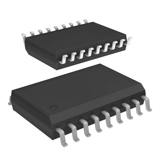
STMicroelectronics M41T83SMY6F
- Part No.:
- M41T83SMY6F
- Manufacturer:
- STMicroelectronics
- Category:
- Real Time Clocks
- Package:
- 18-SOX, 18-SOIC with Crystal (7.5mm Width)
- Datasheet:
-
 M41T83SMY6F.pdf
- Description:
- IC RTC CLK/CALENDAR I2C 18SOX
- Quantity:
- Payment:

- Shipping:

Inventory:1,355
Please send an inquiry. Send us your inquiry, and we will respond immediately.
Product details
Overview
M41T83SMY6F from STMicroelectronics is a serial I²C real-time clock (RTC) with embedded 32.768 kHz crystal in SOX18 package, providing battery-backed timekeeping, dual alarms, watchdog timer, 8-bit counter/timer, and 7-byte SRAM. It operates from 2.38 V to 5.50 V, achieves ±5 ppm factory-calibrated accuracy after two reflows, and consumes only 365 nA in battery backup mode. Used in industrial control panels requiring long-term timestamping during mains loss.
For engineers reviewing the M41T83SMY6F datasheet, M41T83SMY6F pinout, M41T83SMY6F application, or M41T83SMY6F equivalent, key selection criteria include embedded crystal integration, ultra-low backup current, programmable analog/digital calibration, and dual-alarm interrupt capability under VBAT operation.
Technical Context
The M41T83SMY6F implements a fully autonomous RTC subsystem with integrated oscillator circuitry - the SOX18 package embeds a precision 32.768 kHz crystal, eliminating external load capacitor requirements and layout sensitivity. Its I²C interface supports 400 kHz protocol with automatic address incrementing across 32 registers.
It features dual independent alarm comparators (A1IE/A2IE), a watchdog timer with configurable timeout, and a programmable 8-bit countdown timer with interrupt enable (TIE). The device includes oscillator fail detection, battery low flag, and power-on reset (RST) output with fixed 2.93 V switchover threshold for the 'S' variant.
Key Specifications
| Parameter | Value and Actual Design Meaning |
|---|---|
| Backup Current | 365 nA - enables >10-year coin-cell battery life in backup mode |
| Accuracy | ±5 ppm typical after 2 reflows - stable timekeeping without post-assembly recalibration |
| Operating Voltage | 2.38 V to 5.50 V - supports wide-input industrial power rails and brownout resilience |
| I²C Speed | 400 kHz - compatible with standard fast-mode microcontroller peripherals |
| SRAM Size | 7 bytes battery-backed - retains critical state or calibration data during power loss |
| Alarm Count | 2 programmable alarms - enables dual-event scheduling (e.g., wake + log) |
| Timer Resolution | 244.1 µs to 4.25 hrs - selectable via 4-bit prescaler for flexible timing intervals |
| Temp Range | –40 °C to +85 °C - qualified for extended industrial ambient conditions |
Pinout & Package
Package: SOX18 (18-lead plastic small outline, 300 mil, embedded crystal, 11.61 mm × 7.62 mm).
| Pin/Terminal | Circuit Role | Design Meaning |
|---|---|---|
| 1, 2, 3, 16, 17, 18 | NF (No Connect) | Internally unused; must be tied to VSS per datasheet |
| 4 | SQW | Programmable square wave output; defaults to 32 kHz on power-up |
| 5 | NC | No internal connection; left floating or grounded |
| 6 | RST | Open-drain power-on reset output; active-low, 2.93 V threshold |
| 7 | IRQ2 | Open-drain interrupt output for Alarm 2 |
| 8 | SCL | I²C clock input; requires pull-up to VCC |
| 9 | SDA | I²C bidirectional data line; requires pull-up to VCC |
| 10 | VSS | Digital ground reference |
| 11 | VBAT | Battery supply input; powers RTC during main power loss |
| 12 | VCC | Main supply voltage (2.38–5.50 V) |
| 13 | IRQ1/FT/OUT | Open-drain multifunction pin: Alarm 1 interrupt, frequency test, or general-purpose output |
| 14, 15 | NC | No internal connection; left floating or grounded |
Key Features
| Feature | Design Value |
|---|---|
| Embedded Crystal | SOX18 package integrates factory-trimmed 32.768 kHz crystal - eliminates external component count and layout tuning |
| Dual Alarm System | Two independent BCD-compare alarms with separate interrupt outputs (IRQ1/IRQ2) - enables concurrent event triggers |
| Calibration Flexibility | Combined analog (load capacitance adjustment) and digital (periodic counter correction) calibration - supports field accuracy optimization |
| Power Switchover Logic | Fixed 2.93 V VSO threshold with automatic VBAT takeover - ensures seamless timekeeping during brownout |
| Oscillator Fail Detection | Dedicated circuit monitors crystal oscillation and asserts flag/interrupt - prevents silent time drift failure |
| OTP Memory | 8 bits of one-time-programmable memory - stores unique device identifiers or calibration offsets |
Applications
| Industrial Data Logger | Smart Energy Meter |
|---|---|
Use Scenario: Records sensor readings with precise timestamps during grid outages using coin-cell backup. IC Role / Device Role / Timing Role: Primary RTC with battery-switchover and oscillator fail detection ensures timestamp integrity. Use Value: 365 nA backup current extends 12-month CR2032 life beyond 10 years; embedded crystal avoids aging-induced drift. | Use Scenario: Maintains billing calendar and tariff schedule across daily power cycles and seasonal firmware updates. IC Role / Device Role / Timing Role: Time-of-day/calendar engine with century-bit support and leap-year correction. Use Value: ±5 ppm accuracy minimizes cumulative error to <1.6 seconds/month; dual alarms trigger tariff switches and diagnostics. |
| Medical Infusion Pump | Railway Signaling Controller |
Use Scenario: Tracks therapy duration and logs dose events with audit-trail timestamps compliant with IEC 62304. IC Role / Device Role / Timing Role: Safety-critical timekeeper with watchdog timer and battery-low warning. Use Value: Watchdog timeout resets MCU on firmware hang; RST output synchronizes system reset with clock domain. | Use Scenario: Synchronizes interlocking logic and event logging across distributed trackside cabinets operating at –40 °C. IC Role / Device Role / Timing Role: Industrial-grade RTC with extended temperature qualification and ESD-hardened I²C pins. Use Value: –40 °C to +85 °C operation ensures reliability in unheated enclosures; open-drain IRQ pins interface directly with 24 V PLC inputs. |
Equivalent & Alternatives
The following parts are listed as comparable options for similar real-time clock applications.
| Alternative Part | Technical Difference | Application Difference | Selection Advice |
|---|---|---|---|
| DS3231SN#T&R | ±2 ppm accuracy, integrated TCXO, higher 1.3 µA backup current | Higher precision required; less sensitive to temperature variation | Select for sub-second monthly drift; avoid if coin-cell lifetime >10 years is mandatory |
| PCF8563T/2,118 | 300 nA backup current, no embedded crystal, ±20 ppm accuracy | Cost-sensitive designs accepting lower accuracy; external crystal layout acceptable | Select when BOM cost reduction outweighs crystal placement complexity and calibration effort |
Compared with DS3231SN#T&R, M41T83SMY6F trades absolute accuracy for ultra-low power and embedded simplicity; versus PCF8563T/2,118, it delivers superior stability and eliminates crystal matching risk at modest cost premium.
Availability
M41T83SMY6F is available at Aetrix Electronics and suitable for industrial data loggers, smart energy meters, medical infusion pumps, and railway signaling controllers requiring stable component supply across extended product lifecycles.
Supply support for M41T83SMY6F includes scheduled delivery planning, volume procurement assistance, BOM continuity management, traceable sourcing, and lifecycle availability coordination for OEM customers, industrial embedded developers, connected-device designers, and electronics production programs.
Manufacturer
STMicroelectronics is a global semiconductor leader headquartered in Geneva, designing and manufacturing microcontrollers, power ICs, sensors, and timing solutions for industrial, automotive, and consumer markets.
The M41T8x series targets industrial and infrastructure applications demanding high reliability, long-term timekeeping autonomy, and minimal external component count - especially where embedded crystal integration reduces design risk.
FAQ
What is the function of the DU pin on M41T83SMY6F?
The DU (Don't Use) pin (Pin 3) must be tied to VCC and has no internal function. Leaving it unconnected violates the SOX18 package specification and may cause undefined behavior during power transitions. This requirement is explicitly stated in the datasheet's pin description table and hardware hookup diagrams.
Does M41T83SMY6F support I²C clock stretching?
Yes - the M41T83SMY6F supports I²C clock stretching during register read/write operations. When internal processing (e.g., BCD-to-binary conversion or alarm comparison) is ongoing, the device holds SCL low until ready, ensuring data coherency without host-side timing assumptions.
How is the century bit implemented in the M41T83SMY6F calendar?
The M41T83SMY6F uses two dedicated bits (CB1:CB0) in the century register to encode years 2000–2099 (00), 2100–2199 (01), 2200–2299 (10), and 2300–2399 (11). These bits auto-advance with year rollover and are accessible via register address 0x04, enabling unambiguous Y2K+ compliance without software workarounds.
Can the SQW output be disabled or repurposed?
Yes - the SQW output is controlled by the SQWE (Square Wave Enable) bit in the control register (address 0x0E). Clearing SQWE disables the output driver, placing SQW in high-impedance state. It cannot be reassigned to other functions; its sole purpose is 32.768 kHz or divided-frequency waveform generation.
M41T83SMY6F Specifications
- Product attributes
- Attribute value
- Manufacturer:
- STMicroelectronics
- Series:
- -
- Package/Case:
- 18-SOX, 18-SOIC with Crystal (7.5mm Width)
- Packaging:
- Tape & Reel (TR)
- Product Status:
- Active
- Programmable:
- Not Verified
- Type:
- Clock/Calendar
- Features:
- Alarm, Leap Year, Square Wave Output, SRAM, Watchdog Timer
- Memory Size:
- 7B
- Time Format:
- HH:MM:SS:hh (24 hr)
- Date Format:
- YY-MM-DD-dd
- Interface:
- I2C, 2-Wire Serial
- Voltage - Supply:
- 3V ~ 5.5V
- Voltage - Supply, Battery:
- 2V ~ 5.5V
- Current - Timekeeping (Max):
- 10µA @ 5.5V
- Operating Temperature:
- -40°C ~ 85°C
- Mounting Type:
- Surface Mount
- Grade:
- -
- Qualification:
- -
- Supplier Device Package:
- 18-SOX
M41T83SMY6F FAQ
1.How can I place an order for M41T83SMY6F through Aetrix?
Please submit a Request for Quotation (RFQ) for M41T83SMY6F on Aetrix. Our sales agent will provide a competitive quotation and guide you through the order confirmation once you accept the terms.
2.Are the price and stock information for M41T83SMY6F reliable?
The price and inventory of M41T83SMY6F are updated periodically and may fluctuate due to market conditions. Stock and pricing data are typically refreshed every 24 hours. Quotation validity for M41T83SMY6F is usually 5 days.
3.What payment methods are accepted for M41T83SMY6F?
We accept Wire Transfer, PayPal, Credit Card, Western Union, MoneyGram, and Escrow for M41T83SMY6F transactions.
Note: Certain payment methods may incur a processing fee.
4.How is shipping managed for M41T83SMY6F?
M41T83SMY6F orders can be shipped via leading logistics carriers, including DHL, UPS, FedEx, TNT, or Registered Mail.
Once your M41T83SMY6F order is processed, you will receive an email with the shipment details and tracking number.
Note: Tracking information may take up to 24 hours to appear. Express delivery typically takes 3–5 business days.
5.How can I obtain technical support or documentation for M41T83SMY6F?
For technical support, including M41T83SMY6F datasheets, pinout diagrams, or application guidance, please contact our engineering support team. They can provide detailed documentation and assistance for your M41T83SMY6F requirements.
6.How does Aetrix verify that M41T83SMY6F is sourced from the original manufacturer or authorized distributors?
All M41T83SMY6F products on Aetrix are procured from qualified distributors and authorized channels. Our dedicated quality assurance team conducts strict verification, including traceability checks and, if necessary, third-party testing. This ensures that M41T83SMY6F meets industry standards.
7.What is the process for return or replacement of M41T83SMY6F?
All M41T83SMY6F units undergo pre-shipment inspection (PSI). If there is an issue with M41T83SMY6F, returns or replacements are accepted under the following conditions:
1.Quantity discrepancies, incorrect items, or visible external defects (such as breakage or corrosion), acknowledged by Aetrix.
2.The issue is reported within 90 days of delivery.
3.The M41T83SMY6F part is unused and in its original packaging.
Return procedure for M41T83SMY6F:
1.Submit a request within 90 days.
2.Obtain a Return Material Authorization (RMA) from Aetrix.
M41T83SMY6F Tags

-
MCP7940N-I/SN
Microchip Technology

-
MCP7940MT-I/MNY
Microchip Technology

-
PCF85063ATL/1,118
NXP USA Inc.
-
MCP7940NT-I/SN
Microchip Technology

-
MCP7940NT-I/MS
Microchip Technology
-
MCP7940N-I/MS
Microchip Technology

-
PCF85063AT/AY
NXP USA Inc.

-
PCF85063TP/1Z
NXP Semiconductors

-
PCF85063ATT/AJ
NXP USA Inc.
-
MCP7940NT-E/SN
Microchip Technology
-
MCP7940NT-I/MNY
Microchip Technology
-
MCP79400T-I/SN
Microchip Technology
Tech Hub

A practical engineering and sourcing framework covering lifecycle verification, lifetime-buy calculations, replacement qualification, supplier checks and counterfeit-risk controls.

TTL and CMOS logic families differ in thresholds, loading, output drive, power and timing. This engineering guide compares 74HC and 74HCT, calculates noise margins and checks 3.3 V/5 V compatibility.

A practical engineering guide to 3.3V and 5V logic compatibility, input thresholds, resistor dividers, translator ICs, MOSFET level shifting, I2C pull-ups, timing limits and power-sequencing risks.

The 74HC595 uses push-pull logic outputs, while the TPIC6B595 uses 50 V open-drain DMOS sinks for higher-power loads. This guide compares timing, current limits, 3.3 V interfacing, load wiring, thermal…

The 74HC595 converts serial data into eight stable parallel outputs. This guide covers pin functions, shift and storage timing, OE and MR behavior, drive-current limits, cascading, voltage compatibilit…

A technical comparison of level-sensitive latches and edge-triggered flip-flops, covering timing windows, setup and hold limits, master–slave operation, time borrowing, race-through, HDL inference and…

A D latch stores one bit while Enable controls when data can pass. This reference covers gate-level operation, truth tables, transparency, setup and hold timing, LE versus OE, common ICs and practical …

An SR latch stores one bit through cross-coupled feedback. This engineering reference covers NOR and NAND implementations, truth tables, forbidden-state recovery, gated operation, switch debouncing, fa…

Latch circuits retain one bit through feedback. This technical reference covers SR and D latches, truth tables, transparency, timing limits, latch-versus-flip-flop behavior, applications and common log…

An engineering guide to LED driver operation, constant-current and constant-voltage outputs, linear and switching topologies, dimming, IC selection, calculations, replacement compatibility, and fault c…


