
 My Inquiry
 My Account


STMicroelectronics M48T02-150PC1
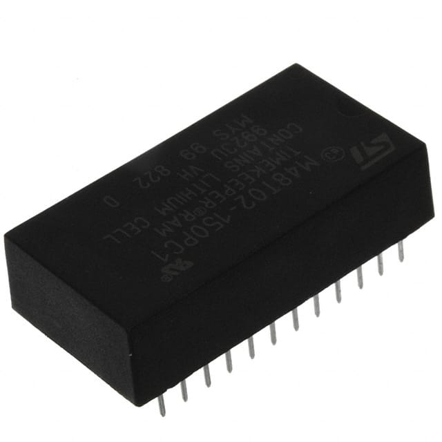
- Part No.:
- M48T02-150PC1
- Manufacturer:
- STMicroelectronics
- Category:
- Real Time Clocks
- Package:
- 24-DIP Module (0.600", 15.24mm)
- Datasheet:
-
 M48T02-150PC1.pdf
- Description:
- IC RTC CLK/CALENDAR PAR 24DIP
- Quantity:
- Payment:

- Shipping:

Inventory:127
Please send an inquiry. Send us your inquiry, and we will respond immediately.
Product details
Overview
M48T02-150PC1 from STMicroelectronics is a 5.0 V, 16 Kbit (2 Kb × 8) non-volatile TIMEKEEPER® SRAM integrating ultra-low-power static RAM, real-time clock, and power-fail control circuitry in a single CAPHAT™ DIP package. It features BCD-coded timekeeping registers (year/month/day/hour/minute/second), ±1 minute/month typical clock accuracy at 25 °C, software-controlled calibration, automatic WRITE protection during VCC brownout, and self-contained lithium battery + 32.768 kHz crystal. Used in industrial control panels for timestamped event logging under intermittent power.
For engineers reviewing the M48T02-150PC1 datasheet, M48T02-150PC1 pinout, M48T02-150PC1 application, or M48T02-150PC1 equivalent, key selection criteria include battery-backed RTC retention duration, BYTEWIDE™ SRAM compatibility with JEDEC 2K×8 sockets, VPFD voltage window (4.5–4.75 V), BOK flag behavior on power-up, and calibration register resolution (±5.35 s/month per LSB).
Technical Context
The M48T02-150PC1 integrates a BiPORT™ SRAM array and quartz oscillator on one die, with clock data mapped to memory-mapped registers at addresses 7F8h–7FFh. The clock control register (7F8h) includes READ/WRITE/STOP/FT bits and a 5-bit calibration field with sign bit, enabling ±31-step adjustment of oscillator timing via pulse blanking/splitting at the ÷256 stage.
Power management uses dual-threshold detection: VPFD (4.5–4.75 V) triggers write-protection and high-Z outputs; VSO (~3 V) initiates battery switchover. The BOK flag indicates low battery voltage post-power-up and blocks first WRITE until cleared by successful write operation - ensuring data integrity during backup power transition.
Key Specifications
| Parameter | Value and Actual Design Meaning |
|---|---|
| Memory size | 2 Kb × 8 = 16 Kbit SRAM with non-volatile retention via integrated Li battery |
| Supply voltage | VCC = 4.75–5.5 V; ensures compatibility with standard 5 V logic systems |
| VPFD range | 4.5 V ≤ VPFD ≤ 4.75 V; defines precise voltage window for automatic WRITE protect activation |
| Timing accuracy | ±1 minute/month at 25 °C; enables long-term timestamp reliability without external calibration |
| Access time | 150 ns max (–150 suffix); guarantees deterministic read/write latency for real-time embedded firmware |
| Crystal frequency | 32.768 kHz; standard low-power RTC reference enabling accurate second counting |
| Calibration resolution | ±5.35 s/month per LSB; allows fine-grained software tuning of clock drift across temperature |
Pinout & Package
Package: PCDIP24 - 24-pin plastic DIP with integrated CAPHAT™ battery and crystal.
| Pin/Terminal | Circuit Role | Design Meaning |
|---|---|---|
| A0–A10 | Address inputs | 11-bit address bus for accessing 2,048 bytes of SRAM and TIMEKEEPER registers (7F8h–7FFh) |
| DQ0–DQ7 | Data I/O | 8-bit bidirectional data bus supporting BYTEWIDE™ clock register reads/writes like standard SRAM |
| E | Chip enable | Active-low signal enabling memory access; controls power-fail detection sampling when asserted |
| G | Output enable | Active-low three-state control for DQ lines; must be high during WRITE to avoid bus contention |
| W | WRITE enable | Active-low signal initiating WRITE cycles; falling edge synchronizes data latch timing |
| VCC | Supply voltage | Primary 5 V supply; powers SRAM and clock circuitry; monitored for VPFD/VSO thresholds |
| VSS | Ground | Reference return path for all digital and analog functions including oscillator bias |
Key Features
| Feature | Design Value |
|---|---|
| Self-contained CAPHAT™ package | Integrates Li battery + 32.768 kHz crystal + IC in single PCDIP24 footprint - eliminates external component sourcing and layout complexity |
| Memory-mapped RTC registers | Time/date stored in BCD format at fixed SRAM addresses (7F8h–7FFh), accessible using standard READ/WRITE instructions without custom I²C/SPI drivers |
| Automatic power-fail protection | Hardware-level WRITE disable and output high-Z activation within VPFD window - prevents corruption during brownout without firmware intervention |
| Software-calibratable oscillator | 5-bit signed calibration register adjusts timing in ±5.35 s/month steps via internal pulse manipulation - enables field calibration without hardware modification |
| BOK flag monitoring | Read-once battery health indicator set on power-up if battery voltage falls below threshold - blocks first WRITE until validated, preventing silent data loss |
Applications
| Industrial PLC Event Logger | Medical Device Power-Fail Timestamping |
|---|---|
|
Use Scenario: Programmable logic controller logs machine fault events with precise timestamps during factory floor power fluctuations. IC Role / Device Role / Timing Role: Non-volatile SRAM stores log entries; RTC provides BCD-formatted wall-clock time synchronized to system reset. Use Value: Maintains accurate time and log integrity for ≥10 years on integrated battery - eliminates need for external RTC + EEPROM co-design and reduces BOM count by 2 components. |
Use Scenario: Infusion pump records therapy start/stop times and error codes when AC power fails mid-treatment. IC Role / Device Role / Timing Role: Acts as sole time source and data buffer; VPFD-triggered WRITE protect prevents log overwrite during brownout. Use Value: Guarantees audit-trail compliance under IEC 62304; BOK flag alerts firmware to replace battery before clinical use degradation occurs. |
| Point-of-Sale Transaction Recorder | Smart Meter Firmware Update Log |
|
Use Scenario: Cash register writes sales transaction timestamps to local memory before uploading to cloud; must survive brief grid outages. IC Role / Device Role / Timing Role: Provides atomic timestamp+data storage using same address/data bus - no arbitration logic required. Use Value: Enables JEDEC SRAM socket drop-in replacement; eliminates need for separate RTC interrupt line and reduces PCB layer count by consolidating timing + memory. |
Use Scenario: Electricity meter logs firmware update attempts and success/failure status with verifiable UTC-aligned timestamps. IC Role / Device Role / Timing Role: Stores update metadata in SRAM while RTC maintains traceable time base across power cycles. Use Value: Supports DLMS/COSEM compliance via battery-backed time continuity; calibration register allows utility-grade ±15 s/year accuracy after field tuning. |
Equivalent & Alternatives
The following parts are listed as comparable options for similar battery-backed RTC+SRAM applications.
| Alternative Part | Technical Difference | Application Difference | Selection Advice |
|---|---|---|---|
| DS1642-150+ (Maxim Integrated) | Same pin/function compatibility; requires external crystal and battery; no integrated CAPHAT™ package | Lacks self-contained power solution - demands additional board space, layout care for crystal load caps, and battery holder integration | Select only if legacy DS1642 footprint reuse is mandatory and CAPHAT™ mechanical constraints are unacceptable |
| M48T35Y-150PC1 (STMicroelectronics) | Higher density (64 Kbit SRAM); identical RTC architecture and CAPHAT™ packaging; wider VCC range (4.5–5.5 V) | Supports larger log buffers but increases cost and power draw - unnecessary for sub-2KB timestamping requirements | Choose when future firmware expansion requires >2 KB non-volatile storage without changing board layout or power design |
Compared with DS1642-150+, M48T02-150PC1 reduces bill-of-materials and assembly risk via integrated battery/crystal; versus M48T35Y-150PC1, it delivers optimal cost-performance balance for applications needing only 2 KB of timestamped storage.
Availability
M48T02-150PC1 is available at Aetrix Electronics and suitable for industrial control panels, medical infusion pumps, point-of-sale terminals, and smart electricity meters requiring stable component supply with guaranteed 10-year battery retention and RoHS-compliant lead-free interconnects.
Supply support for M48T02-150PC1 includes scheduled delivery planning, volume procurement assistance, BOM continuity management, traceable sourcing, and lifecycle availability coordination for OEM customers, industrial embedded developers, connected-device designers, and electronics production programs.
Manufacturer
STMicroelectronics is a global semiconductor leader headquartered in Geneva, Switzerland, designing and manufacturing microcontrollers, power management ICs, sensors, and analog/mixed-signal devices for automotive, industrial, and consumer markets.
The TIMEKEEPER® product line targets embedded systems requiring autonomous, long-life timekeeping with zero external components - specifically engineered for industrial automation, medical instrumentation, and energy metering where timestamp integrity is safety- or compliance-critical.
FAQ
What is the guaranteed data retention period for M48T02-150PC1 under continuous battery backup?
The M48T02-150PC1 guarantees ≥10 years of data and clock retention in battery-backup mode across the full operating temperature range (0–70 °C), based on integrated lithium button cell capacity and low-quiescent-current oscillator design. This value is measured under worst-case conditions and does not require periodic refresh or external power cycling.
How does the BOK (Battery OK) flag function during power-up sequences?
On power-up, the M48T02-150PC1 samples battery voltage and sets the BOK flag if it falls below the threshold. When set, the first attempted WRITE operation is blocked until the write succeeds, at which point the flag clears automatically. This prevents corrupted timestamps or log entries due to insufficient backup power during critical initialization.
Can the M48T02-150PC1 be used as a direct replacement for standard 2K×8 SRAMs without modifying existing firmware?
Yes - the M48T02-150PC1 is pin- and function-compatible with JEDEC-standard 2K×8 SRAMs. Standard READ/WRITE cycles access SRAM locations 000h–7F7h identically; TIMEKEEPER registers reside at 7F8h–7FFh and require no special timing, enabling drop-in replacement in most legacy designs with minimal firmware updates.
What is the purpose and behavior of the STOP bit in the seconds register (7F9h)?
The STOP bit (MSB of 7F9h) halts the 32.768 kHz oscillator to conserve battery during extended shelf life or storage. The device ships with STOP=1. Writing STOP=0 resumes oscillation within one second. While stopped, RTC registers retain last valid time but do not advance - preserving timestamp consistency across power-off periods.
M48T02-150PC1 Specifications
- Product attributes
- Attribute value
- Manufacturer:
- STMicroelectronics
- Series:
- Timekeeper®
- Package/Case:
- 24-DIP Module (0.600", 15.24mm)
- Packaging:
- Tube
- Product Status:
- Active
- Programmable:
- Not Verified
- Type:
- Clock/Calendar
- Features:
- Leap Year
- Memory Size:
- -
- Time Format:
- HH:MM:SS (24 hr)
- Date Format:
- YY-MM-DD-dd
- Interface:
- Parallel
- Voltage - Supply:
- 4.75V ~ 5.5V
- Voltage - Supply, Battery:
- -
- Current - Timekeeping (Max):
- 3mA @ 4.7V ~ 5.5V
- Operating Temperature:
- 0°C ~ 70°C
- Mounting Type:
- Through Hole
- Grade:
- -
- Qualification:
- -
- Supplier Device Package:
- 24-PCDIP, CAPHAT®
M48T02-150PC1 FAQ
1.How can I place an order for M48T02-150PC1 through Aetrix?
Please submit a Request for Quotation (RFQ) for M48T02-150PC1 on Aetrix. Our sales agent will provide a competitive quotation and guide you through the order confirmation once you accept the terms.
2.Are the price and stock information for M48T02-150PC1 reliable?
The price and inventory of M48T02-150PC1 are updated periodically and may fluctuate due to market conditions. Stock and pricing data are typically refreshed every 24 hours. Quotation validity for M48T02-150PC1 is usually 5 days.
3.What payment methods are accepted for M48T02-150PC1?
We accept Wire Transfer, PayPal, Credit Card, Western Union, MoneyGram, and Escrow for M48T02-150PC1 transactions.
Note: Certain payment methods may incur a processing fee.
4.How is shipping managed for M48T02-150PC1?
M48T02-150PC1 orders can be shipped via leading logistics carriers, including DHL, UPS, FedEx, TNT, or Registered Mail.
Once your M48T02-150PC1 order is processed, you will receive an email with the shipment details and tracking number.
Note: Tracking information may take up to 24 hours to appear. Express delivery typically takes 3–5 business days.
5.How can I obtain technical support or documentation for M48T02-150PC1?
For technical support, including M48T02-150PC1 datasheets, pinout diagrams, or application guidance, please contact our engineering support team. They can provide detailed documentation and assistance for your M48T02-150PC1 requirements.
6.How does Aetrix verify that M48T02-150PC1 is sourced from the original manufacturer or authorized distributors?
All M48T02-150PC1 products on Aetrix are procured from qualified distributors and authorized channels. Our dedicated quality assurance team conducts strict verification, including traceability checks and, if necessary, third-party testing. This ensures that M48T02-150PC1 meets industry standards.
7.What is the process for return or replacement of M48T02-150PC1?
All M48T02-150PC1 units undergo pre-shipment inspection (PSI). If there is an issue with M48T02-150PC1, returns or replacements are accepted under the following conditions:
1.Quantity discrepancies, incorrect items, or visible external defects (such as breakage or corrosion), acknowledged by Aetrix.
2.The issue is reported within 90 days of delivery.
3.The M48T02-150PC1 part is unused and in its original packaging.
Return procedure for M48T02-150PC1:
1.Submit a request within 90 days.
2.Obtain a Return Material Authorization (RMA) from Aetrix.
M48T02-150PC1 Tags

-
MCP7940N-I/SN
Microchip Technology

-
MCP7940MT-I/MNY
Microchip Technology

-
PCF85063ATL/1,118
NXP USA Inc.
-
MCP7940NT-I/SN
Microchip Technology

-
MCP7940NT-I/MS
Microchip Technology
-
MCP7940N-I/MS
Microchip Technology

-
PCF85063AT/AY
NXP USA Inc.

-
PCF85063TP/1Z
NXP USA Inc.

-
PCF85063ATT/AJ
NXP USA Inc.
-
MCP7940NT-E/SN
Microchip Technology
-
MCP7940NT-I/MNY
Microchip Technology
-
MCP79400T-I/SN
Microchip Technology
Tech Hub

Jumper cables guide covering safe connection order, red and black clamp placement, final ground connection, cable gauge, length, clamp quality, copper vs CCA cables, jump starter comparison and battery…

LDO regulator guide covering low dropout voltage, power dissipation, thermal design, PSRR, output noise, capacitor stability, adjustable LDO circuits, LDO vs buck converter and datasheet selection chec…

Conditional Access Module guide covering CAM meaning, CI/CI+ interface, smart card authorization, DVB security workflow, TV and set-top box compatibility, internal electronics, ESD protection, connecto…

Guide to electronic component obsolescence covering EOL risk, PCN/PDN notices, last-time buy planning, replacement options, form-fit-function validation, counterfeit risk and BOM lifecycle management.

18650 battery guide covering lithium-ion cell basics, 3.6V/3.7V voltage, 4.2V charging, mAh and Wh capacity, protected cells, chargers, BMS, series-parallel packs, holders, welding and sourcing checks.…

Hall effect sensor guide covering working principle, linear and digital sensors, Arduino circuits, current sensing, speed detection, automotive applications, A3144 examples, signal filtering and datash…

Product Change Notification guide for electronic components, covering PCN meaning, PCN vs PDN/EOL, common change types, risk levels, form-fit-function review, engineering validation, BOM control, LTB/L…

A practical guide to blend door actuators, covering HVAC function, symptoms, location, AC and heater issues, reset and calibration, replacement cost, electrical diagnosis, compatibility checks, and rep…

Engineering guide to Raspberry Pi alternatives, covering chip-level differences, Orange Pi, ROCK, Jetson, Banana Pi, NanoPi, Compute Module, Pico, GPIO, camera, HAT compatibility, and replacement risks…

Engineering guide to dynamic load response testing for high-current buck converters, covering load step setup, slew rate, Vcore undershoot, overshoot, recovery time, probe location, output capacitors a…


