
 My Inquiry
 My Account


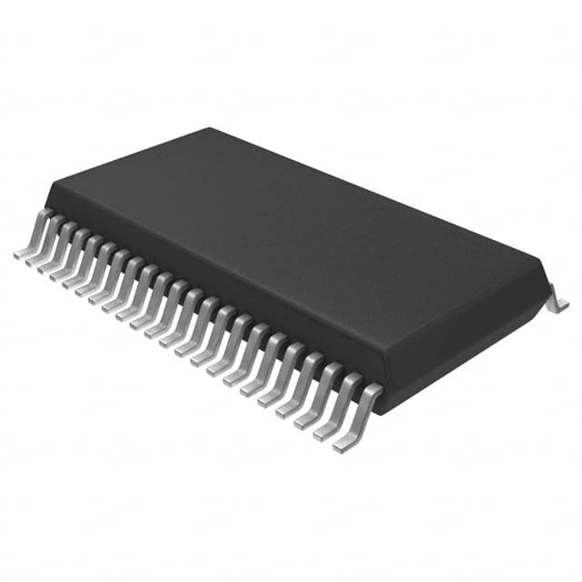
STMicroelectronics M48T201V-85MH1F
- Part No.:
- M48T201V-85MH1F
- Manufacturer:
- STMicroelectronics
- Category:
- Real Time Clocks
- Package:
- 44-BSOP (0.337", 8.56mm Width) requires SNAPHAT
- Datasheet:
-
 M48T201V-85MH1F.pdf
- Description:
- IC RTC CLK/CALENDAR PAR 44SOH
- Quantity:
- Payment:

- Shipping:

Inventory:621
Please send an inquiry. Send us your inquiry, and we will respond immediately.
Product details
Overview
M48T201V-85MH1F from STMicroelectronics is a 3.3 V TIMEKEEPER® supervisor IC integrating real-time clock (RTC), watchdog timer, programmable alarm, power-fail detection, and SRAM interface control. It converts external low-power SRAM into nonvolatile memory (NVRAM) via battery-backed operation, supports up to 512 K × 8 SRAM, and provides year-2000-compliant timekeeping with automatic leap-year correction through 2100. Used in industrial control panels for timestamped event logging during mains failure.
For engineers reviewing the M48T201V-85MH1F datasheet, M48T201V-85MH1F pinout, M48T201V-85MH1F application, or M48T201V-85MH1F equivalent, key selection criteria include VCC range (3.0–3.6 V), VPFD threshold (2.7–3.0 V), tAVAV timing (85 ns), SNAPHAT®-compatible SOIC-44 packaging, and integrated RTC register map (7FFF0h–7FFFFh).
Technical Context
The device implements a dual-mode memory controller: GCON/ECON signals selectively enable external SRAM or internal TIMEKEEPER® registers based on address decoding (A0–A18), with transparent memory mapping across 7FFF0h–7FFFFh. Its power-fail circuitry monitors VCC against VPFD and triggers automatic write protection and battery switchover at VSO.
RTC functionality resides in nine dedicated BiPORT™ RAM locations updated once per second; alarm and watchdog functions are configured via registers 7FFF2h–7FFF7h, with interrupt/reset output via IRQ/FT and RST pins. Square wave output frequency is programmable (32.768 kHz, 1 kHz, 64 Hz, 1 Hz) using RS0–RS3 bits in register 7FFF0h.
Key Specifications
| Parameter | Value and Actual Design Meaning |
|---|---|
| VCC Range | 3.0 V to 3.6 V - defines compatible host system supply rail; enables direct interface with 3.3 V microcontrollers without level shifting. |
| VPFD Threshold | 2.7 V ≤ VPFD ≤ 3.0 V - sets precise voltage window for power-fail detection and automatic SRAM write protection activation. |
| tAVAV (Read/Write) | 85 ns - maximum access cycle time; ensures compatibility with standard 3.3 V low-power SRAMs operating at ≤12 MHz. |
| RTC Accuracy | ±20 ppm over 0 °C to +70 °C - translates to ±1.7 sec/day drift; sufficient for industrial timestamping without external calibration. |
| Battery Switchover (VSO) | Typ. 2.5 V - triggers seamless transition from VCC to SNAPHAT® lithium cell, preserving RTC and SRAM data during brownout. |
| Square Wave Output | Programmable (32.768 kHz / 1 kHz / 64 Hz / 1 Hz) - provides configurable clock source for MCU wake-up or peripheral synchronization. |
| Alarm Function | Month/date/hour/minute/second match - enables precise scheduled interrupts (e.g., daily log rollover or maintenance alerts) in battery-backup mode. |
Pinout & Package
44-pin SOIC (SOH44, 330 mil width) with gold-plated edge contacts for direct top-mounting of SNAPHAT® battery/crystal housing (e.g., M4Txx-BR12SH). Package supports surface-mount reflow before SNAPHAT insertion to avoid thermal damage to lithium cell.
| Pin/Terminal | Circuit Role | Design Meaning |
|---|---|---|
| A0–A18 | Address inputs | 19-bit address bus enabling direct access to 512 KB external SRAM and TIMEKEEPER® registers (7FFF0h–7FFFFh). |
| DQ0–DQ7 | Data I/O | 8-bit bidirectional data bus shared between RTC registers and external SRAM; no separate register addressing required. |
| E, G, W | Memory control inputs | Standard SRAM control signals (chip enable, output enable, write enable); internally routed to generate ECON/GCON for external RAM. |
| ECON / GCON | RAM interface outputs | Active-low chip and output enable signals for external SRAM; automatically disabled during RTC access or power-fail events. |
| RSTIN1 / RSTIN2 | Reset inputs | Dual asynchronous reset inputs supporting system-level and watchdog-initiated reset propagation with independent timing (tRSTL). |
| RST / IRQ/FT / SQW | Outputs | Open-drain RST (power-on reset), IRQ/FT (alarm/watchdog interrupt or frequency test), SQW (programmable square wave clock). |
| VOUT | Battery-backed supply output | Provides regulated ~3.0 V to external SRAM during battery backup; delivers 100 µA with ≤0.3 V drop to sustain data retention. |
Key Features
| Feature | Design Value |
|---|---|
| Integrated RTC + SRAM supervisor | Eliminates need for discrete RTC, power monitor, and SRAM controller ICs-reduces BOM count and PCB footprint in space-constrained industrial modules. |
| SNAPHAT®-ready SOIC package | Enables post-reflow battery/crystal installation, avoiding lithium cell exposure to >220 °C reflow profiles and improving manufacturing yield. |
| Automatic leap-year correction | Valid through year 2100-ensures accurate long-term timestamping in unattended equipment (e.g., remote telemetry nodes) without firmware updates. |
| Programmable alarm in backup mode | Generates IRQ/FT pulses even during VCC loss-supports battery-powered event scheduling (e.g., periodic sensor wake-up) without MCU intervention. |
| BiPORT™ register architecture | RTC registers reside in standard SRAM address space (7FFF0h–7FFFFh)-allows use of existing memory-mapped read/write routines without custom driver code. |
Applications
| Industrial Control Panel | Medical Data Logger |
|---|---|
|
Use Scenario: Timestamping of operator actions and fault events during AC mains interruption. IC Role / Device Role / Timing Role: RTC maintains accurate wall-clock time; VOUT powers SRAM to retain logs; alarm triggers EEPROM dump upon restoration. Use Value: Ensures audit-trail integrity across power cycles with no timestamp gaps or manual clock resets. |
Use Scenario: Continuous recording of patient vitals with battery-backed memory during hospital power transfer. IC Role / Device Role / Timing Role: Supervisor holds SRAM contents and advances RTC using SNAPHAT® lithium cell; SQW drives ADC sampling clock. Use Value: Guarantees uninterrupted 72-hour data capture during generator switchover without data loss or clock drift. |
| Energy Meter | Building Automation Controller |
|
Use Scenario: Storing tariff-switching schedules and kWh accumulation counters during grid outages. IC Role / Device Role / Timing Role: Alarm function matches calendar/time to trigger tariff changes; watchdog resets hung meter firmware. Use Value: Enables legally compliant billing accuracy across multi-day blackouts without external time sync dependency. |
Use Scenario: Logging HVAC setpoint changes and occupancy sensor events in distributed BAS nodes. IC Role / Device Role / Timing Role: RTC provides synchronized timestamps across networked controllers; battery backup preserves configuration during battery replacement. Use Value: Maintains regulatory compliance for energy reporting by ensuring all logged events carry traceable, monotonic time stamps. |
Equivalent & Alternatives
The following parts are listed as comparable options for similar RTC+supervisor applications.
| Alternative Part | Technical Difference | Application Difference | Selection Advice |
|---|---|---|---|
| DS1307+DS1208 | Separate RTC (I²C) and NVRAM supervisor; no integrated SRAM control logic or GCON/ECON outputs. | Requires additional glue logic and PCB area; lacks automatic address-based RTC/SRAM arbitration. | Select only if I²C interface and modular design outweigh integration benefits. |
| M48T35-25MH1F | Same family but 5 V operation (VCC = 4.5–5.5 V); VPFD = 4.1–4.5 V; incompatible with 3.3 V systems. | Cannot replace M48T201V-85MH1F without level-shifting or supply redesign. | Use only in legacy 5 V designs where pinout and timing match but voltage domain differs. |
Compared with DS1307+DS1208, M48T201V-85MH1F reduces component count and eliminates timing-critical signal routing; versus M48T35-25MH1F, it enables native 3.3 V system integration without voltage translation overhead.
Availability
M48T201V-85MH1F is available at Aetrix Electronics and suitable for industrial control panels, medical data loggers, energy meters, and building automation controllers requiring stable component supply across extended product lifecycles.
Supply support for M48T201V-85MH1F includes scheduled delivery planning, volume procurement assistance, BOM continuity management, traceable sourcing, and lifecycle availability coordination for OEM customers, industrial embedded developers, connected-device designers, and electronics production programs.
Manufacturer
STMicroelectronics is a global semiconductor leader specializing in automotive, industrial, and power management solutions, with broad analog, MCU, and timing product portfolios.
M48T201V-85MH1F belongs to the TIMEKEEPER® supervisor family, designed specifically to integrate RTC, power monitoring, and SRAM control for reliable data retention in mission-critical industrial and medical systems.
FAQ
What is the purpose of the SNAPHAT® housing, and is it included with M48T201V-85MH1F?
The SNAPHAT® housing contains the lithium button-cell battery and 32.768 kHz crystal required for RTC backup operation. It is not included with M48T201V-85MH1F - the SOIC and SNAPHAT® (e.g., M4T12-BR12SH) are shipped separately. The SOIC's gold-plated contacts mate directly with the SNAPHAT® after reflow soldering to protect the battery from thermal damage.
How does the M48T201V-85MH1F prevent data corruption during power transitions?
It uses dual-stage protection: first, when VCC drops between VPFD (2.7–3.0 V), it disables ECON/GCON to isolate external SRAM; second, below VSO (~2.5 V), it switches to battery power via VOUT while driving RST active for 200 ms on recovery. This sequence prevents partial writes and ensures atomic state preservation across brownouts.
Can the alarm function operate while the main system power is off?
Yes - the alarm remains fully functional in battery-backup mode. When enabled, it compares current RTC values against programmed month/date/hour/minute/second in registers 7FFF2h–7FFF6h and asserts IRQ/FT regardless of VCC status, enabling wake-up or logging without MCU involvement.
What is the maximum external SRAM density supported, and how is addressing managed?
Up to 512 K × 8 (219 bytes) is supported via A0–A18. TIMEKEEPER® registers occupy fixed upper addresses (7FFF0h–7FFFFh); GCON is automatically inhibited during access to these locations, eliminating address decoding conflicts and presenting a contiguous memory map to the host processor.
M48T201V-85MH1F Specifications
- Product attributes
- Attribute value
- Manufacturer:
- STMicroelectronics
- Series:
- Timekeeper®
- Package/Case:
- 44-BSOP (0.337", 8.56mm Width) requires SNAPHAT
- Packaging:
- Tape & Reel (TR)
- Product Status:
- Active
- Programmable:
- Not Verified
- Type:
- Clock/Calendar
- Features:
- Alarm, Leap Year, Square Wave Output, Supervisor, Watchdog Timer, Y2K
- Memory Size:
- -
- Time Format:
- HH:MM:SS (24 hr)
- Date Format:
- YY-MM-DD-dd
- Interface:
- Parallel
- Voltage - Supply:
- 3V ~ 3.6V
- Voltage - Supply, Battery:
- 3V
- Current - Timekeeping (Max):
- 2mA @ 3V ~ 3.6V
- Operating Temperature:
- 0°C ~ 70°C
- Mounting Type:
- Surface Mount
- Grade:
- -
- Qualification:
- -
- Supplier Device Package:
- 44-SOH
M48T201V-85MH1F FAQ
1.How can I place an order for M48T201V-85MH1F through Aetrix?
Please submit a Request for Quotation (RFQ) for M48T201V-85MH1F on Aetrix. Our sales agent will provide a competitive quotation and guide you through the order confirmation once you accept the terms.
2.Are the price and stock information for M48T201V-85MH1F reliable?
The price and inventory of M48T201V-85MH1F are updated periodically and may fluctuate due to market conditions. Stock and pricing data are typically refreshed every 24 hours. Quotation validity for M48T201V-85MH1F is usually 5 days.
3.What payment methods are accepted for M48T201V-85MH1F?
We accept Wire Transfer, PayPal, Credit Card, Western Union, MoneyGram, and Escrow for M48T201V-85MH1F transactions.
Note: Certain payment methods may incur a processing fee.
4.How is shipping managed for M48T201V-85MH1F?
M48T201V-85MH1F orders can be shipped via leading logistics carriers, including DHL, UPS, FedEx, TNT, or Registered Mail.
Once your M48T201V-85MH1F order is processed, you will receive an email with the shipment details and tracking number.
Note: Tracking information may take up to 24 hours to appear. Express delivery typically takes 3–5 business days.
5.How can I obtain technical support or documentation for M48T201V-85MH1F?
For technical support, including M48T201V-85MH1F datasheets, pinout diagrams, or application guidance, please contact our engineering support team. They can provide detailed documentation and assistance for your M48T201V-85MH1F requirements.
6.How does Aetrix verify that M48T201V-85MH1F is sourced from the original manufacturer or authorized distributors?
All M48T201V-85MH1F products on Aetrix are procured from qualified distributors and authorized channels. Our dedicated quality assurance team conducts strict verification, including traceability checks and, if necessary, third-party testing. This ensures that M48T201V-85MH1F meets industry standards.
7.What is the process for return or replacement of M48T201V-85MH1F?
All M48T201V-85MH1F units undergo pre-shipment inspection (PSI). If there is an issue with M48T201V-85MH1F, returns or replacements are accepted under the following conditions:
1.Quantity discrepancies, incorrect items, or visible external defects (such as breakage or corrosion), acknowledged by Aetrix.
2.The issue is reported within 90 days of delivery.
3.The M48T201V-85MH1F part is unused and in its original packaging.
Return procedure for M48T201V-85MH1F:
1.Submit a request within 90 days.
2.Obtain a Return Material Authorization (RMA) from Aetrix.
M48T201V-85MH1F Tags

-
MCP7940N-I/SN
Microchip Technology

-
MCP7940MT-I/MNY
Microchip Technology

-
PCF85063ATL/1,118
NXP USA Inc.
-
MCP7940NT-I/SN
Microchip Technology

-
MCP7940NT-I/MS
Microchip Technology
-
MCP7940N-I/MS
Microchip Technology

-
PCF85063AT/AY
NXP USA Inc.

-
PCF85063TP/1Z
NXP Semiconductors

-
PCF85063ATT/AJ
NXP USA Inc.
-
MCP7940NT-E/SN
Microchip Technology
-
MCP7940NT-I/MNY
Microchip Technology
-
MCP79400T-I/SN
Microchip Technology
Tech Hub

A practical engineering and sourcing framework covering lifecycle verification, lifetime-buy calculations, replacement qualification, supplier checks and counterfeit-risk controls.

TTL and CMOS logic families differ in thresholds, loading, output drive, power and timing. This engineering guide compares 74HC and 74HCT, calculates noise margins and checks 3.3 V/5 V compatibility.

A practical engineering guide to 3.3V and 5V logic compatibility, input thresholds, resistor dividers, translator ICs, MOSFET level shifting, I2C pull-ups, timing limits and power-sequencing risks.

The 74HC595 uses push-pull logic outputs, while the TPIC6B595 uses 50 V open-drain DMOS sinks for higher-power loads. This guide compares timing, current limits, 3.3 V interfacing, load wiring, thermal…

The 74HC595 converts serial data into eight stable parallel outputs. This guide covers pin functions, shift and storage timing, OE and MR behavior, drive-current limits, cascading, voltage compatibilit…

A technical comparison of level-sensitive latches and edge-triggered flip-flops, covering timing windows, setup and hold limits, master–slave operation, time borrowing, race-through, HDL inference and…

A D latch stores one bit while Enable controls when data can pass. This reference covers gate-level operation, truth tables, transparency, setup and hold timing, LE versus OE, common ICs and practical …

An SR latch stores one bit through cross-coupled feedback. This engineering reference covers NOR and NAND implementations, truth tables, forbidden-state recovery, gated operation, switch debouncing, fa…

Latch circuits retain one bit through feedback. This technical reference covers SR and D latches, truth tables, transparency, timing limits, latch-versus-flip-flop behavior, applications and common log…

An engineering guide to LED driver operation, constant-current and constant-voltage outputs, linear and switching topologies, dimming, IC selection, calculations, replacement compatibility, and fault c…


