
 My Inquiry
 My Account


STMicroelectronics M5480B7
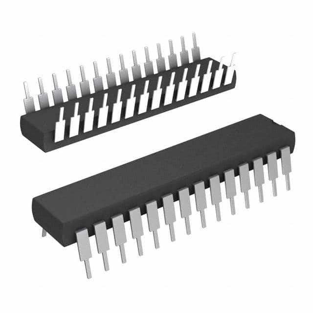
- Part No.:
- M5480B7
- Manufacturer:
- STMicroelectronics
- Category:
- ADCs/DACs - Special Purpose
- Package:
- 28-DIP (0.600", 15.24mm)
- Datasheet:
-
 M5480B7.pdf
- Description:
- IC DRVR 7 SEG 3 1/2 DIGIT 28DIP
- Quantity:
- Payment:

- Shipping:

Inventory:4,551
Please send an inquiry. Send us your inquiry, and we will respond immediately.
Product details
Overview
M5480B7 from STMicroelectronics is a 3½-digit LED display driver IC with 23-segment current-sink outputs, serial data interface (no load signal required), continuous brightness control via external resistor on pin 13, and wide supply range (4.75–13.2 V). It directly drives common-anode LED displays in microprocessor-based instrumentation readouts.
For engineers reviewing the M5480B7 datasheet, M5480B7 pinout, M5480B7 application, or M5480B7 equivalent, key selection factors include its 35-bit serial input format with embedded load/reset, ±20% output current matching, 0.5 MHz max clock frequency, and PDIP28 package compatibility with legacy MM5480 designs.
Technical Context
The M5480B7 integrates a 35-bit static master-slave shift register and 23-bit latch array, accepting serial data with a leading "1" start bit followed by 35 data bits; the 36th clock edge triggers internal LOAD and RESET signals to update outputs non-multiplexed. No external load signal is needed.
Brightness is set by analog current injection into pin 13 (VB = 3–4.3 V at 750 µA), generating ~20× scaled sink current per output (0–25 mA typical), with internal 400 Ω limiting resistor and mandatory 1 nF bypass capacitor to suppress oscillation.
Key Specifications
| Parameter | Value and Actual Design Meaning |
|---|---|
| Display Digits | 3½-digit, 23-segment direct-drive capability for alphanumeric LED displays |
| Supply Voltage | 4.75–13.2 V - supports both 5 V and higher-voltage industrial rails without level-shifting |
| Output Sink Current | 0–25 mA per segment at VB = 750 µA - enables uniform brightness across segments without external resistors |
| Serial Clock Max | 0.5 MHz - limits minimum data transfer time to 72 µs per 36-bit frame |
| Output Matching | ±20% - ensures consistent segment luminance without per-segment calibration |
| Operating Temp | –25°C to +85°C - qualified for industrial control panel environments |
| Package | PDIP28 - through-hole mounting compatible with legacy board layouts and manual rework |
Pinout & Package
Package: PDIP28 (Plastic Dual In-line Package), 28-pin, 0.6-inch width, 2.54 mm pitch.
| Pin/Terminal | Circuit Role | Design Meaning |
|---|---|---|
| 1–12, 14–23, 25–28 | Output Bit 1–23 | Current-sink drivers for individual LED segments; each capable of 0–25 mA sink under brightness control |
| 13 | Brightness Control | Analog input pin setting reference current (0–750 µA); output current scales ~20× with internal gain |
| 24 | Data In | Serial data input accepting 36-bit frame (start bit + 35 data bits) with TTL-compatible voltage thresholds |
| 25 | Clock In | CMOS/TTL-compatible clock input; rising edge shifts data, 36th edge triggers internal LOAD/RESET |
| 26 | VDD | Main power supply (4.75–13.2 V); powers logic and output buffers |
| 27 | VSS | Ground reference for logic and output stages; must be low-impedance return path |
Key Features
| Feature | Design Value |
|---|---|
| No external load signal required | Internal LOAD/RESET generated synchronously on 36th clock edge - eliminates timing-critical control lines |
| Current generator outputs | Integrated constant-current sinks eliminate need for 23 discrete current-limiting resistors - reduces BOM count and layout area |
| Continuous brightness control | Analog current input (pin 13) enables smooth, stepless dimming without PWM or digital register writes |
| TTL/CMOS compatible inputs | VIH = VDD – 2 V (for VDD > 5.25 V) and VIL = 0.08 V - interoperates directly with 5 V microcontrollers and FPGAs |
| Non-multiplexed drive | Latched 23-bit parallel output - avoids flicker, ghosting, or timing skew in static display applications |
Applications
| Microprocessor Display | Industrial Control Indication |
|---|---|
Use Scenario: 3½-digit numeric readout on PLC HMI panel with local MCU (e.g., STM32F103) driving 7-segment + decimal point LEDs. IC Role / Device Role / Timing Role: Serial-to-parallel LED driver converting MCU SPI-like bitstream into direct segment current control; no software-driven multiplexing required. Use Value: Reduces MCU GPIO usage from 23+ pins to 2 (DATA, CLOCK), eliminates timer-based refresh code, and ensures stable segment intensity across temperature. | Use Scenario: Status indicator on factory-floor relay I/O module showing channel activation, fault codes, or setpoint values. IC Role / Device Role / Timing Role: Standalone display controller interfacing to discrete logic or shift-register outputs; operates independently of host processor timing. Use Value: Enables reliable, low-maintenance visual feedback in electrically noisy environments where microcontroller resets may occur. |
| Instrumentation Readouts | Relay Driver Interface |
Use Scenario: Digital multimeter front-panel display showing measured voltage/current/resistance with 0.1% digit resolution. IC Role / Device Role / Timing Role: Precision segment driver with ±20% output matching - maintains consistent digit contrast without per-segment trimming. Use Value: Supports high-legibility static displays under varying ambient light, with brightness adjustable via single potentiometer. | Use Scenario: Driving LED status indicators for electromechanical relays in HVAC control cabinets, where long cable runs require robust current drive. IC Role / Device Role / Timing Role: High-current (up to 25 mA) segment sink enabling direct drive of LEDs over 10+ cm PCB traces without buffer transistors. Use Value: Eliminates discrete transistor drivers and base resistors, reducing component count and failure points in safety-critical indication paths. |
Equivalent & Alternatives
The following parts are listed as comparable options for similar LED display driver applications.
| Alternative Part | Technical Difference | Application Difference | Selection Advice |
|---|---|---|---|
| MM5480 | Pin-to-pin compatible, identical functional block diagram and serial protocol; same PDIP28 package and 23-output architecture | No difference - designed as direct drop-in replacement per datasheet | Select MM5480 only if legacy sourcing or dual-sourcing strategy requires National Semiconductor branding |
| MAX7219 | 8-digit, 64-segment driver with SPI interface, on-chip decoding, and shutdown mode; requires external current-setting resistor per digit | Supports multiplexed 8-digit displays but lacks non-multiplexed 3½-digit simplicity and analog brightness control | Choose MAX7219 only when expanding beyond 3½ digits or requiring integrated BCD decode and scan control |
Compared with MM5480, M5480B7 offers identical functionality and footprint; versus MAX7219, it trades digit count and SPI convenience for deterministic static drive, lower software overhead, and analog dimming - making it optimal for fixed-format industrial readouts.
Availability
M5480B7 is available at Aetrix Electronics and suitable for industrial control indication, instrumentation readouts, and microprocessor display applications requiring stable component supply and long-term obsolescence management.
Supply support for M5480B7 includes scheduled delivery planning, volume procurement assistance, BOM continuity management, traceable sourcing, and lifecycle availability coordination for OEM customers, industrial embedded developers, connected-device designers, and electronics production programs.
Manufacturer
STMicroelectronics is a global semiconductor leader headquartered in Geneva, designing and manufacturing analog, microcontroller, power, and sensor solutions for industrial, automotive, and consumer markets.
The M5480B7 belongs to ST's legacy LED display driver product line, engineered specifically for cost-sensitive, high-reliability 3½-digit static-display systems in industrial instrumentation and control panels.
FAQ
What is the function of the 1 nF capacitor on pin 13?
The 1 nF capacitor on pin 13 (Brightness Control) stabilizes the internal current reference amplifier and prevents high-frequency oscillation caused by parasitic inductance in the external brightness-setting resistor network. It must be placed as close as possible to pin 13 with short leads; omission risks erratic output current and visible display flicker.
Can M5480B7 drive common-cathode LED displays?
No - the M5480B7 provides only current-sink outputs (open-drain N-channel MOSFETs) and is designed exclusively for common-anode LED displays. Driving common-cathode displays would require external high-side switches or level-shifting circuitry not supported by the device architecture.
How does the M5480B7 handle incomplete 36-bit data frames?
If fewer than 36 clock edges are applied after the start bit, the internal shift registers do not clear and latching does not occur - resulting in stale or undefined segment states. The device requires exactly 36 clocks per frame; partial transfers leave outputs unchanged until a valid full frame is received.
Is thermal derating required when operating at 13.2 V with all 23 segments lit?
Yes - at VDD = 13.2 V and 25 mA per segment (575 mA total sink current), junction temperature exceeds 150 °C without heatsinking. Using the provided thermal equation (Tj = [(VOUT)(ILED)(N) + VDD·7 mA] × 132 °C/W + Tamb), design must limit active segments or reduce current to maintain Tj ≤ 150 °C at maximum ambient.
M5480B7 Specifications
- Product attributes
- Attribute value
- Manufacturer:
- STMicroelectronics
- Series:
- -
- Package/Case:
- 28-DIP (0.600", 15.24mm)
- Packaging:
- Tube
- Product Status:
- Obsolete
- Type:
- -
- Number of Channels:
- -
- Resolution (Bits):
- -
- Sampling Rate (Per Second):
- -
- Data Interface:
- -
- Voltage Supply Source:
- -
- Voltage - Supply:
- 4.75V ~ 13.2V
- Operating Temperature:
- -25°C ~ 85°C
- Mounting Type:
- Through Hole
- Grade:
- -
- Qualification:
- -
- Supplier Device Package:
- 28-PDIP
M5480B7 FAQ
1.How can I place an order for M5480B7 through Aetrix?
Please submit a Request for Quotation (RFQ) for M5480B7 on Aetrix. Our sales agent will provide a competitive quotation and guide you through the order confirmation once you accept the terms.
2.Are the price and stock information for M5480B7 reliable?
The price and inventory of M5480B7 are updated periodically and may fluctuate due to market conditions. Stock and pricing data are typically refreshed every 24 hours. Quotation validity for M5480B7 is usually 5 days.
3.What payment methods are accepted for M5480B7?
We accept Wire Transfer, PayPal, Credit Card, Western Union, MoneyGram, and Escrow for M5480B7 transactions.
Note: Certain payment methods may incur a processing fee.
4.How is shipping managed for M5480B7?
M5480B7 orders can be shipped via leading logistics carriers, including DHL, UPS, FedEx, TNT, or Registered Mail.
Once your M5480B7 order is processed, you will receive an email with the shipment details and tracking number.
Note: Tracking information may take up to 24 hours to appear. Express delivery typically takes 3–5 business days.
5.How can I obtain technical support or documentation for M5480B7?
For technical support, including M5480B7 datasheets, pinout diagrams, or application guidance, please contact our engineering support team. They can provide detailed documentation and assistance for your M5480B7 requirements.
6.How does Aetrix verify that M5480B7 is sourced from the original manufacturer or authorized distributors?
All M5480B7 products on Aetrix are procured from qualified distributors and authorized channels. Our dedicated quality assurance team conducts strict verification, including traceability checks and, if necessary, third-party testing. This ensures that M5480B7 meets industry standards.
7.What is the process for return or replacement of M5480B7?
All M5480B7 units undergo pre-shipment inspection (PSI). If there is an issue with M5480B7, returns or replacements are accepted under the following conditions:
1.Quantity discrepancies, incorrect items, or visible external defects (such as breakage or corrosion), acknowledged by Aetrix.
2.The issue is reported within 90 days of delivery.
3.The M5480B7 part is unused and in its original packaging.
Return procedure for M5480B7:
1.Submit a request within 90 days.
2.Obtain a Return Material Authorization (RMA) from Aetrix.
M5480B7 Tags

-
PCM1808PWR
Texas Instruments
-
PCM5121PWR
Texas Instruments

-
PCM5100APWR
Texas Instruments
-
AK4432VT
Asahi Kasei Microdevices/AKM
-
PCM1803ADBR
Texas Instruments
-
WM8524CGEDT/R
Cirrus Logic Inc.
-
AK5704EN
Asahi Kasei Microdevices/AKM
-
AK5720VT
Asahi Kasei Microdevices/AKM
-
WM8523GEDT/R
Cirrus Logic Inc.
-
PCM5102APWR
Texas Instruments
-
AMC1306M05DWVR
Texas Instruments
-
AMC1106M05DWVR
Texas Instruments
Tech Hub

A practical engineering and sourcing framework covering lifecycle verification, lifetime-buy calculations, replacement qualification, supplier checks and counterfeit-risk controls.

TTL and CMOS logic families differ in thresholds, loading, output drive, power and timing. This engineering guide compares 74HC and 74HCT, calculates noise margins and checks 3.3 V/5 V compatibility.

A practical engineering guide to 3.3V and 5V logic compatibility, input thresholds, resistor dividers, translator ICs, MOSFET level shifting, I2C pull-ups, timing limits and power-sequencing risks.

The 74HC595 uses push-pull logic outputs, while the TPIC6B595 uses 50 V open-drain DMOS sinks for higher-power loads. This guide compares timing, current limits, 3.3 V interfacing, load wiring, thermal…

The 74HC595 converts serial data into eight stable parallel outputs. This guide covers pin functions, shift and storage timing, OE and MR behavior, drive-current limits, cascading, voltage compatibilit…

A technical comparison of level-sensitive latches and edge-triggered flip-flops, covering timing windows, setup and hold limits, master–slave operation, time borrowing, race-through, HDL inference and…

A D latch stores one bit while Enable controls when data can pass. This reference covers gate-level operation, truth tables, transparency, setup and hold timing, LE versus OE, common ICs and practical …

An SR latch stores one bit through cross-coupled feedback. This engineering reference covers NOR and NAND implementations, truth tables, forbidden-state recovery, gated operation, switch debouncing, fa…

Latch circuits retain one bit through feedback. This technical reference covers SR and D latches, truth tables, transparency, timing limits, latch-versus-flip-flop behavior, applications and common log…

An engineering guide to LED driver operation, constant-current and constant-voltage outputs, linear and switching topologies, dimming, IC selection, calculations, replacement compatibility, and fault c…


