
 My Inquiry
 My Account


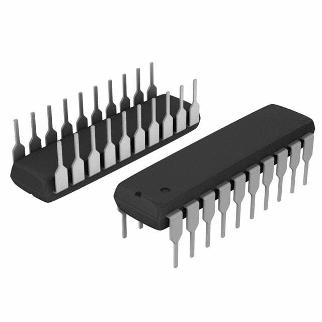
STMicroelectronics M5481B7
- Part No.:
- M5481B7
- Manufacturer:
- STMicroelectronics
- Category:
- Display Drivers
- Package:
- 20-DIP (0.300", 7.62mm)
- Datasheet:
-
 M5481B7.pdf
- Description:
- IC DRVR 7 SEGMENT 2 DIGIT 20DIP
- Quantity:
- Payment:

- Shipping:

Inventory:3,498
Please send an inquiry. Send us your inquiry, and we will respond immediately.
Product details
Overview
M5481B7 from STMicroelectronics is a 2-digit, 14-segment LED display driver IC with serial data interface, current-generator outputs (no external current-limiting resistors required), continuous brightness control via pin 9, TTL-compatible inputs, and wide supply voltage operation (4.5 V to 13.2 V). It serves as a pin-to-pin replacement for the NS MM5481 in microprocessor-based display systems.
For engineers reviewing the M5481B7 datasheet, M5481B7 pinout, M5481B7 application, or M5481B7 equivalent, key selection considerations include its 35-bit serial input format with embedded load/reset timing, ±20% output current matching, 0.5 MHz max clock frequency, and PDIP20 package suitability for industrial indicator and instrumentation readout designs.
Technical Context
The M5481B7 integrates a 35-bit static master-slave shift register, 35 latches, and 35 output buffers-though only 14 outputs are used for 2-digit alphanumeric displays. Its brightness control uses an internal 400 Ω reference resistor and external variable resistor + 1 nF capacitor on pin 9 to set sink current ranging from 0 mA to 25 mA per segment.
Data transfer requires a 36-clock cycle: a leading "1" start bit followed by 35 data bits; the 36th clock edge triggers synchronous load into latches, while the low clock state generates internal reset. No separate load signal is needed, enabling direct non-multiplexed LED drive.
Key Specifications
| Parameter | Value and Actual Design Meaning |
|---|---|
| Supply Voltage | 4.5 V to 13.2 V - supports wide-range industrial power rails without regulation |
| Output Sink Current | 0–25 mA per segment at pin 9 = 750 µA - enables direct LED drive without external resistors |
| Max Clock Frequency | 0.5 MHz - defines maximum serial update rate for dynamic display refresh |
| Output Matching | ±20% - ensures consistent segment brightness across all 14 driven outputs |
| Operating Temp | –25 °C to +85 °C - qualified for industrial control panel environments |
| Package | PDIP20 - through-hole mounting compatible with legacy PCB assembly |
| Input Compatibility | TTL - interfaces directly with standard microcontroller GPIO without level-shifting |
Pinout & Package
PDIP20 plastic dual in-line package with copper frame construction; 20-pin through-hole footprint (D = 25.4 mm, E = 8.5 mm, e = 2.54 mm).
| Pin/Terminal | Circuit Role | Design Meaning |
|---|---|---|
| 1 | Output Bit 9 | Segment driver output (e.g., decimal point or segment G) |
| 2 | Data Enable | Active-high enable for serial data capture; must be high during clock/data transfer |
| 3 | Data In | Serial data input (MSB-first, 35-bit payload + start bit) |
| 4 | Clock | Positive-edge-triggered serial clock; 36 edges complete one full load cycle |
| 5 | VDD | Main supply input (4.5–13.2 V); powers logic and output stages |
| 9 | Brightness Control | Analog current-setting input; external resistor + 1 nF capacitor sets reference for all 14 outputs |
| 10–20 | Output Bits 8–14, VSS | Segment drivers (pins 10–19) and ground (pin 20); pins 11–14 map to digit-specific segments |
Key Features
| Feature | Design Value |
|---|---|
| Current-generator outputs | Eliminates need for 14 discrete current-limiting resistors, reducing BOM count and board area |
| 35-bit serial interface with embedded load | Removes requirement for external LOAD or RESET signals-simplifies MCU GPIO usage |
| Continuous analog brightness control | Enables smooth dimming across temperature and supply variations using single external potentiometer |
| Internal power-on reset | Guarantees known initial state at power-up without external RC network |
| TTL-compatible inputs | Direct connection to 5 V microcontrollers (e.g., 8051, PIC16) without level translation circuitry |
Applications
| Microprocessor Display Systems | Industrial Control Indicators |
|---|---|
Use Scenario: 2-digit numeric display on PLC HMI panels showing process values (e.g., temperature, pressure). IC Role / Device Role / Timing Role: LED driver translating serial commands from ARM Cortex-M0+ MCU into direct segment drive signals. Use Value: Reduces MCU GPIO count by 14 pins and eliminates 14 current-setting resistors per display unit. | Use Scenario: Status indicator on factory-floor relay control modules showing ON/OFF/FAULT states. IC Role / Device Role / Timing Role: Static display driver receiving infrequent updates over UART-to-SPI bridge; holds state indefinitely. Use Value: Low IDD (7 mA at 13.2 V) minimizes standby power in always-on industrial enclosures. |
| Instrumentation Readouts | Legacy Equipment Upgrades |
Use Scenario: Digital multimeter front-panel display showing measured voltage/resistance with 2-digit resolution. IC Role / Device Role / Timing Role: Segment driver synchronized to ADC conversion completion via dedicated SPI line. Use Value: ±20% output matching ensures uniform segment luminance critical for readability under varying ambient light. | Use Scenario: Drop-in replacement for obsolete MM5481 in aging test equipment requiring same pinout and function. IC Role / Device Role / Timing Role: Pin-to-pin compatible LED driver maintaining identical serial protocol and timing behavior. Use Value: Eliminates PCB redesign and firmware changes-only component-level swap required. |
Equivalent & Alternatives
The following parts are listed as comparable options for similar LED display driver applications.
| Alternative Part | Technical Difference | Application Difference | Selection Advice |
|---|---|---|---|
| MM5481 | Original National Semiconductor part; identical pinout and serial protocol but discontinued and not RoHS-compliant | Same 2-digit, 14-segment drive capability; no brightness control via external resistor | Select M5481B7 for RoHS compliance, guaranteed supply, and enhanced brightness adjustability |
| MAX7219 | 8-digit, 7-segment driver with SPI interface, on-chip decoding, and digital brightness control; requires external current-limiting resistors | Higher digit count and integrated BCD decode, but lacks analog brightness tuning and uses different serial framing | Choose MAX7219 only when upgrading to 8-digit displays or requiring programmable scan rates |
Compared with MM5481 and MAX7219, the M5481B7 uniquely balances legacy compatibility, analog brightness control, and resistorless segment drive-making it optimal for cost-sensitive, 2-digit industrial indicators where design continuity matters.
Availability
M5481B7 is available at Aetrix Electronics and suitable for industrial control indicators, instrumentation readouts, and microprocessor display systems requiring stable component supply and long-term obsolescence management.
Supply support for M5481B7 includes scheduled delivery planning, volume procurement assistance, BOM continuity management, traceable sourcing, and lifecycle availability coordination for OEM customers, industrial embedded developers, connected-device designers, and electronics production programs.
Manufacturer
STMicroelectronics is a global semiconductor leader headquartered in Geneva, specializing in automotive, industrial, and power management ICs with strong analog and mixed-signal heritage.
The M5481B7 belongs to ST's legacy LED driver product line, designed specifically for cost-effective, through-hole-based alphanumeric display systems in industrial and instrumentation applications.
FAQ
What is the function of the 1 nF capacitor on pin 9?
The 1 nF capacitor on pin 9 stabilizes the internal reference current generator by filtering noise and preventing oscillation during analog brightness control. It must be placed as close as possible to pin 9 with short traces; ceramic type is recommended. Omitting it may cause erratic segment current or visible flicker.
Can M5481B7 drive common-anode LED displays?
No. The M5481B7 provides only sink-current outputs (open-drain N-channel MOSFETs), so it is designed exclusively for common-cathode LED displays. Driving common-anode displays would require external high-side switches or level-shifting circuitry not supported by the device architecture.
How does the 36-clock serial protocol work without a separate LOAD signal?
The M5481B7 uses the 36th clock edge to generate an internal synchronous LOAD pulse that transfers all 35 data bits from the shift register to the output latches. The start bit (logical "1") and precise 36-clock timing eliminate need for external LOAD-reducing MCU pin count and simplifying firmware.
Is thermal derating required for continuous operation?
Yes. At ambient temperatures above 25°C or with >7 segments lit simultaneously, junction temperature must be calculated using Tj = [(Vout × ILED × N) + (VDD × 7 mA)] × 80°C/W + Tamb. Exceeding 150°C risks permanent damage; use heatsinking or reduce segment count if Tj approaches limit.
M5481B7 Specifications
- Product attributes
- Attribute value
- Manufacturer:
- STMicroelectronics
- Series:
- -
- Package/Case:
- 20-DIP (0.300", 7.62mm)
- Packaging:
- Tube
- Product Status:
- Obsolete
- Display Type:
- LED
- Configuration:
- 7 Segment
- Interface:
- Serial
- Digits or Characters:
- 2 Digits
- Current - Supply:
- 7 mA
- Voltage - Supply:
- 4.5V ~ 13.2V
- Operating Temperature:
- -25°C ~ 85°C
- Grade:
- -
- Qualification:
- -
- Mounting Type:
- Through Hole
- Supplier Device Package:
- 20-DIP
M5481B7 FAQ
1.How can I place an order for M5481B7 through Aetrix?
Please submit a Request for Quotation (RFQ) for M5481B7 on Aetrix. Our sales agent will provide a competitive quotation and guide you through the order confirmation once you accept the terms.
2.Are the price and stock information for M5481B7 reliable?
The price and inventory of M5481B7 are updated periodically and may fluctuate due to market conditions. Stock and pricing data are typically refreshed every 24 hours. Quotation validity for M5481B7 is usually 5 days.
3.What payment methods are accepted for M5481B7?
We accept Wire Transfer, PayPal, Credit Card, Western Union, MoneyGram, and Escrow for M5481B7 transactions.
Note: Certain payment methods may incur a processing fee.
4.How is shipping managed for M5481B7?
M5481B7 orders can be shipped via leading logistics carriers, including DHL, UPS, FedEx, TNT, or Registered Mail.
Once your M5481B7 order is processed, you will receive an email with the shipment details and tracking number.
Note: Tracking information may take up to 24 hours to appear. Express delivery typically takes 3–5 business days.
5.How can I obtain technical support or documentation for M5481B7?
For technical support, including M5481B7 datasheets, pinout diagrams, or application guidance, please contact our engineering support team. They can provide detailed documentation and assistance for your M5481B7 requirements.
6.How does Aetrix verify that M5481B7 is sourced from the original manufacturer or authorized distributors?
All M5481B7 products on Aetrix are procured from qualified distributors and authorized channels. Our dedicated quality assurance team conducts strict verification, including traceability checks and, if necessary, third-party testing. This ensures that M5481B7 meets industry standards.
7.What is the process for return or replacement of M5481B7?
All M5481B7 units undergo pre-shipment inspection (PSI). If there is an issue with M5481B7, returns or replacements are accepted under the following conditions:
1.Quantity discrepancies, incorrect items, or visible external defects (such as breakage or corrosion), acknowledged by Aetrix.
2.The issue is reported within 90 days of delivery.
3.The M5481B7 part is unused and in its original packaging.
Return procedure for M5481B7:
1.Submit a request within 90 days.
2.Obtain a Return Material Authorization (RMA) from Aetrix.
M5481B7 Tags

-
PCA8561AHN/AY
NXP Semiconductors

-
SN74LS47N
Texas Instruments

-
PCF85176T/1Y
NXP Semiconductors
-
PCF85176H/1,518
NXP Semiconductors

-
BU9796AMUV-E2
Rohm Semiconductor
-
PCA85176H/Q900/1,5
NXP Semiconductors
-
PCF8537AH/1,518
NXP Semiconductors

-
LM3914VX/NOPB
Texas Instruments

-
PCF85134HL/1,118
NXP Semiconductors

-
AS1115-BSST
ams-OSRAM USA INC.
-
PCA8534AH/Q900/1,5
NXP Semiconductors
-
LM3914V/NOPB
Texas Instruments
Tech Hub

A practical engineering and sourcing framework covering lifecycle verification, lifetime-buy calculations, replacement qualification, supplier checks and counterfeit-risk controls.

TTL and CMOS logic families differ in thresholds, loading, output drive, power and timing. This engineering guide compares 74HC and 74HCT, calculates noise margins and checks 3.3 V/5 V compatibility.

A practical engineering guide to 3.3V and 5V logic compatibility, input thresholds, resistor dividers, translator ICs, MOSFET level shifting, I2C pull-ups, timing limits and power-sequencing risks.

The 74HC595 uses push-pull logic outputs, while the TPIC6B595 uses 50 V open-drain DMOS sinks for higher-power loads. This guide compares timing, current limits, 3.3 V interfacing, load wiring, thermal…

The 74HC595 converts serial data into eight stable parallel outputs. This guide covers pin functions, shift and storage timing, OE and MR behavior, drive-current limits, cascading, voltage compatibilit…

A technical comparison of level-sensitive latches and edge-triggered flip-flops, covering timing windows, setup and hold limits, master–slave operation, time borrowing, race-through, HDL inference and…

A D latch stores one bit while Enable controls when data can pass. This reference covers gate-level operation, truth tables, transparency, setup and hold timing, LE versus OE, common ICs and practical …

An SR latch stores one bit through cross-coupled feedback. This engineering reference covers NOR and NAND implementations, truth tables, forbidden-state recovery, gated operation, switch debouncing, fa…

Latch circuits retain one bit through feedback. This technical reference covers SR and D latches, truth tables, transparency, timing limits, latch-versus-flip-flop behavior, applications and common log…

An engineering guide to LED driver operation, constant-current and constant-voltage outputs, linear and switching topologies, dimming, IC selection, calculations, replacement compatibility, and fault c…


