
 My Inquiry
 My Account


Renesas M61531FP#RF0G
- Part No.:
- M61531FP#RF0G
- Manufacturer:
- Renesas
- Category:
- Audio Special Purpose
- Package:
- -
- Datasheet:
-
 M61531FP#RF0G.pdf
- Description:
- AUDIO CONTROL IC, PQFP80
- Quantity:
- Payment:

- Shipping:

Inventory:3,352
Please send an inquiry. Send us your inquiry, and we will respond immediately.
Product details
Overview
M61531FP#RF0G from Renesas Electronics is a 6-channel electronic volume IC with 10-input stereo selector, tone control (±16 dB bass, ±10 dB treble), built-in loudness circuit, and 4-line REC output. It operates from ±7 V analog supplies and 2.7–5.5 V digital supply, delivering <0.05% THD at 0.3 Vrms output, and targets high-fidelity audio signal routing and level management in multi-source AV systems.
For engineers reviewing the M61531FP#RF0G datasheet, M61531FP#RF0G pinout, M61531FP#RF0G application, or M61531FP#RF0G equivalent, key selection criteria include its 0 to –99 dB/1 dB step volume resolution, 3-wire MCU interface timing (min. 4 µs clock cycle), ±7 V analog rail tolerance, JIS-A weighted noise floor of 9–25 µVrms, and support for external L/R bypass input selection.
Technical Context
The M61531FP#RF0G integrates six independent digitally controlled analog volume channels using high-voltage transistor attenuation, each supporting precise 1 dB steps from 0 to –99 dB plus mute (–∞ dB). Its input path includes dual-stage selection: a primary 10-input L/R selector and a secondary 2-input per-channel multi-selector (C, SW, SR, SL, L, R).
Tone processing is implemented via discrete BASS/TREBLE pins with programmable gain settings (–16/+16 dB bass, –10/+10 dB treble), selectable tone block position (pre- or post-volume), and configurable tone input attenuation (0/–6/–12/–18 dB). Loudness compensation uses center-tap topology with on/off control and balance output capability.
Key Specifications
| Parameter | Value and Actual Design Meaning |
|---|---|
| Volume Range | 0 to –99 dB in 1 dB steps + mute (–∞ dB); enables precise channel-level balancing across 6 audio paths. |
| Analog Supply | AVCC = +7.0 V (typ.), AVEE = –7.0 V (typ.); supports ±7 V rails for low-distortion analog signal handling. |
| Digital Supply | DVDD = 2.7–5.5 V; compatible with 3.3 V or 5 V logic interfaces without level shifting. |
| THD+N | 0.005% (typ.) at 0.3 Vrms, 1 kHz; ensures high-fidelity audio reproduction in consumer AV equipment. |
| Channel Separation | –90 dB (min.) between input selectors; prevents crosstalk in multi-source receiver architectures. |
| Control Interface | 3-wire serial (CLOCK/DATA/LATCH); requires ≥4 µs clock cycle and ≥1.6 µs pulse widths for reliable MCU communication. |
| Input Impedance | 47 kΩ (typ.); matches standard line-level source impedances without loading effects. |
Pinout & Package
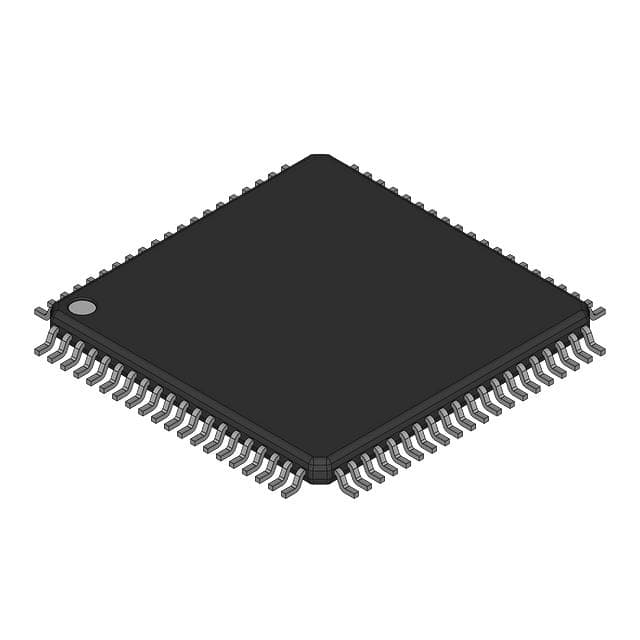
Package: 80-pin plastic QFP (14 mm × 20 mm, 0.65 mm pitch), RoHS-compliant, surface-mount.
| Pin/Terminal | Circuit Role | Design Meaning |
|---|---|---|
| INL1/EXT INL, INR1/EXT INR (Pins 4,5) | L/R channel primary input / external bypass input | Enables direct external analog source injection while retaining full volume/tone control. |
| LOUT, ROUT, COUT, SWOUT, SROUT, SLOUT (Pins 54,47,36,35,42,41) | Main channel outputs | Drive 10 kΩ loads at up to 4.2 Vrms; support simultaneous 6-channel playback with <0.5 dB gain matching. |
| BALANCE L/+, LOUD L/BALANCE L/– (Pins 14,15) | L-channel balance/loudness output pair | Provides differential loudness tap or balanced output; eliminates need for external op-amp summing. |
| CLOCK, DATA, LATCH (Pins 27,28,29) | 3-wire digital control interface | Accepts 3.3 V or 5 V logic; data latched on rising edge of LATCH after 24-bit serial load on CLOCK rising edges. |
| AVCC, AVEE, DVDD, DGND, GND (Pins 31,67,30,26,6,13,16,19,32,57,64) | Analog/digital power and ground | Separate analog/digital grounds prevent noise coupling; AVEE must be ≤ DGND < DVDD ≤ AVCC per spec. |
Key Features
| Feature | Design Value |
|---|---|
| 6-channel independent volume control | Each channel adjustable 0 to –99 dB in 1 dB steps with mute; critical for speaker-level calibration in 5.1/6.1 systems. |
| 10-input stereo selector + 2-input per-channel multi-selector | Supports 10 distinct source pairs (e.g., CD, tuner, phono) plus dedicated C/SW/SR/SL inputs for surround decoding. |
| Programmable tone control | ±16 dB bass (100 Hz) and ±10 dB treble (10 kHz) with pre/post-volume placement; meets Hi-Fi equalization requirements. |
| Center-tap loudness circuit | Compensates for human ear sensitivity at low volumes without external components; activated via single control bit. |
| 4-line REC output with independent L/R switching | Recovers pre-volume, pre-tone signals for recording; REC1–REC4 configurable per channel group via register bits D6a–D9a. |
| Input/output gain control (±18 dB) | Adjusts signal headroom before and after volume stage; prevents clipping in high-gain or low-sensitivity source scenarios. |
Applications
| Home Theater Receiver | Multi-Zone Audio Amplifier |
|---|---|
Use Scenario: Integrated AV receiver managing 10 analog sources (CD, Blu-ray, game console, streaming box) with 6.1 channel output and real-time loudness compensation. IC Role / Device Role / Timing Role: Central audio signal router and level manager; handles input selection, volume, tone, and REC routing under MCU command. Use Value: Eliminates 6 discrete potentiometers and external tone networks; reduces BOM cost by >40% versus discrete solutions while improving channel matching. | Use Scenario: Commercial audio system distributing synchronized audio to 3 independent zones (living room, kitchen, patio) with zone-specific volume and tone. IC Role / Device Role / Timing Role: Multi-channel volume and gain controller; provides independent L/R volume per zone plus shared C/SW/SR/SL paths for surround content. Use Value: Enables single-board design for multi-zone control; 0.5 dB channel gain matching ensures consistent perceived loudness across zones. |
| Hi-Fi Stereo Preamp | Professional Audio Monitor Controller |
Use Scenario: High-end stereo preamplifier with phono, DAC, and streamer inputs, requiring ultra-low-noise volume control and loudness compensation. IC Role / Device Role / Timing Role: Precision analog volume core with JIS-A weighted noise floor of 9–25 µVrms; supports external L/R bypass for critical-path sources. Use Value: Delivers <0.05% THD at 0.3 Vrms output-meets RIAA phono stage interface specs without additional buffering. | Use Scenario: Studio monitor controller switching between near-field, mid-field, and subwoofer outputs while maintaining calibrated reference levels. IC Role / Device Role / Timing Role: Calibration-grade volume attenuator with –99 dB range and 1 dB resolution; REC outputs feed metering circuits without affecting main signal path. Use Value: Enables traceable level calibration across all outputs; tone controls allow quick spectral adjustment during mixing sessions. |
Equivalent & Alternatives
The following parts are listed as comparable options for similar 6-channel audio volume control applications.
| Alternative Part | Technical Difference | Application Difference | Selection Advice |
|---|---|---|---|
| AK4118VN | 8-channel I²C-controlled volume (–100 dB range), no tone control or loudness; requires external 5 V analog supply. | Lacks integrated tone/loudness; suited for digital-centric designs where tone is handled upstream. | Select when I²C interface and higher channel count outweigh need for analog tone features. |
| CS4361-KQZ | 6-channel DAC + volume (–100 dB), integrated 24-bit DAC; no analog input selector or REC outputs. | Replaces analog front-end with digital conversion; requires SPDIF/I²S input instead of line-level analog. | Choose when system already uses digital audio transport and DAC integration reduces component count. |
Compared with AK4118VN and CS4361-KQZ, the M61531FP#RF0G uniquely combines 10-input analog selection, tone control, loudness, and REC routing in a single ±7 V analog volume IC-making it optimal for legacy analog source aggregation without DAC conversion.
Availability
M61531FP#RF0G is available at Aetrix Electronics and suitable for home theater receivers, multi-zone audio amplifiers, and Hi-Fi stereo preamps requiring stable component supply, long-lifecycle availability, and guaranteed RoHS compliance.
Supply support for M61531FP#RF0G includes scheduled delivery planning, volume procurement assistance, BOM continuity management, traceable sourcing, and lifecycle availability coordination for OEM customers, industrial embedded developers, connected-device designers, and electronics production programs.
Manufacturer
Renesas Electronics Corporation is a global semiconductor leader specializing in microcontrollers, analog, and power devices for automotive, industrial, and consumer applications.
The M61531FP#RF0G belongs to Renesas' legacy audio signal processing product line, designed specifically for high-fidelity analog audio routing, level control, and tone enhancement in consumer AV equipment.
FAQ
What is the maximum analog supply voltage rating for the M61531FP#RF0G?
The M61531FP#RF0G has an absolute maximum analog supply rating of AVCC–AVEE = ±8.0 V. The recommended operating range is AVCC = +4.5 to +7.5 V and AVEE = –7.5 to –4.5 V, with +7.0 V / –7.0 V being the typical bias point. Exceeding ±8.0 V risks permanent damage to the internal high-voltage transistors used in the volume attenuation circuitry of the M61531FP#RF0G.
Does the M61531FP#RF0G support I²C or only 3-wire serial control?
The M61531FP#RF0G supports only the proprietary 3-wire serial interface (CLOCK/DATA/LATCH) with fixed 24-bit frame format and timing requirements (min. 4 µs clock cycle). It does not implement I²C, SMBus, or SPI protocols. Control data must be shifted in MSB-first on the rising edge of CLOCK, then latched on the rising edge of LATCH to update registers in the M61531FP#RF0G.
What is the function of pins 14, 15, 17, and 18 on the M61531FP#RF0G?
Pins 14 and 15 are BALANCE L/+ and LOUD L/BALANCE L/–, forming a differential output pair for left-channel balance or loudness tap. Pins 17 and 18 serve the same function for the right channel (BALANCE R/+ and LOUD R/BALANCE R/–). These pins enable hardware-level balance adjustment or loudness compensation without external op-amps, and their operation is controlled by register bits D13d and D14d in the M61531FP#RF0G configuration space.
Can the M61531FP#RF0G drive headphones directly?
No, the M61531FP#RF0G is not designed to drive headphones directly. Its outputs (e.g., LOUT, ROUT) are line-level (max 4.2 Vrms into 10 kΩ) with 47 kΩ output impedance-intended for connection to power amplifier inputs, not low-impedance headphone loads. Driving headphones would require external buffer amplifiers. The M61531FP#RF0G's architecture focuses on signal routing and level control within AV receivers, not current delivery.
How does the loudness circuit in the M61531FP#RF0G operate?
The M61531FP#RF0G implements a center-tap loudness circuit that applies frequency-dependent boost below ~1 kHz to compensate for reduced human ear sensitivity at low listening volumes. Activation is controlled by bit D13d; when enabled, it modifies the L/R channel signal path using internal RC networks tied to pins 15 and 18. The circuit operates independently of tone controls and requires no external components-its behavior is fully defined in the M61531FP#RF0G datasheet section "Loudness" on page 8.
M61531FP#RF0G Specifications
- Product attributes
- Attribute value
- Manufacturer:
- Renesas
- Series:
- *
- Package/Case:
- -
- Packaging:
- Bulk
- Product Status:
- Active
- Function:
- -
- Applications:
- -
- Number of Channels:
- -
- Interface:
- -
- Voltage - Supply:
- -
- Operating Temperature:
- -
- Specifications:
- -
- Mounting Type:
- -
- Grade:
- -
M61531FP#RF0G FAQ
1.How can I place an order for M61531FP#RF0G through Aetrix?
Please submit a Request for Quotation (RFQ) for M61531FP#RF0G on Aetrix. Our sales agent will provide a competitive quotation and guide you through the order confirmation once you accept the terms.
2.Are the price and stock information for M61531FP#RF0G reliable?
The price and inventory of M61531FP#RF0G are updated periodically and may fluctuate due to market conditions. Stock and pricing data are typically refreshed every 24 hours. Quotation validity for M61531FP#RF0G is usually 5 days.
3.What payment methods are accepted for M61531FP#RF0G?
We accept Wire Transfer, PayPal, Credit Card, Western Union, MoneyGram, and Escrow for M61531FP#RF0G transactions.
Note: Certain payment methods may incur a processing fee.
4.How is shipping managed for M61531FP#RF0G?
M61531FP#RF0G orders can be shipped via leading logistics carriers, including DHL, UPS, FedEx, TNT, or Registered Mail.
Once your M61531FP#RF0G order is processed, you will receive an email with the shipment details and tracking number.
Note: Tracking information may take up to 24 hours to appear. Express delivery typically takes 3–5 business days.
5.How can I obtain technical support or documentation for M61531FP#RF0G?
For technical support, including M61531FP#RF0G datasheets, pinout diagrams, or application guidance, please contact our engineering support team. They can provide detailed documentation and assistance for your M61531FP#RF0G requirements.
6.How does Aetrix verify that M61531FP#RF0G is sourced from the original manufacturer or authorized distributors?
All M61531FP#RF0G products on Aetrix are procured from qualified distributors and authorized channels. Our dedicated quality assurance team conducts strict verification, including traceability checks and, if necessary, third-party testing. This ensures that M61531FP#RF0G meets industry standards.
7.What is the process for return or replacement of M61531FP#RF0G?
All M61531FP#RF0G units undergo pre-shipment inspection (PSI). If there is an issue with M61531FP#RF0G, returns or replacements are accepted under the following conditions:
1.Quantity discrepancies, incorrect items, or visible external defects (such as breakage or corrosion), acknowledged by Aetrix.
2.The issue is reported within 90 days of delivery.
3.The M61531FP#RF0G part is unused and in its original packaging.
Return procedure for M61531FP#RF0G:
1.Submit a request within 90 days.
2.Obtain a Return Material Authorization (RMA) from Aetrix.
M61531FP#RF0G Tags

-
SA571DR2G
onsemi

-
ADAU7002ACBZ-R7
Analog Devices Inc.

-
DRV135UA/2K5
Texas Instruments

-
DRV134UA/1K
Texas Instruments

-
DRV134PA
Texas Instruments
-
DRV134UA
Texas Instruments
-
DRV135UA
Texas Instruments
-
SA572DR2G
onsemi
-
PGA2311U/1K
Texas Instruments

-
SI8244BB-D-IS1R
Skyworks Solutions Inc.

-
CS8416K-CZZR
Cirrus Logic Inc.

-
SRC4392IPFBR
Texas Instruments
Tech Hub

TTL and CMOS logic families differ in thresholds, loading, output drive, power and timing. This engineering guide compares 74HC and 74HCT, calculates noise margins and checks 3.3 V/5 V compatibility.

A practical engineering guide to 3.3V and 5V logic compatibility, input thresholds, resistor dividers, translator ICs, MOSFET level shifting, I2C pull-ups, timing limits and power-sequencing risks.

The 74HC595 uses push-pull logic outputs, while the TPIC6B595 uses 50 V open-drain DMOS sinks for higher-power loads. This guide compares timing, current limits, 3.3 V interfacing, load wiring, thermal…

The 74HC595 converts serial data into eight stable parallel outputs. This guide covers pin functions, shift and storage timing, OE and MR behavior, drive-current limits, cascading, voltage compatibilit…

A technical comparison of level-sensitive latches and edge-triggered flip-flops, covering timing windows, setup and hold limits, master–slave operation, time borrowing, race-through, HDL inference and…

A D latch stores one bit while Enable controls when data can pass. This reference covers gate-level operation, truth tables, transparency, setup and hold timing, LE versus OE, common ICs and practical …

An SR latch stores one bit through cross-coupled feedback. This engineering reference covers NOR and NAND implementations, truth tables, forbidden-state recovery, gated operation, switch debouncing, fa…

Latch circuits retain one bit through feedback. This technical reference covers SR and D latches, truth tables, transparency, timing limits, latch-versus-flip-flop behavior, applications and common log…

An engineering guide to LED driver operation, constant-current and constant-voltage outputs, linear and switching topologies, dimming, IC selection, calculations, replacement compatibility, and fault c…

Operational amplifier guide covering op amp basics, feedback, ideal vs real op amps, common configurations, buffer circuits, offset, bias current, gain-bandwidth, slew rate, rail-to-rail limits and sel…


