
 My Inquiry
 My Account


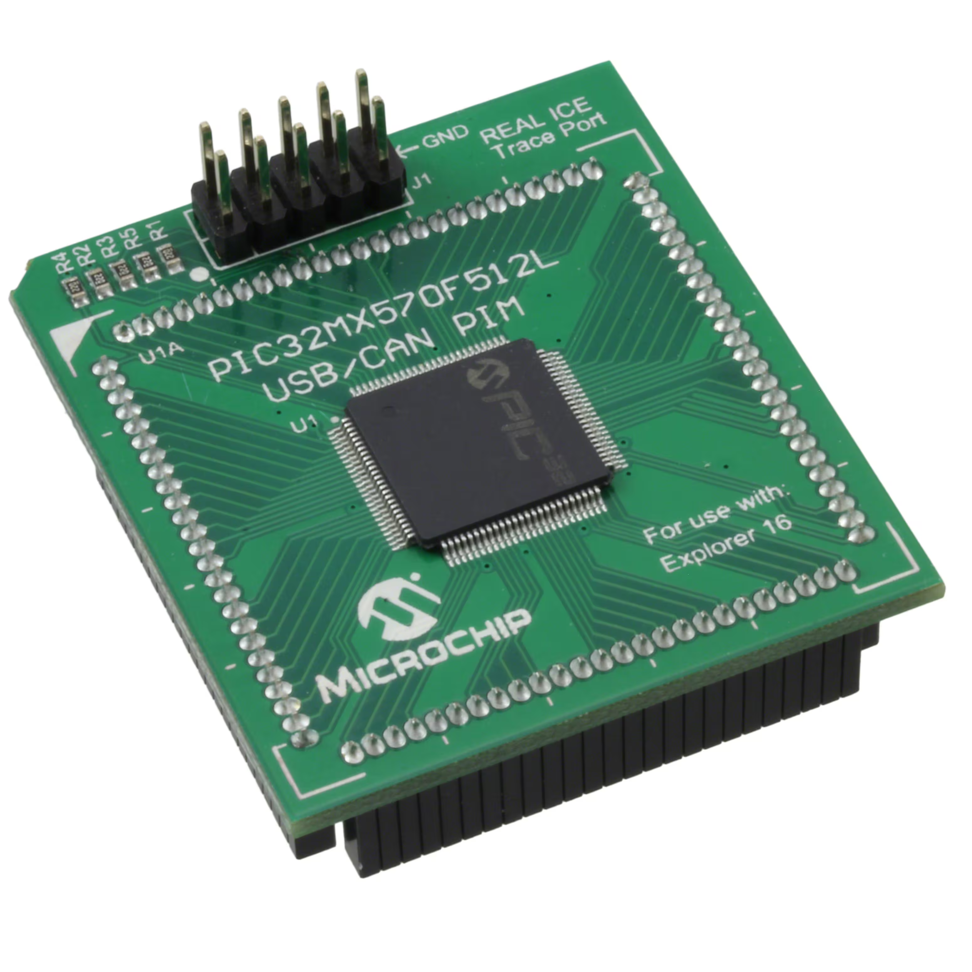
Microchip Technology MA320017
- Part No.:
- MA320017
- Manufacturer:
- Microchip Technology
- Category:
- Accessories
- Package:
- Datasheet:
-
 MA320017.pdf
- Description:
- PIC32MX270F512L PIM FOR BT ADK
- Quantity:
- Payment:

- Shipping:

Inventory:2,950
Please send an inquiry. Send us your inquiry, and we will respond immediately.
Product details
Overview
MA320017 from Microchip Technology is a 100-pin TQFP Plug-In Module (PIM) housing the PIC32MX270F512L 32-bit microcontroller, designed exclusively for use with the PIC32 Bluetooth Audio Development Board. It integrates USB 2.0 Full-Speed device interface, 512 KB Flash, 64 KB RAM, and analog peripherals including 16-channel 10-bit ADC, supporting Bluetooth audio streaming and embedded control in compact audio systems.
For engineers reviewing the MA320017 datasheet, MA320017 pinout, MA320017 application, or MA320017 equivalent, this module enables rapid evaluation of PIC32MX270F512L-based Bluetooth audio firmware, USB audio class (UAC) stack integration, and mixed-signal peripheral co-optimization without custom PCB design.
Technical Context
The MA320017 implements a MIPS32 M4K core running at up to 50 MHz, with integrated USB 2.0 PHY and dedicated USB ID detection (USBID/RF3), VBUS sensing (AN5/VBUSON/RPB5), and USB transceiver pins (D+/D−). Its analog subsystem includes dual 10-bit ADC modules with up to 16 input channels and programmable voltage reference (VREF+/VREF−).
It supports synchronous serial interfaces including four SPI modules (SCK1–SCK4), two I²C modules (SCL1/SDA1, SCL2/SDA2), and three UARTs - all mapped directly to PIM pins per Table 1. The module provides full trace port access (TRCLK, TRD0–TRD3) and JTAG debugging via PGED/PGEC pins.
Key Specifications
| Parameter | Value and Actual Design Meaning |
|---|---|
| CPU Core | MIPS32 M4K @ 50 MHz - delivers deterministic real-time execution for Bluetooth audio packet handling and USB isochronous transfers. |
| Memory | 512 KB Flash / 64 KB RAM - sufficient for dual-role firmware (USB audio + Bluetooth stack) with buffer space for PCM data streams. |
| USB Interface | USB 2.0 Full-Speed device only - supports USB Audio Class v1.0 with integrated PHY, requiring no external transceiver. |
| ADC | 16-channel 10-bit SAR ADC - enables simultaneous monitoring of battery voltage, microphone bias, and audio line-in levels. |
| Package | 100-pin TQFP (PIC32MX270F512L-50I/PT) - matches development board socket footprint with 0.5 mm pitch for reliable plug-in operation. |
| Supply Voltage | 3.3 V ±5% digital supply - compatible with standard USB-powered development environments and regulated 3.3 V system rails. |
| Debug Interface | 4-wire JTAG (TCK/TMS/TDI/TDO) + 2-wire SWD (PGED/PGEC) - enables full-speed firmware download and real-time trace via MPLAB ICD 4 or REAL ICE. |
Pinout & Package
The MA320017 uses a 100-pin TQFP package (14 × 14 mm, 0.5 mm pitch) with exposed thermal pad, matching the PIC32MX270F512L-50I/PT die. All pins are electrically and mechanically identical to the underlying MCU, routed 1:1 to the PIM edge connector per Table 1 in DS50002314A.
| Pin/Terminal | Circuit Role | Design Meaning |
|---|---|---|
| 1, 2, 13, 15, 16, 28, 29, 30, 31, 36, 37, 45, 46, 62, 65, 75, 85, 86 | Power/Ground | VDD (3.3 V), AVDD (analog supply), VSS/AVSS (digital/analog ground), VCAP (decoupling for internal regulator), enabling stable MCU operation and low-noise ADC conversion. |
| 54, 55, 56, 57 | USB Physical Layer | VBUS (detection), VUSB3V3 (regulator output), D+, D− (differential USB 2.0 FS signals) - fully compliant with USB specification without external components. |
| 38, 60, 61, 63, 64 | JTAG/SWD Debug | TCK/CTED2, TDI/CTED9, TDO/RA5, OSC1/CLKI, OSC2/CLKO - supports boundary scan, flash programming, and clock source validation during bring-up. |
| 58, 59, 66, 67 | I²C Interfaces | SCL2/RA2, SDA2/RA3, SCL1/RPA14, SDA1/RPA15 - allows connection to external codecs, EEPROMs, or sensor hubs using standard I²C protocol. |
| 91–92, 95–97 | Trace Port | TRCLK, TRD0–TRD3 - provides real-time instruction trace for performance profiling and latency analysis in audio pipeline development. |
Key Features
| Feature | Design Value |
|---|---|
| Bluetooth Audio Reference Platform | Pre-integrated hardware platform for PIC32MX270F512L enabling immediate evaluation of Bluetooth A2DP sink/source and USB audio bridging functionality. |
| 1:1 Pin Mapping | All 100 MCU pins exposed identically on PIM edge connector - eliminates signal routing ambiguity and guarantees register-level compatibility with target schematic. |
| Dual USB/Bluetooth Coexistence | Simultaneous USB device and Bluetooth baseband support via dedicated peripherals - avoids resource contention in dual-interface audio applications. |
| On-board Power Conditioning | Integrated 3.3 V regulation and multi-stage decoupling (0.01 µF, 0.1 µF, 10 µF) - ensures clean power delivery for sensitive analog and RF sections. |
| Trace & Debug Ready | Full 5-pin trace port (TRCLK/TRD0–TRD3) and 6-pin JTAG header footprint - enables cycle-accurate timing analysis and non-intrusive firmware inspection. |
Applications
| Bluetooth Audio Streaming | USB Audio Interface |
|---|---|
Use Scenario: Wireless playback of stereo PCM audio from smartphone to speaker system using A2DP profile. IC Role / Device Role / Timing Role: PIC32MX270F512L acts as Bluetooth baseband processor and audio decoder, synchronizing I²S output to external DAC while managing USB audio class descriptors. Use Value: Enables sub-100 ms end-to-end latency with hardware-accelerated SBC decoding and direct I²S-to-DAC path. | Use Scenario: PC-connected USB microphone array with multi-channel analog input and digital beamforming. IC Role / Device Role / Timing Role: MA320017 serves as USB audio class-compliant device controller, sampling four analog mics via ADC and packing data into isochronous USB packets. Use Value: Delivers 48 kHz/16-bit 4-channel audio with <5 µs inter-channel skew using hardware DMA and USB endpoint buffering. |
| Audio Codec Control Hub | Embedded Voice Assistant Node |
Use Scenario: Central controller managing multiple I²C-connected audio codecs, amplifiers, and GPIO-based status LEDs in smart speaker design. IC Role / Device Role / Timing Role: PIC32MX270F512L functions as system manager, coordinating codec initialization, volume control, and mute sequencing via I²C and PWM outputs. Use Value: Reduces BOM count by eliminating discrete I²C bus expanders and logic glue; supports runtime reconfiguration of audio paths. | Use Scenario: Low-power always-on voice wake-word detector interfacing with MEMS mic and cloud offload via Bluetooth LE. IC Role / Device Role / Timing Role: MA320017 executes lightweight neural network inference on ADC samples while maintaining Bluetooth LE advertising and connection states. Use Value: Achieves <200 µA sleep current with fast wake-up (<100 µs) to process trigger words, leveraging hardware CRC and DMA for efficient preprocessing. |
Equivalent & Alternatives
The following parts are listed as comparable options for similar microcontroller plug-in module applications.
| Alternative Part | Technical Difference | Application Difference | Selection Advice |
|---|---|---|---|
| MA320016 | Based on PIC32MX170F256B - 256 KB Flash, 64 KB RAM, no USB PHY, 64-pin TQFP. | Lacks USB 2.0 device interface and Bluetooth audio reference firmware support; suitable only for non-USB sensor hub or motor control PIMs. | Select MA320016 only when USB connectivity and audio-class compliance are unnecessary and board space is constrained. |
| MA320018 | Based on PIC32MZ2048ECG100 - 2 MB Flash, 512 KB RAM, DDR interface, crypto engine, 100-pin TQFP. | Supports higher-bandwidth audio (e.g., aptX HD, LDAC) and secure OTA updates but requires external DDR memory and more complex power sequencing. | Choose MA320018 for next-generation Bluetooth audio with advanced codecs and firmware security requirements. |
Compared with MA320016 and MA320018, MA320017 strikes a balance between USB audio readiness, Bluetooth stack compatibility, and cost-effective memory sizing - making it optimal for production-ready Bluetooth speaker and headset reference designs without over-engineering.
Availability
MA320017 is available at Aetrix Electronics and suitable for Bluetooth audio development, USB audio interface prototyping, and embedded voice processing applications requiring stable component supply and full debug accessibility.
Supply support for MA320017 includes scheduled delivery planning, volume procurement assistance, BOM continuity management, traceable sourcing, and lifecycle availability coordination for OEM customers, industrial embedded developers, connected-device designers, and electronics production programs.
Manufacturer
Microchip Technology Inc. is a U.S.-based semiconductor manufacturer specializing in microcontrollers, analog devices, and development tools, with ISO/TS-16949 certified fabrication and design operations.
The PIC32MX family targets cost-sensitive, high-performance embedded applications requiring rich peripheral sets and USB connectivity - specifically optimized for audio, motor control, and human interface devices.
FAQ
What is the primary function of the MA320017 plug-in module?
The MA320017 plug-in module hosts the PIC32MX270F512L microcontroller and is engineered exclusively for the PIC32 Bluetooth Audio Development Board. It provides full electrical and mechanical compatibility with the target MCU, enabling rapid firmware development, USB audio class testing, and Bluetooth A2DP streaming evaluation without custom PCB layout. MA320017 retains all native peripherals including USB 2.0 Full-Speed, 16-channel ADC, and trace/debug interfaces.
Does the MA320017 include an onboard USB transceiver?
Yes, the MA320017 integrates the PIC32MX270F512L's native USB 2.0 Full-Speed device transceiver, with dedicated D+ and D− pins routed directly to the PIM edge connector. No external PHY or level-shifting components are required. MA320017 supports USB Audio Class v1.0 descriptors out-of-box when used with Microchip's MLA stack and the designated development board.
Can the MA320017 be used outside the PIC32 Bluetooth Audio Development Board?
No - the MA320017 is explicitly designed for use only with the PIC32 Bluetooth Audio Development Board, as stated in DS50002314A-page 1. Its pinout, power delivery, and signal routing assume the host board's 100-pin socket, USB power architecture, and trace/debug header layout. Using MA320017 on other carriers may result in missing VBUS detection, incorrect USB termination, or unconnected trace signals.
What debug and trace capabilities does the MA320017 support?
The MA320017 supports full 4-wire JTAG (TCK/TMS/TDI/TDO), 2-wire SWD (PGED/PGEC), and 5-pin trace port (TRCLK/TRD0–TRD3) as implemented by the PIC32MX270F512L. These interfaces are accessible via standard headers on the development board and enable real-time instruction tracing, cycle-accurate profiling, and non-intrusive firmware debugging using MPLAB ICD 4 or REAL ICE tools. MA320017 preserves all trace bandwidth and timing fidelity of the underlying MCU.
Is the MA320017 RoHS compliant and lead-free?
Yes, the MA320017 conforms to RoHS Directive 2011/65/EU and uses lead-free solder finish on its 100-pin TQFP package. The PIC32MX270F512L-50I/PT die inside meets Microchip's standard environmental compliance requirements, including halogen-free laminate and Pb-free terminations. Documentation confirming compliance is available in Microchip's part-specific declaration reports for MA320017.
MA320017 Specifications
- Product attributes
- Attribute value
- Manufacturer:
- Microchip Technology
- Series:
- -
- Packaging:
- Bulk
- Product Status:
- Active
- Accessory Type:
- Plug-In Module (PIM)
- For Use With/Related Products:
- PIC32MX270F512L
MA320017 FAQ
1.How can I place an order for MA320017 through Aetrix?
Please submit a Request for Quotation (RFQ) for MA320017 on Aetrix. Our sales agent will provide a competitive quotation and guide you through the order confirmation once you accept the terms.
2.Are the price and stock information for MA320017 reliable?
The price and inventory of MA320017 are updated periodically and may fluctuate due to market conditions. Stock and pricing data are typically refreshed every 24 hours. Quotation validity for MA320017 is usually 5 days.
3.What payment methods are accepted for MA320017?
We accept Wire Transfer, PayPal, Credit Card, Western Union, MoneyGram, and Escrow for MA320017 transactions.
Note: Certain payment methods may incur a processing fee.
4.How is shipping managed for MA320017?
MA320017 orders can be shipped via leading logistics carriers, including DHL, UPS, FedEx, TNT, or Registered Mail.
Once your MA320017 order is processed, you will receive an email with the shipment details and tracking number.
Note: Tracking information may take up to 24 hours to appear. Express delivery typically takes 3–5 business days.
5.How can I obtain technical support or documentation for MA320017?
For technical support, including MA320017 datasheets, pinout diagrams, or application guidance, please contact our engineering support team. They can provide detailed documentation and assistance for your MA320017 requirements.
6.How does Aetrix verify that MA320017 is sourced from the original manufacturer or authorized distributors?
All MA320017 products on Aetrix are procured from qualified distributors and authorized channels. Our dedicated quality assurance team conducts strict verification, including traceability checks and, if necessary, third-party testing. This ensures that MA320017 meets industry standards.
7.What is the process for return or replacement of MA320017?
All MA320017 units undergo pre-shipment inspection (PSI). If there is an issue with MA320017, returns or replacements are accepted under the following conditions:
1.Quantity discrepancies, incorrect items, or visible external defects (such as breakage or corrosion), acknowledged by Aetrix.
2.The issue is reported within 90 days of delivery.
3.The MA320017 part is unused and in its original packaging.
Return procedure for MA320017:
1.Submit a request within 90 days.
2.Obtain a Return Material Authorization (RMA) from Aetrix.
MA320017 Tags
-
261
Adafruit Industries LLC
-
5385
Adafruit Industries LLC
-
FIT0587
DFRobot
-
PRT-14427
SparkFun Electronics
-
PRT-10474
SparkFun Electronics
-
PRT-15109
SparkFun Electronics
-
PRT-11417
SparkFun Electronics
-
FIT0586
DFRobot

-
1131
Adafruit Industries LLC
-
MIKROE-485
MikroElektronika
-
2223
Adafruit Industries LLC
-
PRT-14017
SparkFun Electronics
Tech Hub

TTL and CMOS logic families differ in thresholds, loading, output drive, power and timing. This engineering guide compares 74HC and 74HCT, calculates noise margins and checks 3.3 V/5 V compatibility.

A practical engineering guide to 3.3V and 5V logic compatibility, input thresholds, resistor dividers, translator ICs, MOSFET level shifting, I2C pull-ups, timing limits and power-sequencing risks.

The 74HC595 uses push-pull logic outputs, while the TPIC6B595 uses 50 V open-drain DMOS sinks for higher-power loads. This guide compares timing, current limits, 3.3 V interfacing, load wiring, thermal…

The 74HC595 converts serial data into eight stable parallel outputs. This guide covers pin functions, shift and storage timing, OE and MR behavior, drive-current limits, cascading, voltage compatibilit…

A technical comparison of level-sensitive latches and edge-triggered flip-flops, covering timing windows, setup and hold limits, master–slave operation, time borrowing, race-through, HDL inference and…

A D latch stores one bit while Enable controls when data can pass. This reference covers gate-level operation, truth tables, transparency, setup and hold timing, LE versus OE, common ICs and practical …

An SR latch stores one bit through cross-coupled feedback. This engineering reference covers NOR and NAND implementations, truth tables, forbidden-state recovery, gated operation, switch debouncing, fa…

Latch circuits retain one bit through feedback. This technical reference covers SR and D latches, truth tables, transparency, timing limits, latch-versus-flip-flop behavior, applications and common log…

An engineering guide to LED driver operation, constant-current and constant-voltage outputs, linear and switching topologies, dimming, IC selection, calculations, replacement compatibility, and fault c…

Operational amplifier guide covering op amp basics, feedback, ideal vs real op amps, common configurations, buffer circuits, offset, bias current, gain-bandwidth, slew rate, rail-to-rail limits and sel…


