
 My Inquiry
 My Account


NXP Semiconductors MAG3110FCR1
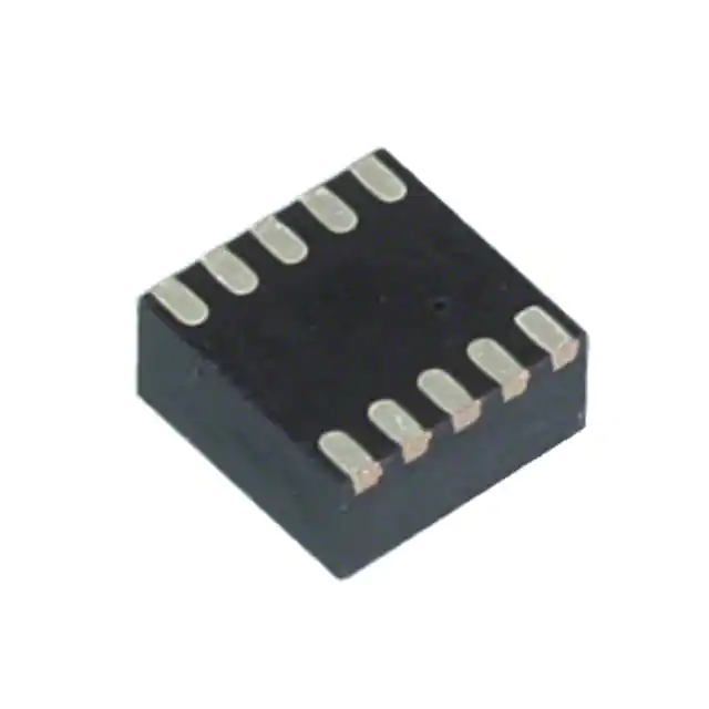
- Part No.:
- MAG3110FCR1
- Manufacturer:
- NXP Semiconductors
- Category:
- Linear, Compass (ICs)
- Package:
- 10-VFDFN
- Datasheet:
-
 MAG3110FCR1.pdf
- Description:
- SENSOR MR I2C 10DFN
- Quantity:
- Payment:

- Shipping:

Inventory:4,363
Please send an inquiry. Send us your inquiry, and we will respond immediately.
Product details
Overview
MAG3110FCR1 from Freescale Semiconductor is a digital 3-axis magnetometer IC designed for electronic compass applications, delivering ±1000 µT full-scale range, 0.10 µT/LSB sensitivity, and I²C interface at up to 400 kHz with 80 Hz output data rate. It operates from 1.95 V to 3.6 V supply and supports -40°C to +85°C industrial temperature range.
For engineers reviewing the MAG3110FCR1 datasheet, MAG3110FCR1 pinout, MAG3110FCR1 application, or MAG3110FCR1 equivalent, this device serves as a low-power, factory-calibrated magnetic field sensor enabling heading calculation when fused with accelerometer data in portable and embedded navigation systems.
Technical Context
The MAG3110FCR1 integrates a magnetic transducer and ASIC with on-chip digital signal processing, supporting both continuous and triggered measurement modes via CTRL_REG1 configuration. Its internal auto-magnetic reset (AUTO_MRST_EN) and user offset correction registers (OFF_X/Y/Z) enable hard-iron compensation without external calibration firmware.
It implements a 16-bit two's complement output format across X/Y/Z axes, with configurable oversampling ratios (OSR = 00–11) directly trading noise floor (0.25–0.4 µT rms) against current consumption (8.6–900 µA) and bandwidth (0.63–80 Hz). The I²C interface complies with Fast Mode (400 kHz) and supports clock stretching.
Key Specifications
| Parameter | Value and Actual Design Meaning |
|---|---|
| Full-scale range | ±1000 µT - enables detection of Earth's geomagnetic field (25–65 µT) with >15-bit effective resolution |
| Sensitivity | 0.10 µT/LSB - maps raw 16-bit output to physical field strength with deterministic scaling |
| Output data rate | Up to 80 Hz - supports real-time orientation updates in dynamic handheld devices |
| Supply voltage (VDD) | 1.95 V to 3.6 V - compatible with single-cell Li-ion and 3.3 V logic rails |
| Interface | I²C Fast Mode (400 kHz) - enables high-speed register access with minimal MCU overhead |
| Operating temperature | -40°C to +85°C - qualified for automotive cabin and industrial outdoor deployment |
| Current consumption | 2 µA standby / 900 µA active (80 Hz, OS=00) - extends battery life in always-on sensing nodes |
Pinout & Package
Package: 10-pin DFN (2 mm × 2 mm × 0.85 mm, 0.4 mm pitch), case 2154-02, RoHS compliant.
| Pin/Terminal | Circuit Role | Design Meaning |
|---|---|---|
| 1 - Cap-A | Bypass capacitor connection for internal regulator | Stabilizes analog core voltage; requires 100 nF ceramic capacitor placed adjacent to pin |
| 2 - VDD | Main power supply input | Supplies analog and digital core; decoupled with 100 nF + 1 µF capacitors per layout guidelines |
| 3 - NC | No connect | Must remain unconnected; no internal bonding or function |
| 4 - Cap-R | Magnetic reset pulse capacitor terminal | Connects external capacitor to enable automatic magnetic domain reset for stable zero-flux baseline |
| 5 - GND | Analog ground reference | Primary return path for magnetic sensor and ADC; tied to system ground plane |
| 6 - SDA | I²C serial data line | Open-drain bidirectional bus; requires pullup to VDDIO (typically 4.7 kΩ) |
| 7 - SCL | I²C serial clock line | Open-drain clock input; synchronized with SDA for register read/write transactions |
| 8 - VDDIO | Digital I/O supply | Defines logic thresholds for SDA/SCL/INT1; range 1.62 V to VDD |
| 9 - INT1 | Data-ready interrupt output | Active-high open-drain signal asserted when new X/Y/Z data is available in registers |
| 10 - GND | Digital ground reference | Return path for I/O circuitry; recommended to tie to same ground plane as Pin 5 |
Key Features
| Feature | Design Value |
|---|---|
| Factory-calibrated sensitivity & tempco | Eliminates need for end-user gain/offset calibration; coefficients applied automatically before register update |
| User offset correction registers (X/Y/Z) | Enables board-level hard-iron compensation via OFF_X/Y/Z registers without modifying firmware math |
| Low-power triggered measurement mode | Reduces average current by entering STANDBY after single acquisition-ideal for event-driven wake-up systems |
| Auto-magnetic reset (AUTO_MRST_EN) | Prevents magnetic domain drift during long-term operation; maintains zero-flux accuracy over time and temperature |
| Interrupt-driven data synchronization | INT1 assertion eliminates polling overhead and ensures deterministic timing for sensor fusion algorithms |
Applications
| Smartphone Electronic Compass | Personal Navigation Device (PND) |
|---|---|
Use Scenario: Real-time heading calculation during pedestrian navigation in urban canyons where GPS signal is obstructed. IC Role / Device Role / Timing Role: Magnetometer providing 3-axis magnetic field vector sampled at 20–40 Hz, fused with accelerometer and gyroscope data for tilt-compensated compass output. Use Value: Enables accurate directional awareness independent of satellite visibility, leveraging MAG3110FCR1's ±1000 µT range and 0.10 µT/LSB resolution to resolve subtle field variations. |
Use Scenario: Turn-by-turn guidance in automotive-grade portable navigation units requiring robust magnetic sensing under varying thermal conditions. IC Role / Device Role / Timing Role: Primary magnetic field sensor operating in continuous ACTIVE mode at 10 Hz ODR, with factory calibration ensuring consistent heading accuracy across -40°C to +85°C. Use Value: Delivers stable compass performance without recalibration, supported by MAG3110FCR1's auto-magnetic reset and ±0.1 %/°C sensitivity tempco. |
| UAV Attitude Stabilization | Wrist-Worn Fitness Tracker |
Use Scenario: Supplementing IMU-based attitude estimation in quadcopters during low-G maneuvers where gyro drift accumulates. IC Role / Device Role / Timing Role: Low-noise (0.25 µT rms) magnetometer supplying absolute yaw reference at 80 Hz, synchronized via INT1 to minimize latency in control loop. Use Value: Improves long-duration heading stability using MAG3110FCR1's oversampling capability and embedded digital filtering-critical for autonomous flight safety. |
Use Scenario: Step-count and activity classification in compact wearable devices constrained by battery capacity and PCB area. IC Role / Device Role / Timing Role: Ultra-low-power magnetometer operating in triggered mode (2 µA standby), activated only during periodic orientation checks to conserve energy. Use Value: Extends battery life beyond 7 days while maintaining compass functionality, enabled by MAG3110FCR1's sub-µA standby current and fast wake-up (<25 ms). |
Equivalent & Alternatives
The following parts are listed as comparable options for similar 3-axis digital magnetometer applications.
| Alternative Part | Technical Difference | Application Difference | Selection Advice |
|---|---|---|---|
| AKM AK8963 | Higher sensitivity (0.15 µT/LSB), wider ODR range (up to 100 Hz), but requires external biasing and lacks integrated magnetic reset | Used in premium smartphones with advanced sensor fusion stacks; demands more complex calibration and layout | Select AK8963 only if higher bandwidth and sensitivity justify added design complexity and cost |
| STMicroelectronics LIS3MDL | Wider full-scale range (±16 Gauss = ±1600 µT), lower noise (0.15 µT rms), SPI/I²C dual interface, but larger 12-pin LGA package | Preferred in industrial IoT gateways needing extended field tolerance and multi-interface flexibility | Choose LIS3MDL when system requires >±1000 µT headroom or SPI compatibility; MAG3110FCR1 remains optimal for space-constrained DFN designs |
Compared with AK8963 and LIS3MDL, MAG3110FCR1 offers the smallest footprint (2×2 mm DFN), lowest standby current (2 µA), and integrated magnetic reset-making it uniquely suited for ultra-compact, battery-sensitive e-compass implementations where layout simplicity and long-term baseline stability are critical.
Availability
MAG3110FCR1 is available at Aetrix Electronics and suitable for smartphone compass modules, personal navigation devices, UAV stabilization subsystems, and wrist-worn fitness trackers requiring stable component supply across production lifecycles.
Supply support for MAG3110FCR1 includes scheduled delivery planning, volume procurement assistance, BOM continuity management, traceable sourcing, and lifecycle availability coordination for OEM customers, industrial embedded developers, connected-device designers, and electronics production programs.
Manufacturer
Freescale Semiconductor (now part of NXP Semiconductors) is a global leader in embedded processing and sensor solutions, specializing in automotive, industrial, and consumer microcontrollers and intelligent sensors.
The MAG3110FCR1 belongs to Freescale's Xtrinsic sensor family, engineered specifically for low-power, high-accuracy orientation sensing in mobile and wearable electronics-emphasizing factory calibration, small form factor, and seamless I²C integration.
FAQ
What is the I²C slave address of the MAG3110FCR1?
The MAG3110FCR1 uses a fixed 7-bit I²C slave address of 0x0E (0b0001110) in standard notation. This address is hard-coded and cannot be modified. When communicating, the full 8-bit address byte sent by the master includes this 7-bit value plus the R/W bit (0 for write, 1 for read). The FXMS3110CDR1 variant uses 0x0F, confirming MAG3110FCR1's distinct addressing for multi-sensor I²C bus configurations.
Does the MAG3110FCR1 require external calibration for basic compass operation?
No, the MAG3110FCR1 does not require external calibration for basic compass operation because it includes factory calibration for sensitivity and temperature coefficient of sensitivity. These coefficients are automatically applied by the internal ASIC before writing data to output registers (0x01–0x06). However, user offset correction (via OFF_X/Y/Z registers) is recommended to compensate for board-level hard-iron effects-this is optional but improves heading accuracy in final assembly.
How does the MAG3110FCR1 handle magnetic interference from nearby components?
The MAG3110FCR1 mitigates magnetic interference through its integrated auto-magnetic reset (AUTO_MRST_EN) function, which applies controlled reset pulses to clear residual magnetic domains in the sensor die. Combined with user offset correction registers and factory-trimmed zero-flux offset (±100 µT), this allows stable baseline recovery even after exposure to moderate stray fields. Layout best practices-such as keeping Cap-R ≥100 nF and avoiding placement near motors or inductors-remain essential for optimal MAG3110FCR1 performance.
What is the fastest achievable output data rate for the MAG3110FCR1, and what trade-offs apply?
The MAG3110FCR1 achieves a maximum output data rate (ODR) of 80 Hz in ACTIVE mode with oversampling ratio (OSR) set to 00. At this setting, noise is 0.4 µT rms and supply current is 900 µA. Increasing OSR reduces noise (down to 0.25 µT rms at OSR=11) but lowers ODR proportionally-for example, OSR=11 limits ODR to 20 Hz. Thus, 80 Hz represents the peak speed/noise/current operating point, ideal for real-time motion tracking where latency matters most.
Can the MAG3110FCR1 operate with different VDD and VDDIO voltages?
Yes, the MAG3110FCR1 supports independent supply domains: VDD (1.95–3.6 V) powers the analog core and magnetic transducer, while VDDIO (1.62 V to VDD) sets logic thresholds for SDA, SCL, and INT1. This allows interfacing with 1.8 V I/O systems while running the sensor core at 2.4 V for optimal noise performance-or using 3.3 V VDD with 1.8 V VDDIO to match legacy MCU interfaces. Input voltage on SCL/SDA must not exceed VDDIO + 0.3 V.
MAG3110FCR1 Specifications
- Product attributes
- Attribute value
- Manufacturer:
- NXP Semiconductors
- Series:
- -
- Package/Case:
- 10-VFDFN
- Packaging:
- Tape & Reel (TR)
- Product Status:
- Obsolete
- Technology:
- Magnetoresistive
- Axis:
- X, Y, Z
- Output Type:
- I2C
- Sensing Range:
- ±1mT
- Voltage - Supply:
- 1.9V ~ 3.6V
- Current - Supply (Max):
- 900µA (Typ)
- Current - Output (Max):
- -
- Resolution:
- -
- Bandwidth:
- -
- Operating Temperature:
- -40°C ~ 85°C
- Grade:
- -
- Qualification:
- -
- Features:
- Temperature Compensated
- Supplier Device Package:
- 10-DFN (2x2)
- Mounting Type:
- Surface Mount
MAG3110FCR1 FAQ
1.How can I place an order for MAG3110FCR1 through Aetrix?
Please submit a Request for Quotation (RFQ) for MAG3110FCR1 on Aetrix. Our sales agent will provide a competitive quotation and guide you through the order confirmation once you accept the terms.
2.Are the price and stock information for MAG3110FCR1 reliable?
The price and inventory of MAG3110FCR1 are updated periodically and may fluctuate due to market conditions. Stock and pricing data are typically refreshed every 24 hours. Quotation validity for MAG3110FCR1 is usually 5 days.
3.What payment methods are accepted for MAG3110FCR1?
We accept Wire Transfer, PayPal, Credit Card, Western Union, MoneyGram, and Escrow for MAG3110FCR1 transactions.
Note: Certain payment methods may incur a processing fee.
4.How is shipping managed for MAG3110FCR1?
MAG3110FCR1 orders can be shipped via leading logistics carriers, including DHL, UPS, FedEx, TNT, or Registered Mail.
Once your MAG3110FCR1 order is processed, you will receive an email with the shipment details and tracking number.
Note: Tracking information may take up to 24 hours to appear. Express delivery typically takes 3–5 business days.
5.How can I obtain technical support or documentation for MAG3110FCR1?
For technical support, including MAG3110FCR1 datasheets, pinout diagrams, or application guidance, please contact our engineering support team. They can provide detailed documentation and assistance for your MAG3110FCR1 requirements.
6.How does Aetrix verify that MAG3110FCR1 is sourced from the original manufacturer or authorized distributors?
All MAG3110FCR1 products on Aetrix are procured from qualified distributors and authorized channels. Our dedicated quality assurance team conducts strict verification, including traceability checks and, if necessary, third-party testing. This ensures that MAG3110FCR1 meets industry standards.
7.What is the process for return or replacement of MAG3110FCR1?
All MAG3110FCR1 units undergo pre-shipment inspection (PSI). If there is an issue with MAG3110FCR1, returns or replacements are accepted under the following conditions:
1.Quantity discrepancies, incorrect items, or visible external defects (such as breakage or corrosion), acknowledged by Aetrix.
2.The issue is reported within 90 days of delivery.
3.The MAG3110FCR1 part is unused and in its original packaging.
Return procedure for MAG3110FCR1:
1.Submit a request within 90 days.
2.Obtain a Return Material Authorization (RMA) from Aetrix.
MAG3110FCR1 Tags
-
DRV5053VAQDBZR
Texas Instruments
-
MMC5603NJ
Memsic Inc.

-
DRV5055A1QDBZR
Texas Instruments
-
MLX90392ELQ-AAA-011-RE
Melexis Technologies NV

-
CT100LW-HS6
Allegro MicroSystems
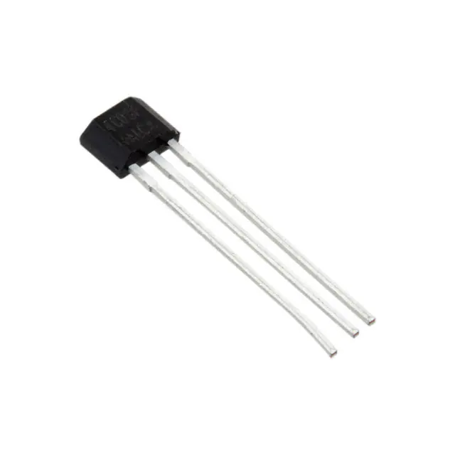
-
DRV5056A1ELPGMQ1
Texas Instruments
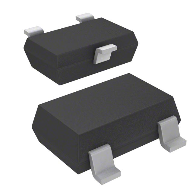
-
A1304ELHLX-T
Allegro MicroSystems
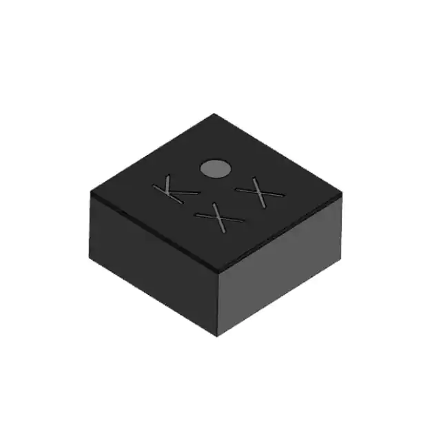
-
MMC5633NJL
Memsic Inc.
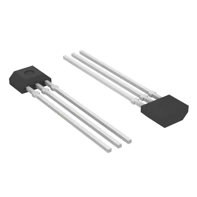
-
A1308KUA-2-T
Allegro MicroSystems
-
A1308KUA-1-T
Allegro MicroSystems
-
SI7210-B-04-IVR
Silicon Labs
-
A1308LLHLT-2-T
Allegro MicroSystems
Tech Hub

A practical engineering guide to 3.3V and 5V logic compatibility, input thresholds, resistor dividers, translator ICs, MOSFET level shifting, I2C pull-ups, timing limits and power-sequencing risks.

The 74HC595 uses push-pull logic outputs, while the TPIC6B595 uses 50 V open-drain DMOS sinks for higher-power loads. This guide compares timing, current limits, 3.3 V interfacing, load wiring, thermal…

The 74HC595 converts serial data into eight stable parallel outputs. This guide covers pin functions, shift and storage timing, OE and MR behavior, drive-current limits, cascading, voltage compatibilit…

A technical comparison of level-sensitive latches and edge-triggered flip-flops, covering timing windows, setup and hold limits, master–slave operation, time borrowing, race-through, HDL inference and…

A D latch stores one bit while Enable controls when data can pass. This reference covers gate-level operation, truth tables, transparency, setup and hold timing, LE versus OE, common ICs and practical …

An SR latch stores one bit through cross-coupled feedback. This engineering reference covers NOR and NAND implementations, truth tables, forbidden-state recovery, gated operation, switch debouncing, fa…

Latch circuits retain one bit through feedback. This technical reference covers SR and D latches, truth tables, transparency, timing limits, latch-versus-flip-flop behavior, applications and common log…

An engineering guide to LED driver operation, constant-current and constant-voltage outputs, linear and switching topologies, dimming, IC selection, calculations, replacement compatibility, and fault c…

Operational amplifier guide covering op amp basics, feedback, ideal vs real op amps, common configurations, buffer circuits, offset, bias current, gain-bandwidth, slew rate, rail-to-rail limits and sel…

Jumper cables guide covering safe connection order, red and black clamp placement, final ground connection, cable gauge, length, clamp quality, copper vs CCA cables, jump starter comparison and battery…


