
 My Inquiry
 My Account


Analog Devices Inc./Maxim Integrated MAX11068GUU+
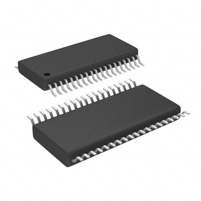
- Part No.:
- MAX11068GUU+
- Manufacturer:
- Analog Devices Inc./Maxim Integrated
- Category:
- Battery Management
- Package:
- 38-TFSOP (0.173", 4.40mm Width)
- Datasheet:
-
 MAX11068GUU+.pdf
- Description:
- IC BAT MON MULT-CHEM 12C 38TSSOP
- Quantity:
- Payment:

- Shipping:

Inventory:1,274
Please send an inquiry. Send us your inquiry, and we will respond immediately.
Product details
Overview
MAX11068GUU+ from Maxim Integrated is a programmable, 12-channel, high-voltage smart data-acquisition interface IC optimized for battery monitoring in automotive and HEV/EV battery packs. It performs differential cell voltage measurement (0.5V–4.7V full-accuracy range), integrates 12 cell-balancing switches (200mA), a 12-bit SAR ADC (<107µs for all 12 cells), and dual I²C/SMBus ladder ports with level shifting. It operates across –40°C to +105°C (AEC-Q100 Grade 2) and supports up to 31 daisy-chained modules.
For engineers reviewing the MAX11068GUU+ datasheet, MAX11068GUU+ pinout, MAX11068GUU+ application, or MAX11068GUU+ equivalent, this page delivers verified technical context, real-world timing and accuracy specs, validated SMBus ladder interoperability, and precise thermal/fault-detection behavior - critical for high-reliability battery management system (BMS) design and qualification.
Technical Context
The MAX11068GUU+ implements a two-phase acquisition architecture: first, simultaneous differential sampling of all 12 cell voltages via a high-voltage mux; second, ADC input chopping to cancel offset/gain drift and noise-induced errors. Its internal 6.0MHz oscillator (±3.0%) clocks the SAR ADC and state machine, while a separate 32.768kHz oscillator enables alarm heartbeat timing.
It features dual isolated I²C domains: lower port (SCLL/SDAL/ALRML, referenced to GNDL/VDDL) interfaces with host or lower modules; upper port (SCLU/SDAU/ALRMU, referenced to GNDU/VDDU) communicates with higher modules in stacked architectures. Level-shifted communication eliminates external isolators and supports up to 31 devices on one SMBus ladder with autoaddressing and CRC-protected commands.
Key Specifications
| Parameter | Value and Actual Design Meaning |
|---|---|
| Cell channels | 12 independent differential inputs (C0–C12), enabling full-stack monitoring of series-connected Li-ion/NiMH/SuperCap cells. |
| Measurement accuracy | ±20mV over –40°C to +105°C (–40°C to +105°C, 3.0V cell), supporting AEC-Q100 Grade 2 BMS compliance. |
| ADC resolution & speed | 12-bit SAR ADC; completes all 12-cell conversion in <107µs - sufficient for real-time balancing control loops. |
| Cell balancing | 12 integrated MOSFET switches; each supports 200mA discharge current and open-wire fault detection. |
| Supply & regulation | Integrated 6V–70V linear regulator (VAA = 3.4V ±50mV); 25ppm/°C 2.5V reference (REF) for ratiometric AUXIN/THRM measurements. |
| Communication | Dual level-shifted SMBus/I²C ports (upper/lower); supports up to 31 daisy-chained devices with hardware handshake and CRC error checking. |
| Power modes | 2.0mA active, 75µA standby, <1µA shutdown - enabling low-quiescent operation in always-on BMS monitoring. |
Pinout & Package
MAX11068GUU+ is housed in a lead-free, RoHS-compliant 38-pin TSSOP package (9.7mm × 4.4mm × 1.0mm), qualified per AEC-Q100 Grade 2 (–40°C to +105°C).
| Pin/Terminal | Circuit Role | Design Meaning |
|---|---|---|
| DCIN (Pin 1) | High-voltage power input | Accepts 6V–70V supply; powers internal LDO (VAA) and charge pump; requires 1µF bypass to GND. |
| C0–C12 (Pins 25–37) | Differential cell voltage inputs | Form Kelvin connections across 12 series cells; C0 = cell 1(–), C12 = top-of-stack (+); all measured differentially. |
| VDDU/GNDU (Pins 4/5) | Upper I²C domain supply/ground | Level-shifted domain for communicating with higher modules; VDDU generated by internal charge pump (~3.4V above DCIN). |
| SCLU/SDAU/ALRMU (Pins 6/7/8) | Upper I²C clock/data/alarm | Swing between VDDU/GNDU; enable laddered communication without optocouplers or isolators. |
| VDDL/GNDL (Pins 13/14) | Lower I²C domain supply/ground | Interface domain for host or lower modules; VDDL tied to VAA; GNDL star-connected to AGND. |
| SCLL/SDAL/ALRML (Pins 15/16/17) | Lower I²C clock/data/alarm | Swing between VDDL/GNDL; ALRML provides 16kHz heartbeat (no alarm) or logic-high latch (alarm active). |
| SHDN (Pin 18) | Active-low shutdown control | 60V-tolerant input; asserts full device shutdown (regulators, oscillators, ADC off); used for module-level reset or cascade control. |
| AUXIN1/AUXIN2/THRM (Pins 19/20/21) | Temperature sensing interface | AUXIN1/2 accept 0–VAA ratiometric inputs; THRM supplies switched +3.4V bias to NTC thermistors for accurate temperature measurement. |
Key Features
| Feature | Design Value |
|---|---|
| Dual-domain SMBus ladder interface | Enables scalable BMS stacks up to 372 cells (31 × 12) with deterministic command propagation delay (≤30µs max for full stack). |
| Two-phase error-cancelling ADC acquisition | First phase acquires all 12 cell voltages; second phase chops ADC input to eliminate offset drift and noise coupling - ensuring ±0.25% accuracy over temperature. |
| Integrated cell-equalization switches | 12 on-chip MOSFETs support 200mA discharge per cell; also detect open-circuit sense-line faults during balancing activation. |
| On-die thermal protection | Internal sensor triggers automatic disable of regulators and balancing switches at +145°C junction temperature, with 15°C hysteresis. |
| Ratiometric auxiliary measurement | AUXIN1/AUXIN2 + THRM enable direct NTC thermistor readout using VAA as reference - eliminating external reference dependency and improving temperature accuracy. |
Applications
| Electric Vehicle Battery Pack Monitoring | Hybrid Electric Vehicle (HEV) BMS |
|---|---|
Use Scenario: Real-time voltage, temperature, and fault monitoring across 12-series Li-ion cells in traction battery modules. IC Role / Device Role / Timing Role: Primary cell-sensing and balancing controller; performs full 12-cell acquisition in <107µs and executes balancing decisions within same cycle. Use Value: Enables precise state-of-charge (SoC) and state-of-health (SoH) estimation under dynamic load and wide temperature range (–40°C to +105°C). |
Use Scenario: Distributed monitoring of high-voltage battery stacks in regenerative braking and engine-start systems. IC Role / Device Role / Timing Role: Smart analog front-end with SMBus ladder interface; relays host commands across multiple modules with ≤1µs inter-device latency. Use Value: Eliminates need for external isolators or level shifters, reducing BOM cost and PCB area in multi-module HEV battery systems. |
| High-Power Backup Systems | Industrial Energy Storage Modules |
Use Scenario: Voltage balancing and overvoltage/undervoltage protection in 48V–700V telecom or UPS battery banks. IC Role / Device Role / Timing Role: Fault-detection engine with digital thresholds (OV/UV/OT/UT) and latched ALRM outputs for system-level shutdown coordination. Use Value: Provides autonomous cell-level protection independent of host MCU - critical for fail-safe operation during grid outage or overload events. |
Use Scenario: Modular energy storage units deployed in microgrids or renewable integration, requiring field-upgradable BMS nodes. IC Role / Device Role / Timing Role: Scalable data-acquisition node with autoaddressing SMBus ladder; supports hot-plug addition/removal of modules without firmware reconfiguration. Use Value: Enables flexible capacity expansion and maintenance without redesigning communication infrastructure or recalibrating host software. |
Availability
MAX11068GUU+ is available at Aetrix Electronics and suitable for electric vehicle battery pack monitoring, hybrid electric vehicle BMS, and high-power backup systems requiring stable component supply, AEC-Q100 Grade 2 qualification, and long-term lifecycle support.
Supply support for MAX11068GUU+ includes scheduled delivery planning, volume procurement assistance, BOM continuity management, traceable sourcing, and lifecycle availability coordination for OEM customers, industrial embedded developers, connected-device designers, and electronics production programs.
Manufacturer
Maxim Integrated (now part of Analog Devices) is a semiconductor company specializing in precision analog, mixed-signal, and power-management solutions for automotive, industrial, and communications applications.
The MAX11068GUU+ belongs to Maxim's battery sensor product line, designed specifically for high-reliability, high-voltage battery management in automotive-grade and industrial energy storage systems - emphasizing accuracy, fault resilience, and scalable daisy-chain architecture.
FAQ
What is the maximum number of MAX11068GUU+ devices that can be daisy-chained on a single SMBus ladder?
The MAX11068GUU+ supports up to 31 devices on one SMBus ladder using its level-shifted upper/lower I²C ports and autoaddressing protocol. This allows monitoring of up to 372 cells (31 × 12) with bounded command propagation delay - 30µs maximum for full-stack response - making it suitable for large-format EV battery packs and industrial ESS systems where scalability is essential. Each MAX11068GUU+ handles local acquisition while relaying commands transparently.
How does the MAX11068GUU+ achieve ±0.25% voltage measurement accuracy over temperature?
The MAX11068GUU+ achieves ±0.25% accuracy through a two-phase acquisition method: first, simultaneous sampling of all 12 cell voltages; second, ADC input chopping to cancel offset and gain drift. Combined with factory calibration at +25°C and a 25ppm/°C internal 2.5V reference, this architecture maintains tight tolerance across –40°C to +105°C - critical for SoC estimation in automotive BMS. The MAX11068GUU+ specifies ±20mV absolute error over full temperature range at 3.0V cell voltage.
Can the MAX11068GUU+ monitor temperature without external components?
Yes - the MAX11068GUU+ integrates THRM (switched +3.4V bias), AUXIN1, and AUXIN2 to form a complete ratiometric temperature measurement path. When paired with an external NTC thermistor and simple resistor divider, it delivers calibrated temperature readings using VAA as reference - no external reference or op-amp required. The MAX11068GUU+ also includes on-die thermal sensing that disables balancing and regulators above +145°C junction temperature.
What is the role of the HV pin on the MAX11068GUU+?
The HV pin on the MAX11068GUU+ is a high-voltage bias node internally connected to the charge pump. It supplies operating voltage to the high-voltage multiplexer and must be decoupled to AGND with a 3.3µF capacitor. Unlike DCIN, HV is not a power input but a stabilized internal rail - critical for maintaining mux linearity and common-mode rejection across the full 0.7V–7.0V input common-mode range specified for C1–C12 pins.
Does the MAX11068GUU+ support both overvoltage and undervoltage fault detection per cell?
Yes - the MAX11068GUU+ includes programmable digital thresholds for per-cell overvoltage (OV) and undervoltage (UV) detection, plus open-circuit sense-line detection and high/low temperature alarms. Detected faults trigger latched ALRML/ALRMU outputs and are reported via SMBus registers. These functions operate autonomously without host intervention, enabling fail-safe BMS responses even during host processor reset or communication loss - a core requirement for ISO 26262 ASIL-B/C designs.
MAX11068GUU+ Specifications
- Product attributes
- Attribute value
- Manufacturer:
- Analog Devices Inc./Maxim Integrated
- Series:
- -
- Package/Case:
- 38-TFSOP (0.173", 4.40mm Width)
- Packaging:
- Tube
- Product Status:
- Active
- Function:
- Battery Monitor
- Battery Chemistry:
- Multi-Chemistry
- Number of Cells:
- 12
- Fault Protection:
- Over Temperature, Over/Under Voltage
- Interface:
- I2C
- Operating Temperature:
- -40°C ~ 105°C (TA)
- Grade:
- Automotive
- Qualification:
- AEC-Q100
- Mounting Type:
- Surface Mount
- Supplier Device Package:
- 38-TSSOP
MAX11068GUU+ FAQ
1.How can I place an order for MAX11068GUU+ through Aetrix?
Please submit a Request for Quotation (RFQ) for MAX11068GUU+ on Aetrix. Our sales agent will provide a competitive quotation and guide you through the order confirmation once you accept the terms.
2.Are the price and stock information for MAX11068GUU+ reliable?
The price and inventory of MAX11068GUU+ are updated periodically and may fluctuate due to market conditions. Stock and pricing data are typically refreshed every 24 hours. Quotation validity for MAX11068GUU+ is usually 5 days.
3.What payment methods are accepted for MAX11068GUU+?
We accept Wire Transfer, PayPal, Credit Card, Western Union, MoneyGram, and Escrow for MAX11068GUU+ transactions.
Note: Certain payment methods may incur a processing fee.
4.How is shipping managed for MAX11068GUU+?
MAX11068GUU+ orders can be shipped via leading logistics carriers, including DHL, UPS, FedEx, TNT, or Registered Mail.
Once your MAX11068GUU+ order is processed, you will receive an email with the shipment details and tracking number.
Note: Tracking information may take up to 24 hours to appear. Express delivery typically takes 3–5 business days.
5.How can I obtain technical support or documentation for MAX11068GUU+?
For technical support, including MAX11068GUU+ datasheets, pinout diagrams, or application guidance, please contact our engineering support team. They can provide detailed documentation and assistance for your MAX11068GUU+ requirements.
6.How does Aetrix verify that MAX11068GUU+ is sourced from the original manufacturer or authorized distributors?
All MAX11068GUU+ products on Aetrix are procured from qualified distributors and authorized channels. Our dedicated quality assurance team conducts strict verification, including traceability checks and, if necessary, third-party testing. This ensures that MAX11068GUU+ meets industry standards.
7.What is the process for return or replacement of MAX11068GUU+?
All MAX11068GUU+ units undergo pre-shipment inspection (PSI). If there is an issue with MAX11068GUU+, returns or replacements are accepted under the following conditions:
1.Quantity discrepancies, incorrect items, or visible external defects (such as breakage or corrosion), acknowledged by Aetrix.
2.The issue is reported within 90 days of delivery.
3.The MAX11068GUU+ part is unused and in its original packaging.
Return procedure for MAX11068GUU+:
1.Submit a request within 90 days.
2.Obtain a Return Material Authorization (RMA) from Aetrix.
MAX11068GUU+ Tags

-
BQ29700DSER
Texas Instruments

-
S-8241ABKMC-GBKT2G
ABLIC Inc.
-
S-8241ABPMC-GBPT2G
ABLIC Inc.

-
BQ27427YZFR
Texas Instruments

-
BQ27426YZFR
Texas Instruments

-
STC3117IJT
STMicroelectronics

-
STC3115IJT
STMicroelectronics

-
BQ76925RGER
Texas Instruments
-
NPM1100-QDAA-R
Nordic Semiconductor ASA

-
BQ27441DRZR-G1A
Texas Instruments

-
STC3115AIQT
STMicroelectronics

-
S-8252AAL-M6T1U
ABLIC Inc.
Tech Hub

A practical engineering guide to 3.3V and 5V logic compatibility, input thresholds, resistor dividers, translator ICs, MOSFET level shifting, I2C pull-ups, timing limits and power-sequencing risks.

The 74HC595 uses push-pull logic outputs, while the TPIC6B595 uses 50 V open-drain DMOS sinks for higher-power loads. This guide compares timing, current limits, 3.3 V interfacing, load wiring, thermal…

The 74HC595 converts serial data into eight stable parallel outputs. This guide covers pin functions, shift and storage timing, OE and MR behavior, drive-current limits, cascading, voltage compatibilit…

A technical comparison of level-sensitive latches and edge-triggered flip-flops, covering timing windows, setup and hold limits, master–slave operation, time borrowing, race-through, HDL inference and…

A D latch stores one bit while Enable controls when data can pass. This reference covers gate-level operation, truth tables, transparency, setup and hold timing, LE versus OE, common ICs and practical …

An SR latch stores one bit through cross-coupled feedback. This engineering reference covers NOR and NAND implementations, truth tables, forbidden-state recovery, gated operation, switch debouncing, fa…

Latch circuits retain one bit through feedback. This technical reference covers SR and D latches, truth tables, transparency, timing limits, latch-versus-flip-flop behavior, applications and common log…

An engineering guide to LED driver operation, constant-current and constant-voltage outputs, linear and switching topologies, dimming, IC selection, calculations, replacement compatibility, and fault c…

Operational amplifier guide covering op amp basics, feedback, ideal vs real op amps, common configurations, buffer circuits, offset, bias current, gain-bandwidth, slew rate, rail-to-rail limits and sel…

Jumper cables guide covering safe connection order, red and black clamp placement, final ground connection, cable gauge, length, clamp quality, copper vs CCA cables, jump starter comparison and battery…


