
 My Inquiry
 My Account


Analog Devices Inc./Maxim Integrated MAX11081GUU+
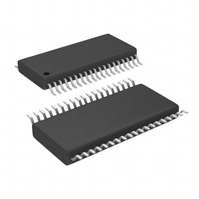
- Part No.:
- MAX11081GUU+
- Manufacturer:
- Analog Devices Inc./Maxim Integrated
- Category:
- Battery Management
- Package:
- 38-TFSOP (0.173", 4.40mm Width)
- Datasheet:
-
 MAX11081GUU+.pdf
- Description:
- IC BATT MON LI-ION 1-12C 38TSSOP
- Quantity:
- Payment:

- Shipping:

Inventory:3,356
Please send an inquiry. Send us your inquiry, and we will respond immediately.
Product details
Overview
MAX11081GUU+ from Maxim Integrated is a 12-channel, high-voltage battery-pack fault monitor IC designed for Li+ multicell stacks up to 72V. It provides pin-selectable overvoltage detection (3.3V–4.8V, ±25mV accuracy) and undervoltage detection (1.6V–2.8V, ±100mV accuracy), with programmable delay (3.0ms–3.32s) and 37.5mV comparator hysteresis. It operates in automotive-grade temperature range (−40°C to +105°C) and supports daisy-chained fault propagation in EV battery management systems.
For engineers reviewing the MAX11081GUU+ datasheet, MAX11081GUU+ pinout, MAX11081GUU+ application, or MAX11081GUU+ equivalent, this page delivers verified specifications, validated daisy-chain interface behavior, confirmed TSSOP-38 package mapping, and real-world fault-monitoring use cases - all grounded in Maxim's official documentation and electrical characterization data.
Technical Context
The MAX11081GUU+ implements differential cell monitoring across 12 Li+ cells using internal level-shifting and attenuation (×0.25) to reference all inputs to AGND. Its fault logic triggers only after sustained threshold violation beyond user-programmed CDLY capacitor delay, with built-in hysteresis (37.5mV) preventing chatter during marginal voltage transitions.
Daisy-chain operation relies on dual-level signaling: ALRML (VAA-referenced, 4.096kHz heartbeat) propagates downward, while ALRMU (GNDU-referenced) receives alarm status from upper modules via 3.3nF/150kΩ coupling. The integrated charge pump (CP+/CP−) generates VDDU above DCIN to enable level-shifted inter-module communication without optoisolators.
Key Specifications
| Parameter | Value and Actual Design Meaning |
|---|---|
| Cell Monitoring Channels | 12 independent differential inputs (C0–C12), supporting up to 12-series Li+ cells in stacked battery packs. |
| Overvoltage Threshold Range | +3.3V to +4.8V in 100mV steps, with ±25mV guaranteed accuracy over −40°C to +105°C - enables precise cell balancing guardbanding. |
| Undervoltage Threshold Range | +1.6V to +2.8V in 200mV steps, ±100mV accuracy; configurable disable via UVSEL0–UVSEL2 pins - supports deep-discharge protection or low-power sleep modes. |
| Comparator Hysteresis | 37.5mV (MAX11081-specific), preventing false alarms during slow voltage recovery or noise-induced threshold crossings. |
| Alarm Delay Programmability | 3.0ms to 3.32s via external CDLY capacitor (15nF–16.5µF ceramic), enabling design-tailored response to transient vs. persistent faults. |
| Supply Voltage Range | DCIN = +6.0V to +72V; internal 3.3V linear regulator (VAA) powers analog/digital circuitry - eliminates need for external bias supply in HV battery systems. |
| Operating Temperature | −40°C to +105°C, AEC-Q100 Type 2 qualified - validated for under-hood and traction-battery environments in EV/HEV applications. |
| Quiescent Current | 80µA in operating mode; 2µA in shutdown (SHDN = low) - extends standby life in always-on BMS monitoring nodes. |
Pinout & Package
MAX11081GUU+ is housed in a lead-free, RoHS-compliant 38-pin TSSOP package (9.7mm × 4.4mm, 0.5mm pitch), optimized for high-density battery module PCB layouts.
| Pin | Circuit Role | Design Meaning |
|---|---|---|
| DCIN (1) | High-voltage input supply | Accepts +6.0V to +72V stack voltage; powers internal 3.3V regulator (VAA) and charge pump - no external DC-DC required. |
| C0–C12 (4–16) | Differential cell voltage inputs | C0 = cell 1 minus; C12 = cell 12 plus; each adjacent pair (e.g., C1/C0) measures one cell - supports direct connection to series-connected Li+ cells. |
| OVSEL0–OVSEL3 (20–23) | Overvoltage threshold select | 4-bit binary input selecting one of 16 thresholds (3.3V–4.8V); internal pulldowns allow AGND/VAA tie-off - eliminates need for external logic. |
| UVSEL0–UVSEL2 (17–19) | Undervoltage threshold select | 3-bit input selecting one of eight thresholds (1.6V–2.8V) or disable state (000) - enables flexible low-voltage cutoff per application requirements. |
| CD (28) | Programmable delay timing | Connects to external capacitor (15nF–16.5µF) to set fault hold time before ALRML assertion - decouples timing from MCU firmware. |
| ALRML (27) | Lower-port alarm output | Heartbeat signal (4.096kHz, 50% duty) when healthy; driven high (≥2.4V) during fault - interfaces directly to host microcontroller GPIO or optocoupler input. |
| ALRMU (34) | Upper-port alarm input | Receives ALRML signal from module above via high-voltage capacitive coupling (3.3nF/150kΩ) - enables galvanically isolated daisy-chain without transformers. |
| TOPSEL (31) | Top-module identification | Must be tied to VAA for topmost device; AGND for all others - auto-configures daisy-chain hierarchy without address programming. |
| SHDN (26) | Active-low shutdown control | Pulls internal regulators/oscillators offline; reduces current to 2µA - used for power gating during system sleep or thermal shutdown. |
| CP+/CP− (37–38) | Charge-pump capacitor terminals | Drive internal level-shifter generating VDDU above DCIN - enables GNDU-referenced signaling between stacked modules without isolation components. |
Key Features
| Feature | Design Value |
|---|---|
| Daisy-chain scalability | Up to 31 devices cascaded via ALRML/ALRMU, reducing host interface signals to two wires - cuts BMS wiring harness cost and complexity in >100-cell packs. |
| Redundant fault monitoring | Designed as companion to MAX11068 measurement IC; enables independent fault-detection path for ASIL-B/C compliance in automotive BMS. |
| Hot-swap capable architecture | Internal POR and charge-pump startup sequence tolerates partial stack insertion - prevents latch-up during battery module replacement in field service. |
| Robust input protection | Cn-to-Cn+1 differential rating up to ±80V; C1-to-AGND withstands VDCIN + 0.6V - survives cell reversal, open-wire faults, and load-dump transients. |
| Low-power fault vigilance | 80µA operating current enables continuous monitoring without compromising pack standby life - critical for parked EVs and backup power systems. |
| AEC-Q100 qualified | Type 2 qualification (−40°C to +105°C) confirms reliability in automotive under-hood and traction battery environments - meets OEM BMS component requirements. |
Applications
| Electric Vehicle (EV) Traction Battery | Hybrid Electric Vehicle (HEV) 48V Mild-Hybrid System |
|---|---|
|
Use Scenario: Real-time monitoring of 96-cell (384V nominal) LiNiMnCoO₂ traction pack during charging, discharging, and regenerative braking. IC Role / Device Role / Timing Role: Fault monitor detecting individual cell overvoltage (>4.3V) or undervoltage (<2.5V) with 100ms delay to reject transients, triggering pack disconnect via contactor control. Use Value: Prevents thermal runaway by isolating faulty cells before voltage excursion exceeds safe limits; hysteresis avoids nuisance trips during fast transients. |
Use Scenario: Supervision of 12-cell (48V nominal) LFP battery in start-stop and torque-assist functions. IC Role / Device Role / Timing Role: Detects cell imbalance during high-current discharge pulses; asserts ALRML heartbeat interruption within 3.0ms to alert MCU of imminent under-voltage event. Use Value: Enables predictive energy management - MCU reduces assist torque before cell collapse, extending usable range and cycle life. |
| Energy Storage System (ESS) Rack Monitoring | Electric Bike (E-bike) Battery Pack |
|
Use Scenario: Centralized fault monitoring across 24 parallel strings of 16-series NMC cells (384V/200Ah) in grid-scale storage cabinet. IC Role / Device Role / Timing Role: Each MAX11081GUU+ monitors one string; daisy-chained ALRML signals converge at master controller for aggregated fault reporting. Use Value: Reduces sensor channel count by 95% versus discrete ADC-based monitoring - lowers BOM cost and improves system MTBF. |
Use Scenario: Compact 10-cell (36V) Li-ion pack in Class 3 e-bike with integrated BMS and Bluetooth telemetry. IC Role / Device Role / Timing Role: Provides cell-level fault flag to low-power BLE SoC; SHDN pin enables full sleep mode during storage to limit self-discharge. Use Value: Extends shelf life to >12 months without maintenance; 2µA shutdown current prevents pack depletion during seasonal storage. |
Equivalent & Alternatives
The following parts are listed as comparable options for similar battery-fault-monitoring applications.
| Alternative Part | Technical Difference | Application Difference | Selection Advice |
|---|---|---|---|
| MAX11080GUU+ | Hysteresis = 300mV (vs. 37.5mV); identical pinout, thresholds, and daisy-chain architecture. | Better suited for noisy industrial environments where aggressive hysteresis suppresses false alarms from EMI. | Select MAX11080GUU+ when system noise immunity outweighs need for fine-grained voltage resolution near thresholds. |
| TI BQ76952 | Integrated ADC, Coulomb counter, and protection FET drivers; requires external MCU for alarm logic; 48-pin WQFN package. | Full-featured standalone BMS AFE; not drop-in - demands firmware development and layout redesign. | Choose BQ76952 only when advanced telemetry (cell impedance, SOC/SOH) and active protection are required alongside fault monitoring. |
Compared with MAX11080GUU+, the MAX11081GUU+ offers 8× finer hysteresis for tighter voltage window control, while the BQ76952 adds measurement and actuation capability at the cost of increased design complexity and non-interchangeable packaging.
Availability
MAX11081GUU+ is available at Aetrix Electronics and suitable for electric vehicle traction batteries, hybrid vehicle 48V systems, and energy storage rack monitoring requiring stable component supply, AEC-Q100 compliance, and long-term lifecycle support.
Supply support for MAX11081GUU+ includes scheduled delivery planning, volume procurement assistance, BOM continuity management, traceable sourcing, and lifecycle availability coordination for OEM customers, industrial embedded developers, connected-device designers, and electronics production programs.
Manufacturer
Maxim Integrated (now part of Analog Devices) designs precision analog, mixed-signal, and power-management ICs for demanding industrial, automotive, and communications applications.
The MAX11081GUU+ belongs to Maxim's battery management fault-monitor product line, engineered specifically for redundant, ultra-low-power, daisy-chain-capable cell supervision in high-voltage Li+ stacks - targeting functional safety and reliability in EV/HEV and grid-scale ESS.
FAQ
What is the key functional difference between MAX11081GUU+ and MAX11080GUU+?
The MAX11081GUU+ features 37.5mV comparator hysteresis, whereas the MAX11080GUU+ uses 300mV. This makes the MAX11081GUU+ significantly more sensitive to small voltage excursions near overvoltage/undervoltage thresholds - ideal for applications requiring tight fault detection windows, such as high-precision EV battery management. Both share identical pinout, thresholds, and daisy-chain functionality.
Can MAX11081GUU+ monitor fewer than 12 cells, such as an 8-cell Li+ pack?
Yes, the MAX11081GUU+ supports 8-, 10-, and 12-cell configurations. Unused cell inputs (e.g., C9–C12 in an 8-cell setup) are left unconnected per Maxim's application schematics (Figures 3–4). The device automatically detects connected cells during power-on initialization and configures comparators accordingly - no firmware or external configuration is needed.
How does the daisy-chain alarm propagation work in a multi-MAX11081GUU+ stack?
In a daisy chain, the topmost MAX11081GUU+ (TOPSEL = VAA) drives ALRML; each lower device receives ALRMU from the module above. If any device detects a fault, it inhibits heartbeat transmission downstream. The host reads ALRML from the bottom device: continuous 4.096kHz pulses indicate health; sustained high or stopped pulsing indicates upstream fault - enabling single-wire fault localization across up to 31 modules.
What is the role of the CD pin and how do I select the correct capacitor value?
CD pin sets the fault confirmation delay via external capacitor CDLY. Using the formula tDLY = (1.23V × CDLY)/6.1µA, a 100nF capacitor yields ~20ms delay. Capacitor values range from 15nF (3.0ms) to 16.5µF (3.32s); ceramic type with ≥5V rating is required. This hardware-based timing eliminates MCU polling overhead and ensures deterministic fault response.
Is MAX11081GUU+ qualified for automotive applications?
Yes, MAX11081GUU+ is AEC-Q100 qualified (Grade 2: −40°C to +105°C) and offered in automotive-grade packaging (denoted by /V+ suffix in ordering code). Its design - including thermal shutdown at +145°C, ±2kV HBM ESD rating, and robust input voltage tolerances - meets stringent automotive reliability and safety requirements for battery monitoring in EV/HEV platforms.
MAX11081GUU+ Specifications
- Product attributes
- Attribute value
- Manufacturer:
- Analog Devices Inc./Maxim Integrated
- Series:
- -
- Package/Case:
- 38-TFSOP (0.173", 4.40mm Width)
- Packaging:
- Tube
- Product Status:
- Obsolete
- Function:
- Battery Monitor
- Battery Chemistry:
- Lithium Ion
- Number of Cells:
- 1 ~ 12
- Fault Protection:
- Over/Under Voltage
- Interface:
- -
- Operating Temperature:
- -40°C ~ 105°C (TA)
- Grade:
- -
- Qualification:
- -
- Mounting Type:
- Surface Mount
- Supplier Device Package:
- 38-TSSOP
MAX11081GUU+ FAQ
1.How can I place an order for MAX11081GUU+ through Aetrix?
Please submit a Request for Quotation (RFQ) for MAX11081GUU+ on Aetrix. Our sales agent will provide a competitive quotation and guide you through the order confirmation once you accept the terms.
2.Are the price and stock information for MAX11081GUU+ reliable?
The price and inventory of MAX11081GUU+ are updated periodically and may fluctuate due to market conditions. Stock and pricing data are typically refreshed every 24 hours. Quotation validity for MAX11081GUU+ is usually 5 days.
3.What payment methods are accepted for MAX11081GUU+?
We accept Wire Transfer, PayPal, Credit Card, Western Union, MoneyGram, and Escrow for MAX11081GUU+ transactions.
Note: Certain payment methods may incur a processing fee.
4.How is shipping managed for MAX11081GUU+?
MAX11081GUU+ orders can be shipped via leading logistics carriers, including DHL, UPS, FedEx, TNT, or Registered Mail.
Once your MAX11081GUU+ order is processed, you will receive an email with the shipment details and tracking number.
Note: Tracking information may take up to 24 hours to appear. Express delivery typically takes 3–5 business days.
5.How can I obtain technical support or documentation for MAX11081GUU+?
For technical support, including MAX11081GUU+ datasheets, pinout diagrams, or application guidance, please contact our engineering support team. They can provide detailed documentation and assistance for your MAX11081GUU+ requirements.
6.How does Aetrix verify that MAX11081GUU+ is sourced from the original manufacturer or authorized distributors?
All MAX11081GUU+ products on Aetrix are procured from qualified distributors and authorized channels. Our dedicated quality assurance team conducts strict verification, including traceability checks and, if necessary, third-party testing. This ensures that MAX11081GUU+ meets industry standards.
7.What is the process for return or replacement of MAX11081GUU+?
All MAX11081GUU+ units undergo pre-shipment inspection (PSI). If there is an issue with MAX11081GUU+, returns or replacements are accepted under the following conditions:
1.Quantity discrepancies, incorrect items, or visible external defects (such as breakage or corrosion), acknowledged by Aetrix.
2.The issue is reported within 90 days of delivery.
3.The MAX11081GUU+ part is unused and in its original packaging.
Return procedure for MAX11081GUU+:
1.Submit a request within 90 days.
2.Obtain a Return Material Authorization (RMA) from Aetrix.
MAX11081GUU+ Tags

-
BQ29700DSER
Texas Instruments

-
S-8241ABKMC-GBKT2G
ABLIC Inc.
-
S-8241ABPMC-GBPT2G
ABLIC Inc.

-
BQ27427YZFR
Texas Instruments

-
BQ27426YZFR
Texas Instruments

-
STC3117IJT
STMicroelectronics

-
STC3115IJT
STMicroelectronics

-
BQ76925RGER
Texas Instruments
-
NPM1100-QDAA-R
Nordic Semiconductor ASA

-
BQ27441DRZR-G1A
Texas Instruments

-
STC3115AIQT
STMicroelectronics

-
S-8252AAL-M6T1U
ABLIC Inc.
Tech Hub

A practical engineering guide to 3.3V and 5V logic compatibility, input thresholds, resistor dividers, translator ICs, MOSFET level shifting, I2C pull-ups, timing limits and power-sequencing risks.

The 74HC595 uses push-pull logic outputs, while the TPIC6B595 uses 50 V open-drain DMOS sinks for higher-power loads. This guide compares timing, current limits, 3.3 V interfacing, load wiring, thermal…

The 74HC595 converts serial data into eight stable parallel outputs. This guide covers pin functions, shift and storage timing, OE and MR behavior, drive-current limits, cascading, voltage compatibilit…

A technical comparison of level-sensitive latches and edge-triggered flip-flops, covering timing windows, setup and hold limits, master–slave operation, time borrowing, race-through, HDL inference and…

A D latch stores one bit while Enable controls when data can pass. This reference covers gate-level operation, truth tables, transparency, setup and hold timing, LE versus OE, common ICs and practical …

An SR latch stores one bit through cross-coupled feedback. This engineering reference covers NOR and NAND implementations, truth tables, forbidden-state recovery, gated operation, switch debouncing, fa…

Latch circuits retain one bit through feedback. This technical reference covers SR and D latches, truth tables, transparency, timing limits, latch-versus-flip-flop behavior, applications and common log…

An engineering guide to LED driver operation, constant-current and constant-voltage outputs, linear and switching topologies, dimming, IC selection, calculations, replacement compatibility, and fault c…

Operational amplifier guide covering op amp basics, feedback, ideal vs real op amps, common configurations, buffer circuits, offset, bias current, gain-bandwidth, slew rate, rail-to-rail limits and sel…

Jumper cables guide covering safe connection order, red and black clamp placement, final ground connection, cable gauge, length, clamp quality, copper vs CCA cables, jump starter comparison and battery…


