
 My Inquiry
 My Account


Analog Devices Inc./Maxim Integrated MAX14515AEWA+T
- Part No.:
- MAX14515AEWA+T
- Manufacturer:
- Analog Devices Inc./Maxim Integrated
- Category:
- Specialized ICs
- Package:
- 8-WFBGA, WLBGA
- Datasheet:
-
 MAX14515AEWA+T.pdf
- Description:
- IC LIQUID LENS DRIVER 8WLP
- Quantity:
- Payment:

- Shipping:

Inventory:1,231
Please send an inquiry. Send us your inquiry, and we will respond immediately.
Product details
Overview
MAX14515AEWA+T from Maxim Integrated is a high-voltage liquid lens driver IC with differential 42VRMS (min) output at 1.0kHz into 220pF, controlled via I²C interface, featuring an 8-bit monotonic DAC and shutdown current ≤500nA. It operates from +2.7V to +5.5V and is designed for compact camera module integration.
For engineers reviewing the MAX14515AEWA+T datasheet, MAX14515AEWA+T pinout, MAX14515AEWA+T application, or MAX14515AEWA+T equivalent, key selection criteria include RMS output voltage capability, I²C-controlled DAC resolution, WLP package footprint, power-saving mode behavior, and ESD robustness on high-voltage outputs.
Technical Context
The MAX14515AEWA+T integrates a charge-pump boost converter and H-bridge to generate high-voltage differential output without external inductors. Its 8-bit DAC sets output amplitude with guaranteed monotonicity, and I²C register mapping enables precise lens actuation control in real time.
Two low-power states are implemented: shutdown mode disables I²C and resets registers (<500nA), while sleep mode retains POR functionality and draws <3µA during I²C inactivity. Operation over –40°C to +85°C supports mobile imaging environments.
Key Specifications
| Parameter | Value and Actual Design Meaning |
|---|---|
| Output Voltage | 42VRMS min into 220pF load at 1.0kHz - sufficient to drive standard liquid lenses requiring ≥40VRMS actuation |
| DAC Resolution | 8-bit - provides 256 discrete output steps for fine-grained focus/zoom control |
| Interface | I²C-compatible 2-wire serial - enables direct connection to baseband processors without level-shifting |
| Supply Range | +2.7V to +5.5V - compatible with single-cell Li-ion and regulated 3.3V rails |
| Shutdown Current | ≤500nA - preserves battery life during extended idle periods in portable cameras |
| ESD Protection | ±15kV HBM on outputs - protects against handling-induced transients in assembly and field use |
| Operating Temp | –40°C to +85°C - meets industrial-grade requirements for embedded mobile imaging |
Pinout & Package
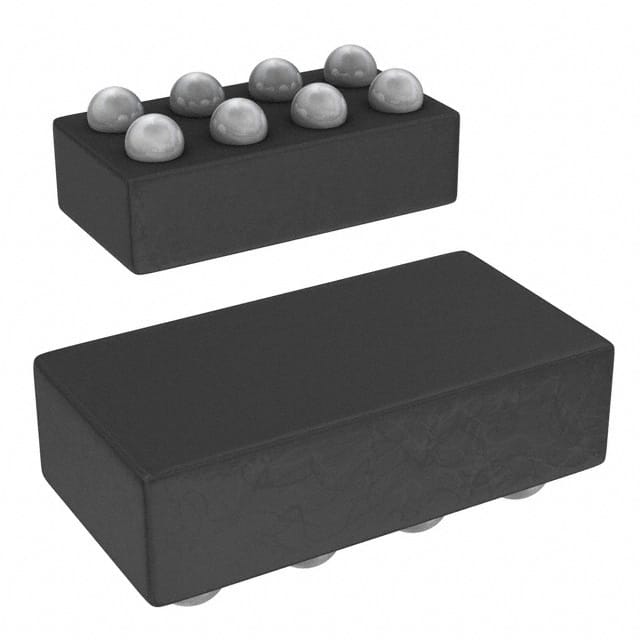
The MAX14515AEWA+T is housed in an 8-bump Wafer-Level Package (WLP) measuring 1mm × 2mm, optimized for space-constrained camera module PCBs.
| Pin/Terminal | Circuit Role | Design Meaning |
|---|---|---|
| VDD | Positive supply input | Accepts +2.7V to +5.5V; powers internal charge pump and logic |
| GND | Ground reference | Common return for supply, I²C, and high-voltage output stage |
| SCL | I²C clock input | Controls timing of register access; requires pull-up to VDD |
| SDA | I²C data I/O | Bidirectional line for configuration and DAC value loading |
| OUTP | Positive high-voltage output | Differential output terminal driving one side of liquid lens capacitor |
| OUTN | Negative high-voltage output | Differential output terminal driving opposite side of liquid lens capacitor |
| EN | Enable input | Active-high logic control for global device power-up/shutdown |
| NC | No connect | Unbonded bump; must be left floating or grounded per layout guidelines |
Key Features
| Feature | Design Value |
|---|---|
| Charge-pump + H-bridge integration | Eliminates need for external inductors or transformers, reducing BOM count and board area by >30% vs discrete solutions |
| Guaranteed monotonic DAC | Ensures predictable lens position response across full 8-bit range-critical for repeatable auto-focus calibration |
| Two-tier power management | Enables system-level power sequencing: shutdown for deep sleep, sleep for rapid wake-up with retained state |
| 1mm × 2mm WLP | Fits within 2.5mm × 2.5mm camera module keep-out zones, enabling sub-5mm total module height |
| ±15kV HBM ESD on outputs | Withstands direct ESD events during lens module handling without external TVS diodes |
Applications
| Smartphone Front-Facing Camera | Medical Endoscope Imaging |
|---|---|
Use Scenario: Compact front-camera module requiring fast, silent autofocus in thin bezel designs. IC Role / Device Role / Timing Role: High-voltage differential driver controlling liquid lens curvature via I²C-set DAC output. Use Value: 42VRMS output drives standard 220pF lens at 1kHz; 1mm × 2mm WLP enables placement directly adjacent to lens barrel. | Use Scenario: Miniaturized endoscopic probe needing reliable focus adjustment under sterilization constraints. IC Role / Device Role / Timing Role: Low-power lens actuator with shutdown mode preserving battery during intermittent use. Use Value: ≤500nA shutdown current extends disposable probe battery life; ±15kV HBM withstands repeated clinical handling. |
| Automotive Cabin Monitoring | AR Glasses Eye-Tracking |
Use Scenario: Driver-facing camera operating in wide temperature range inside vehicle cabin. IC Role / Device Role / Timing Role: Temperature-stable lens driver supporting focus adaptation during thermal cycling. Use Value: –40°C to +85°C operation ensures consistent 42VRMS output performance across automotive ambient conditions. | Use Scenario: Ultra-low-profile near-eye display requiring millisecond-scale focus shift between eye positions. IC Role / Device Role / Timing Role: I²C-configurable DAC delivering precise voltage steps to liquid lens for gaze-contingent rendering. Use Value: 8-bit monotonic DAC enables reproducible lens displacement steps; sleep mode allows <3µA background hold current. |
Equivalent & Alternatives
The following parts are listed as comparable options for similar liquid lens driver applications.
| Alternative Part | Technical Difference | Application Difference | Selection Advice |
|---|---|---|---|
| MAX14516AEWA+T | Same WLP package and I²C interface, but supports higher 50VRMS output (min) into 220pF at 1.0kHz | Required where lens actuation demands >42VRMS; otherwise pin-and-code compatible | Select MAX14516AEWA+T only if lens datasheet specifies ≥45VRMS drive requirement |
| TI LP8866QRHBRQ1 | LED driver with integrated boost and analog dimming; no DAC or liquid lens-specific control logic | Not a functional replacement; used only in hybrid LED+focus modules where shared boost is beneficial | Consider only when reusing existing TI-based LED power architecture and adding lens drive as secondary function |
Compared with MAX14515AEWA+T, MAX14516AEWA+T offers higher voltage headroom for demanding lenses, while LP8866QRHBRQ1 serves unrelated LED biasing roles-neither is drop-in, and MAX14515AEWA+T remains optimal for dedicated, space-constrained liquid lens control.
Availability
MAX14515AEWA+T is available at Aetrix Electronics and suitable for smartphone camera modules, medical endoscopes, automotive cabin monitoring systems, and AR glasses requiring stable component supply and long-term manufacturability.
Supply support for MAX14515AEWA+T includes scheduled delivery planning, volume procurement assistance, BOM continuity management, traceable sourcing, and lifecycle availability coordination for OEM customers, industrial embedded developers, connected-device designers, and electronics production programs.
Manufacturer
Maxim Integrated (now part of Analog Devices) designs precision analog and mixed-signal ICs for power, sensing, and interface applications in portable, industrial, and automotive systems.
The MAX14515AEWA+T belongs to Maxim's high-voltage analog driver product line, engineered specifically for miniaturized liquid lens actuation in space- and power-constrained imaging modules.
FAQ
What is the maximum output voltage capability of the MAX14515AEWA+T?
The MAX14515AEWA+T delivers up to 42VRMS minimum into a 220pF liquid lens load at 1.0kHz. This is measured under specified conditions per the official datasheet (Rev 0, 2008). The actual peak-to-peak voltage exceeds 120V, enabling reliable actuation of commercially available electrowetting lenses. Output amplitude is digitally set via its 8-bit I²C-controlled DAC.
Does the MAX14515AEWA+T require external inductors or transformers?
No, the MAX14515AEWA+T integrates a charge-pump-based boost converter and H-bridge, eliminating the need for external inductors or transformers. This allows full high-voltage generation using only small ceramic capacitors. The design reduces solution size and simplifies layout-critical for camera modules where board area is at a premium. All power conversion circuitry is contained within the IC.
How does the power management of the MAX14515AEWA+T support battery-powered devices?
The MAX14515AEWA+T supports two ultra-low-power states: shutdown mode draws ≤500nA and resets all registers, while sleep mode maintains POR functionality and consumes <3µA during I²C inactivity. Both modes enable aggressive power gating in smartphones and portable medical devices. The EN pin allows hardware-controlled entry/exit, and I²C activity automatically wakes the device from sleep.
Is the MAX14515AEWA+T compatible with standard I²C buses?
Yes, the MAX14515AEWA+T implements a standard I²C-compatible 2-wire interface with SCL and SDA pins operating at 1.8V–5.5V logic levels. It supports standard-mode (100kHz) and fast-mode (400kHz) speeds. No level shifting is required when interfacing with common baseband processors or microcontrollers. Register maps and ACK/NACK behavior conform to I²C specification Rev. 6.
What package type and dimensions does the MAX14515AEWA+T use?
The MAX14515AEWA+T uses an 8-bump Wafer-Level Package (WLP) measuring 1.0mm × 2.0mm with 0.4mm pitch. This ultra-compact package is qualified for reflow soldering and designed for direct placement adjacent to liquid lens elements in camera modules. The NC bump must remain unconnected, and thermal pads are not included-board-level thermal relief relies on copper pour under the package.
MAX14515AEWA+T Specifications
- Product attributes
- Attribute value
- Manufacturer:
- Analog Devices Inc./Maxim Integrated
- Series:
- -
- Package/Case:
- 8-WFBGA, WLBGA
- Packaging:
- Tape & Reel (TR)
- Product Status:
- Active
- Programmable:
- Not Verified
- Type:
- Liquid Lens Driver
- Applications:
- -
- Mounting Type:
- Surface Mount
- Supplier Device Package:
- 8-WLP
- Grade:
- -
- Qualification:
- -
MAX14515AEWA+T FAQ
1.How can I place an order for MAX14515AEWA+T through Aetrix?
Please submit a Request for Quotation (RFQ) for MAX14515AEWA+T on Aetrix. Our sales agent will provide a competitive quotation and guide you through the order confirmation once you accept the terms.
2.Are the price and stock information for MAX14515AEWA+T reliable?
The price and inventory of MAX14515AEWA+T are updated periodically and may fluctuate due to market conditions. Stock and pricing data are typically refreshed every 24 hours. Quotation validity for MAX14515AEWA+T is usually 5 days.
3.What payment methods are accepted for MAX14515AEWA+T?
We accept Wire Transfer, PayPal, Credit Card, Western Union, MoneyGram, and Escrow for MAX14515AEWA+T transactions.
Note: Certain payment methods may incur a processing fee.
4.How is shipping managed for MAX14515AEWA+T?
MAX14515AEWA+T orders can be shipped via leading logistics carriers, including DHL, UPS, FedEx, TNT, or Registered Mail.
Once your MAX14515AEWA+T order is processed, you will receive an email with the shipment details and tracking number.
Note: Tracking information may take up to 24 hours to appear. Express delivery typically takes 3–5 business days.
5.How can I obtain technical support or documentation for MAX14515AEWA+T?
For technical support, including MAX14515AEWA+T datasheets, pinout diagrams, or application guidance, please contact our engineering support team. They can provide detailed documentation and assistance for your MAX14515AEWA+T requirements.
6.How does Aetrix verify that MAX14515AEWA+T is sourced from the original manufacturer or authorized distributors?
All MAX14515AEWA+T products on Aetrix are procured from qualified distributors and authorized channels. Our dedicated quality assurance team conducts strict verification, including traceability checks and, if necessary, third-party testing. This ensures that MAX14515AEWA+T meets industry standards.
7.What is the process for return or replacement of MAX14515AEWA+T?
All MAX14515AEWA+T units undergo pre-shipment inspection (PSI). If there is an issue with MAX14515AEWA+T, returns or replacements are accepted under the following conditions:
1.Quantity discrepancies, incorrect items, or visible external defects (such as breakage or corrosion), acknowledged by Aetrix.
2.The issue is reported within 90 days of delivery.
3.The MAX14515AEWA+T part is unused and in its original packaging.
Return procedure for MAX14515AEWA+T:
1.Submit a request within 90 days.
2.Obtain a Return Material Authorization (RMA) from Aetrix.
MAX14515AEWA+T Tags

-
CAP200DG-TL
Power Integrations
-
ATSHA204A-MAHDA-T
Microchip Technology

-
ATSHA204A-SSHDA-T
Microchip Technology

-
ATSHA204A-STUCZ-T
Microchip Technology
-
ATECC608B-MAHDA-T
Microchip Technology
-
ATECC608B-MAHCZ-S
Microchip Technology

-
ATECC608B-SSHDA-T
Microchip Technology
-
ATECC608B-MAHDA-S
Microchip Technology
-
ATECC608A-MAHDA-S
Microchip Technology
-
ATECC608B-MAVDA-T
Microchip Technology

-
ATECC608A-SSHDA-T
Microchip Technology
-
ATECC508A-MAHDA-T
Microchip Technology
Tech Hub

A practical engineering guide to 3.3V and 5V logic compatibility, input thresholds, resistor dividers, translator ICs, MOSFET level shifting, I2C pull-ups, timing limits and power-sequencing risks.

The 74HC595 uses push-pull logic outputs, while the TPIC6B595 uses 50 V open-drain DMOS sinks for higher-power loads. This guide compares timing, current limits, 3.3 V interfacing, load wiring, thermal…

The 74HC595 converts serial data into eight stable parallel outputs. This guide covers pin functions, shift and storage timing, OE and MR behavior, drive-current limits, cascading, voltage compatibilit…

A technical comparison of level-sensitive latches and edge-triggered flip-flops, covering timing windows, setup and hold limits, master–slave operation, time borrowing, race-through, HDL inference and…

A D latch stores one bit while Enable controls when data can pass. This reference covers gate-level operation, truth tables, transparency, setup and hold timing, LE versus OE, common ICs and practical …

An SR latch stores one bit through cross-coupled feedback. This engineering reference covers NOR and NAND implementations, truth tables, forbidden-state recovery, gated operation, switch debouncing, fa…

Latch circuits retain one bit through feedback. This technical reference covers SR and D latches, truth tables, transparency, timing limits, latch-versus-flip-flop behavior, applications and common log…

An engineering guide to LED driver operation, constant-current and constant-voltage outputs, linear and switching topologies, dimming, IC selection, calculations, replacement compatibility, and fault c…

Operational amplifier guide covering op amp basics, feedback, ideal vs real op amps, common configurations, buffer circuits, offset, bias current, gain-bandwidth, slew rate, rail-to-rail limits and sel…

Jumper cables guide covering safe connection order, red and black clamp placement, final ground connection, cable gauge, length, clamp quality, copper vs CCA cables, jump starter comparison and battery…


