
 My Inquiry
 My Account


Analog Devices Inc./Maxim Integrated MAX14570EZT+T
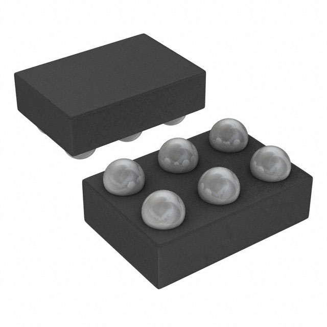
- Part No.:
- MAX14570EZT+T
- Manufacturer:
- Analog Devices Inc./Maxim Integrated
- Category:
- Motor Drivers, Controllers
- Package:
- 6-XFBGA, WLBGA
- Datasheet:
-
 MAX14570EZT+T.pdf
- Description:
- IC MOTOR DRIVER 2.3V-5.5V 6WLP
- Quantity:
- Payment:

- Shipping:

Inventory:2,827
Please send an inquiry. Send us your inquiry, and we will respond immediately.
Product details
Overview
The MAX14570EZT+T from Maxim Integrated is a high-efficiency, I²C-programmable voice coil motor (VCM) driver for autofocus camera modules. It delivers 0–100mA output current with 10-bit resolution (97.7µA/LSB), supports selectable PWM or linear output modes, and integrates slew-rate control and spread-spectrum oscillation to reduce EMI in space-constrained mobile imaging systems.
For engineers reviewing the MAX14570EZT+T datasheet, MAX14570EZT+T pinout, MAX14570EZT+T application, or MAX14570EZT+T equivalent, key selection criteria include VCM current accuracy (±2% FSR gain error), thermal shutdown at +150°C, 6µA shutdown current, 0.78mm × 1.35mm WLP package, and I²C-adjustable ringing compensation for actuator settling time optimization.
Technical Context
The MAX14570EZT+T implements an integrated H-bridge with programmable 10-bit DAC control via I²C, enabling precise DC current regulation across ISOURCE and ISINK terminals. Its dual-mode operation-PWM (1.2–5.8MHz selectable frequency) or linear-allows trade-offs between efficiency (~80% at 60mA, VDD = 2.8V) and noise performance.
EMI mitigation is achieved through two independent features: user-configurable slew-rate limiting (SR[2:0] + SRL bits) and spread-spectrum clocking (SS bit, ±20% bandwidth). Ringing compensation uses a digitally reconstructed lowpass filter (tunable cutoff via FSHP/FSHPD registers) to match VCM mechanical resonance and reduce shutter lag.
Key Specifications
| Parameter | Value and Actual Design Meaning |
|---|---|
| VCM Output Range | 0–100mA with 10-bit resolution (97.7µA/LSB); enables fine-grained focus positioning in compact camera modules. |
| Output Modes | PWM or linear mode selectable via I²C register 0x06; PWM offers higher efficiency, linear mode reduces switching noise. |
| Efficiency | ~80% at 60mA output with VDD = 2.8V; minimizes power dissipation and thermal load in battery-powered devices. |
| Shutdown Current | ≤6µA max; preserves battery life during idle periods in smartphone camera subsystems. |
| Package | 0.78mm × 1.35mm × 0.35mm, 6-bump WLP, 0.4mm pitch; supports ultra-thin module designs with minimal PCB footprint. |
| Operating Temp | -40°C to +85°C ambient; qualified for consumer mobile device environments including thermal cycling during use. |
| I²C Interface | Standard-mode (100kHz) and fast-mode (1000kHz) compatible; supports host microcontroller integration without additional level-shifting. |
Pinout & Package
The MAX14570EZT+T is housed in a 0.78mm × 1.35mm × 0.35mm, 6-bump wafer-level package (WLP) with 0.4mm pitch. Bump-side-down top view places all six terminals on a 2×3 grid.
| Pin/Terminal | Circuit Role | Design Meaning |
|---|---|---|
| A1 | SDA | I²C open-drain serial data line; requires external pull-up; enables bidirectional register read/write for configuration and diagnostics. |
| A2 | ISINK | Voice coil current sink terminal; connects to low side of VCM; internally protected against short-to-rail and open-load faults. |
| A3 | GND | Analog/digital ground reference; must be connected to low-impedance system ground plane to ensure current-sense accuracy and EMI control. |
| B1 | SCL | I²C open-drain serial clock input; requires external pull-up; used to enter/exit shutdown mode by holding low >769.5µs. |
| B2 | ISOURCE | Voice coil current source terminal; connects to high side of VCM; supports both PWM switching and linear sourcing based on register setting. |
| B3 | VDD | Main supply input (2.3V–5.5V); bypassed with 0.1µF capacitor to GND; powers internal regulator, DAC, and H-bridge stages. |
Key Features
| Feature | Design Value |
|---|---|
| Tunable ringing compensation | Digitally adjustable lowpass filter (via registers 0x02, 0x07) reduces mechanical overshoot and cuts VCM settling time-critical for sub-100ms autofocus convergence. |
| I²C-adjustable PWM frequency | Five discrete output frequencies (1.2–5.8MHz) selected via FREQ[2:0]; allows EMI peak avoidance and optimization for specific VCM inductance/resistance. |
| On-board diagnostics | Real-time OPEN/SHORT/PROT flag reporting (register 0x05) enables fail-safe detection of VCM disconnection, short circuits, or overcurrent-reducing field failure risk. |
| Programmable slew-rate limiting | SR[2:0] + SRL bits adjust edge rates (e.g., 3.6ns to 37ns rise time); balances EMI reduction against efficiency loss in PWM mode. |
| Flexible power-state control | Three operational modes (shutdown/standby/active) managed entirely via I²C timing; eliminates need for external enable logic or sequencers. |
Applications
| Smartphone Autofocus Modules | Tablet Camera Actuators |
|---|---|
Use Scenario: Compact rear-facing camera module requiring rapid, silent focus adjustment under variable lighting and battery constraints. IC Role / Device Role / Timing Role: VCM driver providing closed-loop current control to position lens elements; responds to host MCU commands within 250µs (tST-A). Use Value: 10-bit current resolution and tunable ringing compensation reduce shutter lag by up to 40% versus fixed-gain drivers, improving capture success rate. | Use Scenario: Dual-camera tablet system where EMI from one module must not interfere with Wi-Fi/Bluetooth coexistence. IC Role / Device Role / Timing Role: EMI-conscious VCM actuator driver using spread-spectrum clocking and slew-rate limiting to suppress conducted/radiated emissions. Use Value: Spread-spectrum mode (±20% frequency dither) lowers peak spectral energy by >10dB, easing RF compliance testing without shielding add-ons. |
| Ultrathin Wearable Cameras | Industrial Barcode Scanner Focus |
Use Scenario: Sub-5mm-thick AR glasses camera needing minimal board area and thermal footprint. IC Role / Device Role / Timing Role: Space-optimized VCM driver in 0.78mm × 1.35mm WLP; operates from single 3.3V rail with <60µA standby current. Use Value: 6-bump WLP package saves >65% PCB area vs. comparable QFN solutions, enabling optical stack miniaturization. | Use Scenario: Rugged handheld scanner requiring reliable autofocus across temperature extremes and mechanical shock. IC Role / Device Role / Timing Role: Fault-tolerant VCM driver with integrated diagnostics (OPEN/SHORT detection) and thermal shutdown at +150°C. Use Value: On-chip diagnostics report VCM integrity before each focus cycle, preventing misfocus events caused by connector wear or coil fatigue. |
Equivalent & Alternatives
The following parts are listed as comparable options for similar VCM driver applications.
| Alternative Part | Technical Difference | Application Difference | Selection Advice |
|---|---|---|---|
| DRV2605LRTVT | Integrated haptic driver with VCM support; lacks dedicated ringing compensation; 8-bit current resolution (156µA/LSB) vs. 10-bit. | Targeted at haptics-first systems where VCM is secondary; no spread-spectrum EMI reduction. | Choose DRV2605LRTVT only if shared haptic/VCM actuation is required and 10-bit precision is unnecessary. |
| TI DRV2667YZFT | Higher voltage range (2.7–5.5V); includes analog input option; no I²C-adjustable slew rate; fixed 2.5MHz PWM frequency. | Better suited for industrial scanners with analog control interfaces; less flexible for mobile EMI tuning. | Select DRV2667YZFT when analog control or guaranteed 2.5MHz operation outweighs programmable EMI features. |
Compared with DRV2605LRTVT and DRV2667YZFT, the MAX14570EZT+T provides superior autofocus precision (10-bit vs. 8-bit), configurable EMI suppression (spread-spectrum + slew-rate), and dedicated ringing compensation-making it optimal for high-performance mobile imaging where settling time and spectral cleanliness are critical.
Availability
The MAX14570EZT+T is available at Aetrix Electronics and suitable for smartphone camera modules, tablet imaging subsystems, and ultrathin wearable optics requiring stable component supply, long-term lifecycle support, and traceable sourcing.
Supply support for MAX14570EZT+T includes scheduled delivery planning, volume procurement assistance, BOM continuity management, traceable sourcing, and lifecycle availability coordination for OEM customers, industrial embedded developers, connected-device designers, and electronics production programs.
Manufacturer
Maxim Integrated, now part of Analog Devices, designs precision analog, mixed-signal, and power management ICs for demanding industrial, automotive, and consumer applications.
The MAX14570EZT+T belongs to Maxim's camera interface and autofocus driver product line, engineered specifically for low-power, high-accuracy VCM control in space- and noise-constrained mobile imaging systems.
FAQ
What is the maximum output current capability of the MAX14570EZT+T?
The MAX14570EZT+T delivers a programmable output current range of 0 to 100mA with 10-bit resolution (97.7µA/LSB). This full-scale capability is specified across the operating temperature range (-40°C to +85°C) and supply voltage range (2.3V to 5.5V), supporting high-force VCM actuators used in premium smartphone cameras. The device maintains ±2% full-scale range (FSR) gain error and ±0.75% FSR offset error under these conditions.
Does the MAX14570EZT+T support both PWM and linear output modes?
Yes, the MAX14570EZT+T supports both PWM and linear output modes, selected via the PWM_LIN bit (bit 1) in register 0x06. In PWM mode, ISOURCE switches at programmable frequencies (1.2–5.8MHz) to regulate average current; in linear mode, it provides continuous current sourcing. Mode selection is fully software-controlled over I²C, enabling dynamic adaptation to noise or efficiency requirements without hardware changes.
How does the MAX14570EZT+T reduce electromagnetic interference (EMI)?
The MAX14570EZT+T reduces EMI through two independent, I²C-configurable features: spread-spectrum clocking (SS bit in register 0x06), which dithers the PWM frequency by ±20% to lower peak spectral energy, and slew-rate limiting (SRL + SR[2:0] bits in register 0x08), which controls edge rates to reduce high-frequency harmonics. Both features are validated in the datasheet's FFT plots (Figures 13–14) and ripple current measurements.
What diagnostic capabilities does the MAX14570EZT+T provide for VCM health monitoring?
The MAX14570EZT+T provides real-time VCM diagnostics via its Status register (0x05). When DIAG = 1, it reports OPEN (open-circuit), SHORT (short-to-rail or ISOURCE–ISINK short), and PROT (overcurrent) conditions. Diagnostics use a 6mA test current and complete within 1ms. These flags enable predictive maintenance and fault recovery in camera modules without requiring external sense circuitry.
What package type and dimensions does the MAX14570EZT+T use?
The MAX14570EZT+T uses a 0.78mm × 1.35mm × 0.35mm, 6-bump wafer-level package (WLP) with 0.4mm pitch. This ultra-compact package is designed for direct chip-on-flex or chip-on-board integration in thin camera modules. The bump map is defined as A1=SDA, A2=ISINK, A3=GND, B1=SCL, B2=ISOURCE, B3=VDD-matching the mechanical layout shown in the datasheet's Figure 8.
MAX14570EZT+T Specifications
- Product attributes
- Attribute value
- Manufacturer:
- Analog Devices Inc./Maxim Integrated
- Series:
- -
- Package/Case:
- 6-XFBGA, WLBGA
- Packaging:
- Tape & Reel (TR)
- Product Status:
- Obsolete
- Motor Type - Stepper:
- -
- Motor Type - AC, DC:
- Voice Coil Motor
- Function:
- Driver - Fully Integrated, Control and Power Stage
- Output Configuration:
- Half Bridge
- Interface:
- I2C
- Technology:
- Bi-CMOS
- Step Resolution:
- -
- Applications:
- Camera
- Current - Output:
- 100mA
- Voltage - Supply:
- 2.3V ~ 5.5V
- Voltage - Load:
- 2.3V ~ 5.5V
- Operating Temperature:
- -40°C ~ 150°C (TJ)
- Grade:
- -
- Qualification:
- -
- Mounting Type:
- Surface Mount
- Supplier Device Package:
- 6-WLP (0.78x1.35)
MAX14570EZT+T FAQ
1.How can I place an order for MAX14570EZT+T through Aetrix?
Please submit a Request for Quotation (RFQ) for MAX14570EZT+T on Aetrix. Our sales agent will provide a competitive quotation and guide you through the order confirmation once you accept the terms.
2.Are the price and stock information for MAX14570EZT+T reliable?
The price and inventory of MAX14570EZT+T are updated periodically and may fluctuate due to market conditions. Stock and pricing data are typically refreshed every 24 hours. Quotation validity for MAX14570EZT+T is usually 5 days.
3.What payment methods are accepted for MAX14570EZT+T?
We accept Wire Transfer, PayPal, Credit Card, Western Union, MoneyGram, and Escrow for MAX14570EZT+T transactions.
Note: Certain payment methods may incur a processing fee.
4.How is shipping managed for MAX14570EZT+T?
MAX14570EZT+T orders can be shipped via leading logistics carriers, including DHL, UPS, FedEx, TNT, or Registered Mail.
Once your MAX14570EZT+T order is processed, you will receive an email with the shipment details and tracking number.
Note: Tracking information may take up to 24 hours to appear. Express delivery typically takes 3–5 business days.
5.How can I obtain technical support or documentation for MAX14570EZT+T?
For technical support, including MAX14570EZT+T datasheets, pinout diagrams, or application guidance, please contact our engineering support team. They can provide detailed documentation and assistance for your MAX14570EZT+T requirements.
6.How does Aetrix verify that MAX14570EZT+T is sourced from the original manufacturer or authorized distributors?
All MAX14570EZT+T products on Aetrix are procured from qualified distributors and authorized channels. Our dedicated quality assurance team conducts strict verification, including traceability checks and, if necessary, third-party testing. This ensures that MAX14570EZT+T meets industry standards.
7.What is the process for return or replacement of MAX14570EZT+T?
All MAX14570EZT+T units undergo pre-shipment inspection (PSI). If there is an issue with MAX14570EZT+T, returns or replacements are accepted under the following conditions:
1.Quantity discrepancies, incorrect items, or visible external defects (such as breakage or corrosion), acknowledged by Aetrix.
2.The issue is reported within 90 days of delivery.
3.The MAX14570EZT+T part is unused and in its original packaging.
Return procedure for MAX14570EZT+T:
1.Submit a request within 90 days.
2.Obtain a Return Material Authorization (RMA) from Aetrix.
MAX14570EZT+T Tags

-
DRV2603RUNR
Texas Instruments

-
DRV8837CDSGR
Texas Instruments

-
DRV8837DSGR
Texas Instruments
-
DRV8838DSGR
Texas Instruments

-
DRV8839DSSR
Texas Instruments

-
EMC2301-1-ACZL-TR
Microchip Technology
-
DRV8231ADSGR
Texas Instruments

-
EMC2302-2-AIZL-TR
Microchip Technology

-
DRV8800PWPR
Texas Instruments
-
DRV8835DSSR
Texas Instruments

-
EMC2303-1-KP-TR
Microchip Technology

-
DRV8876PWPR
Texas Instruments
Tech Hub

A practical engineering guide to 3.3V and 5V logic compatibility, input thresholds, resistor dividers, translator ICs, MOSFET level shifting, I2C pull-ups, timing limits and power-sequencing risks.

The 74HC595 uses push-pull logic outputs, while the TPIC6B595 uses 50 V open-drain DMOS sinks for higher-power loads. This guide compares timing, current limits, 3.3 V interfacing, load wiring, thermal…

The 74HC595 converts serial data into eight stable parallel outputs. This guide covers pin functions, shift and storage timing, OE and MR behavior, drive-current limits, cascading, voltage compatibilit…

A technical comparison of level-sensitive latches and edge-triggered flip-flops, covering timing windows, setup and hold limits, master–slave operation, time borrowing, race-through, HDL inference and…

A D latch stores one bit while Enable controls when data can pass. This reference covers gate-level operation, truth tables, transparency, setup and hold timing, LE versus OE, common ICs and practical …

An SR latch stores one bit through cross-coupled feedback. This engineering reference covers NOR and NAND implementations, truth tables, forbidden-state recovery, gated operation, switch debouncing, fa…

Latch circuits retain one bit through feedback. This technical reference covers SR and D latches, truth tables, transparency, timing limits, latch-versus-flip-flop behavior, applications and common log…

An engineering guide to LED driver operation, constant-current and constant-voltage outputs, linear and switching topologies, dimming, IC selection, calculations, replacement compatibility, and fault c…

Operational amplifier guide covering op amp basics, feedback, ideal vs real op amps, common configurations, buffer circuits, offset, bias current, gain-bandwidth, slew rate, rail-to-rail limits and sel…

Jumper cables guide covering safe connection order, red and black clamp placement, final ground connection, cable gauge, length, clamp quality, copper vs CCA cables, jump starter comparison and battery…


