
 My Inquiry
 My Account


Analog Devices Inc./Maxim Integrated MAX1457CCJ
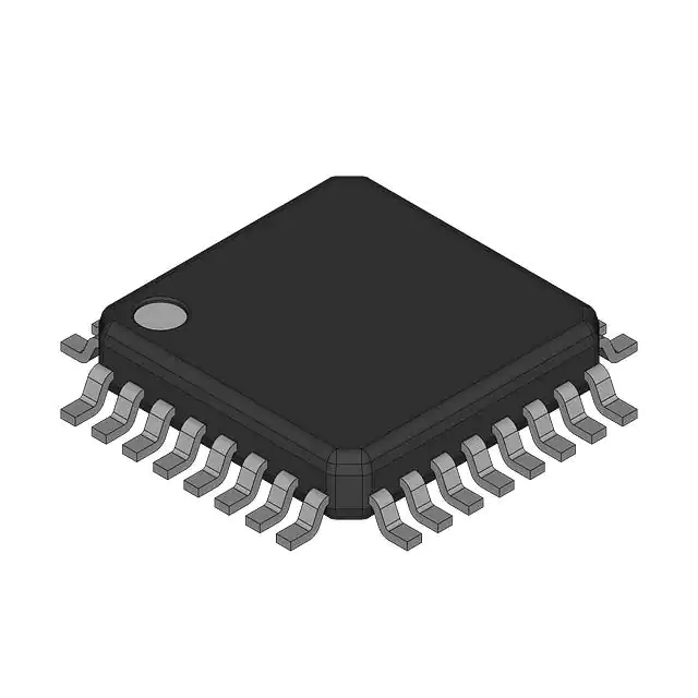
- Part No.:
- MAX1457CCJ
- Manufacturer:
- Analog Devices Inc./Maxim Integrated
- Category:
- Analog to Digital Converters (ADC)
- Package:
- 32-VQFN Exposed Pad
- Datasheet:
-
 MAX1457CCJ.pdf
- Description:
- SIGNAL CONDITIONER FOR SENSOR
- Quantity:
- Payment:

- Shipping:

Inventory:2,155
Please send an inquiry. Send us your inquiry, and we will respond immediately.
Product details
Overview
MAX1457CCJ from Maxim Integrated is a 32-pin TQFP analog sensor signal processor optimized for piezoresistive sensor calibration and compensation. It integrates a 3-bit programmable-gain amplifier (54–306 V/V), 12-bit ADC, five 16-bit DACs, programmable current source (0.1–2.0 mA), and uncommitted op amp. It achieves ±0.1% total error relative to sensor repeatability in pressure transducer modules operating from 0°C to +70°C.
For engineers reviewing the MAX1457CCJ datasheet, MAX1457CCJ pinout, MAX1457CCJ application, or MAX1457CCJ equivalent, this device supports multislope temperature compensation across up to 120 segments, ratiometric 5V output, and SPI/MicroWire EEPROM interfacing for production-grade sensor calibration systems.
Technical Context
The MAX1457CCJ implements closed-loop analog signal conditioning using a switched-capacitor PGA with input-referred offset trimming (±100 mV) and 16-bit DAC-controlled gain/offset/temperature coefficients. Its 12-bit ADC digitizes bridge voltage (BDRIVE) to select one of up to 120 EEPROM-stored correction pairs for OFFSET TC and FSO TC DACs.
Compensation occurs via dual-path analog injection: DC offset correction through OFSTDAC summing at PGA output, and full-span adjustment via FSODAC-modulated bridge current. Second-order nonlinearity is corrected by resistive feedback from LINOUT to ISRC using the 16-bit FSO LIN DAC.
Key Specifications
| Parameter | Value and Actual Design Meaning |
|---|---|
| Operating Temp Range | 0°C to +70°C - Specifies industrial-grade qualification; no derating required below +70°C. |
| PGA Gain Range | 54 V/V to 306 V/V - Eight discrete gain steps enabling precise scaling of 5–30 mV/V sensor outputs. |
| Bridge Current Range | 0.1 mA to 2.0 mA - Programmable excitation with 15 nA resolution for matched sensor drive and thermal stability. |
| DAC Resolution | 16-bit - Enables ±0.2 mV (±0.005% FSO) calibration step size for offset, FSO, and temperature coefficients. |
| ADC Resolution | 12-bit - Provides sufficient granularity to address 120 temperature segments over full operating range. |
| Serial Interface | SPI/MicroWire-compatible - Direct connection to external 93C66 EEPROM without level-shifting or protocol translation. |
| Output Settling Time | <1 ms - Ensures rapid stabilization after coefficient updates during automated test sequences. |
Pinout & Package
MAX1457CCJ is housed in a 32-lead TQFP package (7 mm × 7 mm, 0.5 mm pitch) with exposed thermal pad. Pin functions are validated per Maxim's 19-1342 Rev 1 datasheet (1998) and match the TQFP pin configuration diagram on page 11.
| Pin/Terminal | Circuit Role | Design Meaning |
|---|---|---|
| INP / INM | Sensor differential input | Rail-to-rail inputs (>1 MΩ impedance) accept 5–30 mV/V bridge signals directly. |
| VOUT | PGA output | High-impedance buffered output; requires 0.1 µF capacitor to VSS for stability. |
| ISRC | Current-source reference | Connects to 50 kΩ resistor to VSS to set bridge current range and linearity. |
| FSODAC / OTCDAC / FSOTCDAC / OFSTDAC / LINDAC | DAC voltage outputs | Each drives dedicated compensation path; all require 0.1 µF bypass to VSS for noise immunity. |
| ECS / ECLK / EDI / EDO | EEPROM interface | CMOS-level SPI/MicroWire bus; ECS enables EEPROM write, EDO returns temp-comp data. |
| MCS | Master chip select | Active-high enable; internally pulled up - left open for normal operation. |
Key Features
| Feature | Design Value |
|---|---|
| Multislope temperature compensation | Supports up to 120 independent temperature segments using BDRIVE-measured bridge voltage as index. |
| Ratiometric output architecture | VOUT scales with VDD (5.0 V nominal), enabling direct interface with ratiometric ADCs without supply-voltage drift error. |
| Integrated 4–20 mA transmitter support | AMPOUT and ISRC pins allow implementation of 2-wire current loop with <5 external components. |
| Automated calibration workflow | Pretest/Calibration/Final Test sequence eliminates socket removal, reducing test cycle time and handling damage. |
| External EEPROM dependency | Relies on low-cost 93C66 (4096-bit) for coefficient storage - decouples calibration data from silicon, enabling field reprogramming. |
Applications
| Pressure Transducer Calibration | Industrial Process Monitoring |
|---|---|
Use Scenario: Automated bench calibration of silicon piezoresistive pressure sensors across -20°C to +85°C using thermally controlled ovens and digital voltmeters. IC Role / Device Role / Timing Role: Signal conditioner performing real-time offset, FSO, and temperature coefficient injection via DACs synchronized to EEPROM read cycles. Use Value: Reduces calibration error from ±5% FSO to ±0.1% FSO without manual potentiometer adjustment or firmware changes. | Use Scenario: Embedded pressure sensing in HVAC control panels requiring stable 4–20 mA output over 15-year service life. IC Role / Device Role / Timing Role: Analog front-end providing temperature-compensated ratiometric output converted to current loop via external transistor and RA=50 Ω sense resistor. Use Value: Eliminates need for high-stability voltage references; REF02 bandgap suffices due to MAX1457CCJ's internal gain/offset correction. |
| Automotive Fuel Rail Sensing | Medical Disposable Pressure Sensors |
Use Scenario: High-volume fuel rail pressure monitoring where sensor modules must meet AEC-Q200 stress requirements and pass end-of-line functional test. IC Role / Device Role / Timing Role: Calibration engine executing pretest → EEPROM coefficient load → final verification in single socket, minimizing handler wear. Use Value: Enables parallel testing of up to five modules via shared EDI/ECLK/EDO bus and individual MCS/ECS control lines. | Use Scenario: Single-use blood pressure transducers requiring factory-calibrated accuracy better than ±0.5% FSO across patient temperature range. IC Role / Device Role / Timing Role: Final-stage signal conditioner compensating for batch-specific piezoresistor drift and packaging-induced stress nonlinearity. Use Value: Achieves ±0.1% FSO accuracy using only passive external components (resistors, capacitors) and no laser trimming. |
Equivalent & Alternatives
The following parts are listed as comparable options for similar piezoresistive sensor signal conditioning applications.
| Alternative Part | Technical Difference | Application Difference | Selection Advice |
|---|---|---|---|
| MAX1457CWI | Same die, 28-pin wide SO package; lower thermal dissipation (1 W vs. 889 mW); no N.C. pins at positions 4,16,22,32. | Preferred for space-constrained PCBs where TQFP reflow compatibility is not required. | Select MAX1457CWI when board area is critical and thermal load is low; MAX1457CCJ preferred for higher power density or automated optical inspection. |
| ASIC1024 (Honeywell) | Proprietary ASIC with fixed compensation algorithm; no external EEPROM interface; 10-bit internal DACs. | Limited to Honeywell-specified sensors; no multislope or user-defined curve fitting. | Choose ASIC1024 only for drop-in replacement in legacy Honeywell designs; MAX1457CCJ offers field-upgradable calibration and broader sensor compatibility. |
Compared with MAX1457CWI, the MAX1457CCJ provides superior thermal management in high-density layouts and supports more robust automated test connectivity via its full 32-pin TQFP layout; versus ASIC1024, it delivers programmable multislope compensation and vendor-agnostic EEPROM-based calibration essential for multi-sensor manufacturing lines.
Availability
MAX1457CCJ is available at Aetrix Electronics and suitable for pressure transducer calibration, industrial process monitoring, automotive fuel rail sensing, and medical disposable pressure sensors requiring stable component supply across extended production lifecycles.
Supply support for MAX1457CCJ includes scheduled delivery planning, volume procurement assistance, BOM continuity management, traceable sourcing, and lifecycle availability coordination for OEM customers, industrial embedded developers, connected-device designers, and electronics production programs.
Manufacturer
Maxim Integrated (now part of Analog Devices) is a U.S.-based semiconductor company specializing in precision analog, mixed-signal, and high-reliability ICs for industrial, automotive, and medical applications.
The MAX1457 product line was designed specifically for automated, high-volume calibration of piezoresistive sensors - integrating pretest data acquisition, coefficient computation, and final verification into a single IC to reduce test cost and improve yield.
FAQ
What is the maximum number of temperature segments supported by the MAX1457CCJ for multislope compensation?
The MAX1457CCJ supports up to 120 temperature segments for multislope compensation. This is achieved by using its 12-bit ADC to measure the bridge voltage (BDRIVE) and selecting corresponding OFFSET TC and FSO TC coefficients stored in external EEPROM. Each segment provides ±0.2 mV (±0.005% FSO) resolution, enabling sub-0.1% FSO residual error after full calibration. The MAX1457CCJ's segmentation capability is fixed in silicon and does not depend on EEPROM size beyond the minimum 4096-bit requirement.
Does the MAX1457CCJ require an external EEPROM, and if so, which part is recommended?
Yes, the MAX1457CCJ requires an external EEPROM to store calibration coefficients - specifically the 93C66 (4096-bit, Microwire-compatible) as confirmed in the datasheet Figure 5 and Applications Information section. The MAX1457CCJ interfaces directly via ECS/ECLK/EDI/EDO pins with no level-shifting needed. While other 93-series EEPROMs may function, the 93C66 is the only device validated for timing, fan-out, and voltage compatibility with the MAX1457CCJ's serial interface.
Can the MAX1457CCJ be used with sensors other than piezoresistive types?
Yes, the MAX1457CCJ can condition other resistive sensors including accelerometers and strain gauges, provided external components are added to adapt their output format. The datasheet explicitly states this capability in the General Description section and notes that "a few external components" - such as bridge completion resistors or gain-setting networks - are required. However, full temperature compensation features (e.g., multislope FSO TC) were optimized for piezoresistive behavior and may require empirical validation for non-piezoresistive elements.
What is the purpose of the NBIAS pin on the MAX1457CCJ, and how must it be configured?
The NBIAS pin on the MAX1457CCJ sets the internal bias current for the oscillator and analog circuitry. It must be connected to VDD through a 400 kΩ resistor (RBIAS) and bypassed to VSS with a 0.1 µF capacitor, as specified in the Pin Description table and Figure 5. This configuration establishes the 100 kHz internal clock frequency and ensures stable operation of the PGA and DACs. Omitting RBIAS or using incorrect resistance values causes gain inaccuracy and timing errors in EEPROM communication.
How does the MAX1457CCJ achieve rail-to-rail analog output despite using a 5V supply?
The MAX1457CCJ achieves rail-to-rail output through its internal PGA architecture and output buffer design, allowing VOUT to swing from (VSS + 0.25 V) to (VDD – 0.25 V) under 5 kΩ load conditions. This 0.25 V headroom is maintained across temperature and process variation, enabling true ratiometric operation where output scale tracks VDD precisely. The specification is verified in the Electrical Characteristics table (page 2) and applies directly to the MAX1457CCJ's 32-pin TQFP variant.
MAX1457CCJ Specifications
- Product attributes
- Attribute value
- Manufacturer:
- Analog Devices Inc./Maxim Integrated
- Series:
- -
- Package/Case:
- 32-VQFN Exposed Pad
- Packaging:
- Bulk
- Product Status:
- Active
- Number of Bits:
- 12
- Sampling Rate (Per Second):
- -
- Number of Inputs:
- 1
- Input Type:
- Pseudo-Differential
- Data Interface:
- MICROWIRE, Serial, SPI
- Configuration:
- MUX-S/H-ADC
- Ratio - S/H:ADC:
- 1:1
- Number of A/D Converters:
- 1
- Architecture:
- SAR
- Reference Type:
- External
- Voltage - Supply, Analog:
- 2.7V ~ 5.25V
- Voltage - Supply, Digital:
- 2.7V ~ 5.25V
- Features:
- -
- Operating Temperature:
- 0°C ~ 70°C
- Supplier Device Package:
- 32-QFP-N (7x7)
- Mounting Type:
- Surface Mount
- Grade:
- -
- Qualification:
- -
MAX1457CCJ FAQ
1.How can I place an order for MAX1457CCJ through Aetrix?
Please submit a Request for Quotation (RFQ) for MAX1457CCJ on Aetrix. Our sales agent will provide a competitive quotation and guide you through the order confirmation once you accept the terms.
2.Are the price and stock information for MAX1457CCJ reliable?
The price and inventory of MAX1457CCJ are updated periodically and may fluctuate due to market conditions. Stock and pricing data are typically refreshed every 24 hours. Quotation validity for MAX1457CCJ is usually 5 days.
3.What payment methods are accepted for MAX1457CCJ?
We accept Wire Transfer, PayPal, Credit Card, Western Union, MoneyGram, and Escrow for MAX1457CCJ transactions.
Note: Certain payment methods may incur a processing fee.
4.How is shipping managed for MAX1457CCJ?
MAX1457CCJ orders can be shipped via leading logistics carriers, including DHL, UPS, FedEx, TNT, or Registered Mail.
Once your MAX1457CCJ order is processed, you will receive an email with the shipment details and tracking number.
Note: Tracking information may take up to 24 hours to appear. Express delivery typically takes 3–5 business days.
5.How can I obtain technical support or documentation for MAX1457CCJ?
For technical support, including MAX1457CCJ datasheets, pinout diagrams, or application guidance, please contact our engineering support team. They can provide detailed documentation and assistance for your MAX1457CCJ requirements.
6.How does Aetrix verify that MAX1457CCJ is sourced from the original manufacturer or authorized distributors?
All MAX1457CCJ products on Aetrix are procured from qualified distributors and authorized channels. Our dedicated quality assurance team conducts strict verification, including traceability checks and, if necessary, third-party testing. This ensures that MAX1457CCJ meets industry standards.
7.What is the process for return or replacement of MAX1457CCJ?
All MAX1457CCJ units undergo pre-shipment inspection (PSI). If there is an issue with MAX1457CCJ, returns or replacements are accepted under the following conditions:
1.Quantity discrepancies, incorrect items, or visible external defects (such as breakage or corrosion), acknowledged by Aetrix.
2.The issue is reported within 90 days of delivery.
3.The MAX1457CCJ part is unused and in its original packaging.
Return procedure for MAX1457CCJ:
1.Submit a request within 90 days.
2.Obtain a Return Material Authorization (RMA) from Aetrix.
MAX1457CCJ Tags
-
ADC081C021CIMKX/NOPB
Texas Instruments

-
MCP3021A5T-E/OT
Microchip Technology
-
TLA2024IRUGR
Texas Instruments
-
MCP3221A5T-E/OT
Microchip Technology
-
MCP3221A5T-I/OT
Microchip Technology
-
MCP3221A4T-E/OT
Microchip Technology
-
MCP3221A6T-E/OT
Microchip Technology
-
MCP3221A0T-E/OT
Microchip Technology
-
MCP3221A1T-E/OT
Microchip Technology

-
ADC121S021CIMFX/NOPB
Texas Instruments

-
MCP3001-I/MS
Microchip Technology

-
MCP3001-I/SN
Microchip Technology
Tech Hub

A practical engineering guide to 3.3V and 5V logic compatibility, input thresholds, resistor dividers, translator ICs, MOSFET level shifting, I2C pull-ups, timing limits and power-sequencing risks.

The 74HC595 uses push-pull logic outputs, while the TPIC6B595 uses 50 V open-drain DMOS sinks for higher-power loads. This guide compares timing, current limits, 3.3 V interfacing, load wiring, thermal…

The 74HC595 converts serial data into eight stable parallel outputs. This guide covers pin functions, shift and storage timing, OE and MR behavior, drive-current limits, cascading, voltage compatibilit…

A technical comparison of level-sensitive latches and edge-triggered flip-flops, covering timing windows, setup and hold limits, master–slave operation, time borrowing, race-through, HDL inference and…

A D latch stores one bit while Enable controls when data can pass. This reference covers gate-level operation, truth tables, transparency, setup and hold timing, LE versus OE, common ICs and practical …

An SR latch stores one bit through cross-coupled feedback. This engineering reference covers NOR and NAND implementations, truth tables, forbidden-state recovery, gated operation, switch debouncing, fa…

Latch circuits retain one bit through feedback. This technical reference covers SR and D latches, truth tables, transparency, timing limits, latch-versus-flip-flop behavior, applications and common log…

An engineering guide to LED driver operation, constant-current and constant-voltage outputs, linear and switching topologies, dimming, IC selection, calculations, replacement compatibility, and fault c…

Operational amplifier guide covering op amp basics, feedback, ideal vs real op amps, common configurations, buffer circuits, offset, bias current, gain-bandwidth, slew rate, rail-to-rail limits and sel…

Jumper cables guide covering safe connection order, red and black clamp placement, final ground connection, cable gauge, length, clamp quality, copper vs CCA cables, jump starter comparison and battery…


