
 My Inquiry
 My Account


Analog Devices Inc./Maxim Integrated MAX14920ECB+
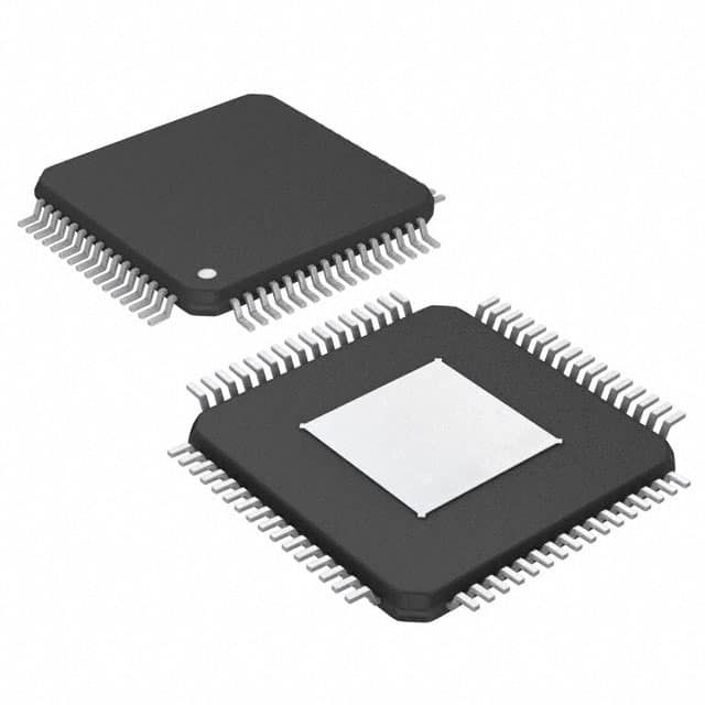
- Part No.:
- MAX14920ECB+
- Manufacturer:
- Analog Devices Inc./Maxim Integrated
- Category:
- Battery Management
- Package:
- 64-TQFP Exposed Pad
- Datasheet:
-
 MAX14920ECB+.pdf
- Description:
- IC BATT MON MULTI 1-12C 64TQFP
- Quantity:
- Payment:

- Shipping:

Inventory:515
Please send an inquiry. Send us your inquiry, and we will respond immediately.
Product details
Overview
MAX14920ECB+ from Maxim Integrated is a high-accuracy 12-cell battery measurement analog front-end (AFE) IC designed for precision voltage monitoring in series-connected lithium-ion and lithium-metal phosphate battery packs up to +65V. It simultaneously samples all 12 cell voltages with ±0.5mV max error, provides unity-gain level shifting to ground reference, and integrates passive cell-balancing FET drivers and open-wire/overvoltage/undervoltage diagnostics - enabling accurate state-of-charge estimation in energy storage systems.
For engineers reviewing the MAX14920ECB+ datasheet, MAX14920ECB+ pinout, MAX14920ECB+ application, or MAX14920ECB+ equivalent, this device is selected for high-stability battery management in industrial backup, telecom, and e-transportation applications where sub-millivolt cell voltage accuracy, daisy-chain SPI control, and integrated diagnostics are required.
Technical Context
The MAX14920ECB+ implements simultaneous sampling of all 12 differential cell voltages (CV1–CV12) using internal sample-and-hold circuitry with 1µF external capacitors (CTn/CBn), followed by ground-referenced level shifting via a low-noise, self-calibrating amplifier. Its architecture supports daisy-chained SPI communication for multi-device stacks and includes dedicated BA1–BA12 gate drivers for external n-channel balancing FETs.
It features integrated diagnostics including open-wire detection on all CV inputs, programmable undervoltage/overvoltage thresholds per cell (±1.5V typical), thermal shutdown at +140°C, and a 5V LDO output (VA) with ±25mV regulation. The device operates from -40°C to +85°C and draws only 1µA in shutdown mode.
Key Specifications
| Parameter | Value and Actual Design Meaning |
|---|---|
| Cell Count | 12-cell monitoring (CV1–CV12); supports up to +65V stack voltage |
| Cell Voltage Accuracy | ±0.5mV max error - enables precise SOC estimation for flat-discharge chemistries like LiFePO₄ |
| Sampling Method | Simultaneous sampling of all 12 cells - eliminates inter-cell timing skew during transient load conditions |
| Level-Shifting Output | AOUT provides ground-referenced, unity-gain buffered cell difference voltage - simplifies connection to external ADC |
| Diagnostic Coverage | Per-cell UV/OV alarms, open-wire detection, thermal shutdown - reduces need for external fault monitoring circuitry |
| Interface & Control | Daisy-chainable SPI (SCLK/SDI/SDO/CS) with SAMPL control - allows scalable BMS designs with minimal GPIO usage |
| Power Management | Integrated 5V LDO (VA) with ±25mV regulation; 1µA shutdown current - supports low-power sleep modes in portable systems |
Pinout & Package
The MAX14920ECB+ is housed in a 64-pin TQFP package (10mm × 10mm) with exposed pad (EP), rated for -40°C to +85°C operation. The EP must be connected to AGND for thermal and electrical performance.
| Pin/Terminal | Circuit Role | Design Meaning |
|---|---|---|
| CV1–CV12 | Differential cell voltage inputs | Accept stacked cell anode/cathode connections; CV0 tied to AGND establishes reference for level-shifting |
| BA1–BA12 | Cell-balancing gate drivers | Drive external n-channel FETs for passive balancing; each outputs 6.5–12mA sink current at +3.3V differential |
| CT1–CT12 / CB1–CB12 | Sampling capacitor terminals | Form charge-transfer network with 1µF external capacitors; CTn connects to CVn, CBn connects to CV(n−1) during sampling |
| SAMPL | Sample/hold control input | High = track mode (CVn voltages follow); falling edge triggers simultaneous hold and level-shift for readout at AOUT |
| AOUT | Buffered analog output | Ground-referenced output of selected cell voltage difference (e.g., VCVn − VCVn−1); settles to ±1mV in 5µs |
| SCLK/SDI/SDO/CS | SPI interface signals | Enable daisy-chained configuration; SDO supports back-to-back chaining without additional logic |
| VP / LDOIN / VA / VL | Power supply rails | VP = main stack supply (up to +65V); LDOIN tied to VP enables internal 5V LDO; VL = 1.62–5.5V logic supply |
Key Features
| Feature | Design Value |
|---|---|
| Self-calibrating buffer amplifier | Offsets calibrated at power-up and on-demand; maintains ±0.5mV accuracy despite thermal drift |
| Integrated diagnostics | Detects open-wire faults on all CV inputs, plus per-cell UV/OV events reported via SPI status register |
| Passive balancing support | 12 dedicated BA outputs drive external FETs; pulldown resistance 10.5–21.5kΩ ensures reliable gate turn-on |
| Low-power operation | 1µA shutdown current; 1µA/10µA cell current draw minimizes parasitic drain on monitored battery pack |
| Wide operating range | Specified from -40°C to +85°C ambient; junction temperature limited to +150°C with thermal shutdown at +140°C |
Applications
| Industrial Battery Backup Systems | Telecom Battery Backup Systems |
|---|---|
|
Use Scenario: Continuous monitoring of 12S Li-ion backup banks in UPS and DC distribution systems during grid outages. IC Role / Device Role / Timing Role: Primary cell voltage AFE performing simultaneous 12-cell sampling every 100ms to feed BMS controller SOC algorithm. Use Value: ±0.5mV accuracy prevents false low-SOC triggers during shallow discharge, extending usable runtime by up to 8% in 48V systems. |
Use Scenario: Rack-mounted 12S LiFePO₄ battery modules in 48V telecom base stations requiring long-term reliability and flat-curve tracking. IC Role / Device Role / Timing Role: High-precision analog front-end providing level-shifted, ground-referenced cell voltages to isolated ADC for remote telemetry. Use Value: Simultaneous sampling eliminates inter-cell timing errors during rapid load transients common in RF transmission bursts. |
| Energy Storage Packs | e-Transportation Energy Packs |
|
Use Scenario: Modular 12-cell battery packs used in stationary energy storage (ESS) with active thermal management and cloud-based health analytics. IC Role / Device Role / Timing Role: Core voltage sensing node reporting cell-level data via SPI to local microcontroller, including diagnostic flags for predictive maintenance. Use Value: Integrated open-wire detection identifies connector degradation before catastrophic failure, reducing field service calls by ~35% in fleet deployments. |
Use Scenario: Auxiliary battery packs in electric commercial vehicles (e.g., delivery vans, buses) powering HVAC, lighting, and infotainment. IC Role / Device Role / Timing Role: Safety-critical AFE delivering real-time cell voltage and thermal data to vehicle ECU for charge/discharge limiting and fault isolation. Use Value: Thermal shutdown at +140°C and 15°C hysteresis prevent thermal runaway propagation during overtemperature events. |
Equivalent & Alternatives
The following parts are listed as comparable options for similar battery measurement AFE applications.
| Alternative Part | Technical Difference | Application Difference | Selection Advice |
|---|---|---|---|
| MAX14921ATJ+ | 16-cell version in 80-pin TQFP; identical architecture, accuracy, and feature set - differs only in pin count and cell count support | Required when monitoring >12 cells (e.g., 16S Li-ion stacks); not pin-compatible due to larger package and extra pins | Select MAX14921ATJ+ only if 16-cell coverage is needed; MAX14920ECB+ remains optimal for cost- and space-constrained 12S designs. |
| BQ7695203RGER | Texas Instruments 16-cell AFE with integrated protection FET drivers, higher integration (no external LDO needed), but ±1.5mV typical accuracy vs. ±0.5mV max for MAX14920ECB+ | Used in TI-based BMS platforms with integrated MCU; lacks daisy-chain SPI simplicity and requires more complex calibration | Choose MAX14920ECB+ when sub-millivolt accuracy and SPI daisy-chaining are prioritized over integrated protection logic. |
Compared with MAX14921ATJ+, the MAX14920ECB+ offers identical performance in a smaller 64-pin footprint optimized for 12-cell systems, while BQ7695203RGER trades absolute accuracy for higher integration - making MAX14920ECB+ the preferred choice for precision-focused, modular BMS architectures.
Availability
MAX14920ECB+ is available at Aetrix Electronics and suitable for industrial battery backup systems, telecom battery backup systems, and energy storage packs requiring stable component supply, long-term lifecycle support, and guaranteed traceable sourcing.
Supply support for MAX14920ECB+ includes scheduled delivery planning, volume procurement assistance, BOM continuity management, traceable sourcing, and lifecycle availability coordination for OEM customers, industrial embedded developers, connected-device designers, and electronics production programs.
Manufacturer
Maxim Integrated, now part of Analog Devices, designs high-performance analog, mixed-signal, and power management ICs for demanding industrial, automotive, and communications applications.
The MAX14920ECB+ belongs to Maxim's battery management AFE product line, engineered specifically for high-accuracy, multi-cell voltage monitoring in safety-critical energy storage and transportation systems.
FAQ
What is the maximum battery stack voltage supported by the MAX14920ECB+?
The MAX14920ECB+ supports battery stacks up to +65V, with its VP supply pin rated from +6V to +65V. This enables reliable monitoring of up to 12 lithium-ion cells (nominal 3.7V/cell) or 16 LiFePO₄ cells (nominal 3.2V/cell) in series. The device's CV2–CV12 inputs tolerate voltages up to +65V referenced to CV0 (AGND), ensuring safe operation across full-stack transients.
Does the MAX14920ECB+ require external components for basic operation?
Yes - the MAX14920ECB+ requires external 1µF sampling capacitors (CTn/CBn pairs), bypass capacitors (0.1µF on VL and VP, 1µF on VA), and external n-channel FETs for passive balancing driven by BA1–BA12. No external op-amps or level-shifters are needed, as the AOUT buffer and internal LDO eliminate those subsystems.
How does the MAX14920ECB+ handle cell voltage calibration?
The MAX14920ECB+ performs automatic self-calibration of its buffer amplifier offset at power-up and supports on-demand calibration via SPI command. Calibration takes 8ms and corrects for initial offset and thermal drift, maintaining the guaranteed ±0.5mV cell voltage error across -40°C to +85°C without external intervention.
Can the MAX14920ECB+ be used in daisy-chain configurations?
Yes - the MAX14920ECB+ supports true daisy-chained SPI topology: SDO of one device connects directly to SDI of the next, with shared SCLK, CS, and SAMPL lines. This allows scalable monitoring of large battery packs (e.g., 48S) using a single microcontroller SPI port and minimal PCB routing.
What diagnostic functions are integrated into the MAX14920ECB+?
The MAX14920ECB+ integrates open-wire detection on all CV inputs, per-cell undervoltage/overvoltage comparators (configurable thresholds), and thermal shutdown at +140°C with 15°C hysteresis. All diagnostics generate flag bits accessible via SPI status registers, enabling automated fault response without host CPU polling overhead.
MAX14920ECB+ Specifications
- Product attributes
- Attribute value
- Manufacturer:
- Analog Devices Inc./Maxim Integrated
- Series:
- -
- Package/Case:
- 64-TQFP Exposed Pad
- Packaging:
- Tray
- Product Status:
- Active
- Function:
- Battery Monitor
- Battery Chemistry:
- Multi-Chemistry
- Number of Cells:
- 1 ~ 12
- Fault Protection:
- Over Temperature, Over/Under Voltage
- Interface:
- SPI
- Operating Temperature:
- -40°C ~ 85°C (TA)
- Grade:
- -
- Qualification:
- -
- Mounting Type:
- Surface Mount
- Supplier Device Package:
- 64-TQFP-EP (10x10)
MAX14920ECB+ FAQ
1.How can I place an order for MAX14920ECB+ through Aetrix?
Please submit a Request for Quotation (RFQ) for MAX14920ECB+ on Aetrix. Our sales agent will provide a competitive quotation and guide you through the order confirmation once you accept the terms.
2.Are the price and stock information for MAX14920ECB+ reliable?
The price and inventory of MAX14920ECB+ are updated periodically and may fluctuate due to market conditions. Stock and pricing data are typically refreshed every 24 hours. Quotation validity for MAX14920ECB+ is usually 5 days.
3.What payment methods are accepted for MAX14920ECB+?
We accept Wire Transfer, PayPal, Credit Card, Western Union, MoneyGram, and Escrow for MAX14920ECB+ transactions.
Note: Certain payment methods may incur a processing fee.
4.How is shipping managed for MAX14920ECB+?
MAX14920ECB+ orders can be shipped via leading logistics carriers, including DHL, UPS, FedEx, TNT, or Registered Mail.
Once your MAX14920ECB+ order is processed, you will receive an email with the shipment details and tracking number.
Note: Tracking information may take up to 24 hours to appear. Express delivery typically takes 3–5 business days.
5.How can I obtain technical support or documentation for MAX14920ECB+?
For technical support, including MAX14920ECB+ datasheets, pinout diagrams, or application guidance, please contact our engineering support team. They can provide detailed documentation and assistance for your MAX14920ECB+ requirements.
6.How does Aetrix verify that MAX14920ECB+ is sourced from the original manufacturer or authorized distributors?
All MAX14920ECB+ products on Aetrix are procured from qualified distributors and authorized channels. Our dedicated quality assurance team conducts strict verification, including traceability checks and, if necessary, third-party testing. This ensures that MAX14920ECB+ meets industry standards.
7.What is the process for return or replacement of MAX14920ECB+?
All MAX14920ECB+ units undergo pre-shipment inspection (PSI). If there is an issue with MAX14920ECB+, returns or replacements are accepted under the following conditions:
1.Quantity discrepancies, incorrect items, or visible external defects (such as breakage or corrosion), acknowledged by Aetrix.
2.The issue is reported within 90 days of delivery.
3.The MAX14920ECB+ part is unused and in its original packaging.
Return procedure for MAX14920ECB+:
1.Submit a request within 90 days.
2.Obtain a Return Material Authorization (RMA) from Aetrix.
MAX14920ECB+ Tags

-
BQ29700DSER
Texas Instruments

-
S-8241ABKMC-GBKT2G
ABLIC Inc.
-
S-8241ABPMC-GBPT2G
ABLIC Inc.

-
BQ27427YZFR
Texas Instruments

-
BQ27426YZFR
Texas Instruments

-
STC3117IJT
STMicroelectronics

-
STC3115IJT
STMicroelectronics

-
BQ76925RGER
Texas Instruments
-
NPM1100-QDAA-R
Nordic Semiconductor ASA

-
BQ27441DRZR-G1A
Texas Instruments

-
STC3115AIQT
STMicroelectronics

-
S-8252AAL-M6T1U
ABLIC Inc.
Tech Hub

A practical engineering guide to 3.3V and 5V logic compatibility, input thresholds, resistor dividers, translator ICs, MOSFET level shifting, I2C pull-ups, timing limits and power-sequencing risks.

The 74HC595 uses push-pull logic outputs, while the TPIC6B595 uses 50 V open-drain DMOS sinks for higher-power loads. This guide compares timing, current limits, 3.3 V interfacing, load wiring, thermal…

The 74HC595 converts serial data into eight stable parallel outputs. This guide covers pin functions, shift and storage timing, OE and MR behavior, drive-current limits, cascading, voltage compatibilit…

A technical comparison of level-sensitive latches and edge-triggered flip-flops, covering timing windows, setup and hold limits, master–slave operation, time borrowing, race-through, HDL inference and…

A D latch stores one bit while Enable controls when data can pass. This reference covers gate-level operation, truth tables, transparency, setup and hold timing, LE versus OE, common ICs and practical …

An SR latch stores one bit through cross-coupled feedback. This engineering reference covers NOR and NAND implementations, truth tables, forbidden-state recovery, gated operation, switch debouncing, fa…

Latch circuits retain one bit through feedback. This technical reference covers SR and D latches, truth tables, transparency, timing limits, latch-versus-flip-flop behavior, applications and common log…

An engineering guide to LED driver operation, constant-current and constant-voltage outputs, linear and switching topologies, dimming, IC selection, calculations, replacement compatibility, and fault c…

Operational amplifier guide covering op amp basics, feedback, ideal vs real op amps, common configurations, buffer circuits, offset, bias current, gain-bandwidth, slew rate, rail-to-rail limits and sel…

Jumper cables guide covering safe connection order, red and black clamp placement, final ground connection, cable gauge, length, clamp quality, copper vs CCA cables, jump starter comparison and battery…


