
 My Inquiry
 My Account


Analog Devices Inc./Maxim Integrated MAX14948EWE+
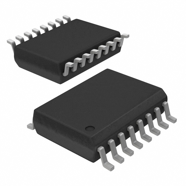
- Part No.:
- MAX14948EWE+
- Manufacturer:
- Analog Devices Inc./Maxim Integrated
- Category:
- Digital Isolators
- Package:
- 16-SOIC (0.295", 7.50mm Width)
- Datasheet:
-
 MAX14948EWE+.pdf
- Description:
- DGTL ISO 5KV RS422/RS485 16SOIC
- Quantity:
- Payment:

- Shipping:

Inventory:1,772
Please send an inquiry. Send us your inquiry, and we will respond immediately.
Product details
Overview
The MAX14948EWE+ from Maxim Integrated is a 5kVRMS galvanically isolated, half-duplex RS-485/RS-422 transceiver with integrated LDO, ±30kV HBM ESD protection on cable-side pins (A/B), and true fail-safe receiver logic. It operates from 1.71V–5.5V logic supply (VDDA) and 4.5V–5.5V isolated supply (VDDB), supports up to 500kbps data rate, and enables robust industrial bus communication in ground-noise-prone environments such as PLC backplanes.
For engineers reviewing the MAX14948EWE+ datasheet, MAX14948EWE+ pinout, MAX14948EWE+ application, or MAX14948EWE+ equivalent, key selection criteria include isolation voltage rating (5000VRMS/60s), bus loading capability (1/8-unit load, 256-node support), integrated LDO output (5V, 300mA), thermal shutdown threshold (+160°C), and CMTI performance (35kV/μs).
Technical Context
This device implements capacitive galvanic isolation between UART-side (GNDA/VDDA) and cable-side (GNDB/VDDB) domains, enabling signal integrity across large ground-potential differences. Its half-duplex architecture uses shared A/B differential bus lines controlled by DE (driver enable) and RE (receiver enable), with SBA indicating side-B power status.
The integrated 5V LDO (VLDO input, VDDB output) eliminates need for external isolated DC/DC for cable-side power, while undervoltage lockout (VUVLOA = 1.58V typ, VUVLOB = 2.7V typ) prevents erroneous operation during brownout. Receiver features fixed -125mV typical differential threshold with 15mV hysteresis and true fail-safe behavior-guaranteeing RXD high when A/B are open, shorted, or terminated.
Key Specifications
| Parameter | Value and Actual Design Meaning |
|---|---|
| Isolation Voltage | 5000VRMS for 60s - meets basic insulation requirements per UL1577 and IEC 60747-5-5; enables safety-critical industrial interfaces. |
| Data Rate | 500kbps maximum - supports medium-speed industrial protocols (e.g., Modbus RTU at full duplex-equivalent timing). |
| Bus Loading | 1/8-unit load receiver - allows up to 256 transceivers on one RS-485 bus without violating 32-unit-load standard limit. |
| ESD Protection | ±30kV HBM on A/B pins to GNDB - eliminates need for external TVS diodes in most industrial ESD environments. |
| LDO Output | 5V ±5%, 300mA current limit - powers isolated side directly from VLDO ≥4.68V; simplifies system-level isolated power design. |
| CMTI | 35kV/μs - ensures reliable data transmission under fast common-mode transients (e.g., motor switching noise). |
| Operating Temp | -40°C to +85°C - qualified for extended industrial temperature range without derating. |
Pinout & Package
MAX14948EWE+ is housed in a wide-body 16-pin SOIC (W16M+9 package) with 8mm creepage/clearance, RoHS-compliant, and rated for 150°C max junction temperature.
| Pin/Terminal | Circuit Role | Design Meaning |
|---|---|---|
| 1 VDDA | Logic-side power input | Bypass with 0.1µF + 1µF to GNDA; supplies internal logic and interface circuitry (TXD/RE/DE/SBA/RXD). |
| 2,8 GNDA | Logic-side ground reference | Reference for all digital signals; must be isolated from GNDB by ≥8mm clearance/creepage. |
| 3 RXD | Receiver data output | Active-low when (VA–VB) < –200mV; high-Z when RE = high; pulled high during UVLO or fail-safe conditions. |
| 4 RE | Receiver enable (active-low) | Internal 4.5µA pulldown to GNDA; drives RXD high-Z when high; enables receiver when low. |
| 5 DE | Driver enable (active-high) | Internal 4.5µA pulldown to GNDA; enables A/B outputs when high; disables to high-Z when low. |
| 6 TXD | Driver input | Internal 4.5µA pullup to VDDA; controls A/B polarity: TXD high → A high/B low; TXD low → A low/B high. |
| 7 SBA | Side-B active indicator | Open-drain output pulled up internally to VDDA via 5kΩ; asserts low only when VDDB ≥ VUVLOB and side-B powered. |
| 9,15 GNDB | Cable-side ground reference | Reference for A/B differential pair, VDDB, VLDO; galvanically isolated from GNDA; critical for isolation barrier integrity. |
| 10,14 N.C. | No connection | Not internally bonded; must remain unconnected on PCB to preserve isolation integrity and creepage distance. |
| 11 VLDO | LDO input voltage | Accepts 4.68V–14V relative to GNDB; enables internal 5V LDO; leave unconnected or tie to GNDB to disable LDO. |
| 12 A | Noninverting bus line | Differential driver output / receiver input; ±30kV HBM ESD protected to GNDB; connects to RS-485 bus A line. |
| 13 B | Inverting bus line | Differential driver output / receiver input; ±30kV HBM ESD protected to GNDB; connects to RS-485 bus B line. |
| 16 VDDB | Cable-side power input/output | Output of internal LDO when VLDO powered; input for external 5V supply when VLDO disabled; bypass with 0.1µF + 1µF to GNDB. |
Key Features
| Feature | Design Value |
|---|---|
| Integrated 5V LDO | Eliminates need for external isolated DC/DC converter; reduces BOM count and layout complexity for cable-side power. |
| True fail-safe receiver | Guarantees RXD = high when A/B are open, shorted, or terminated - prevents spurious framing errors in idle bus states. |
| ±30kV HBM ESD on A/B | Meets IEC 61000-4-2 Level 4 immunity without external protection components, lowering system-level ESD design risk. |
| Thermal shutdown | Automatically forces driver outputs to high-Z at +160°C junction temp, preventing latch-up or permanent damage during fault conditions. |
| 1/8-unit load receiver | Enables 256-node RS-485 networks using standard 120Ω termination - ideal for dense industrial I/O modules and distributed control systems. |
Applications
| Industrial PLC Backplane Communication | Smart Power Meter Data Interface |
|---|---|
|
Use Scenario: Bidirectional Modbus RTU communication between CPU module and remote I/O racks in noisy factory environments with ground potential differences >10V. IC Role / Device Role / Timing Role: Isolated half-duplex RS-485 transceiver bridging UART domain (CPU) and field bus (I/O rack); handles DE/RE timing coordination and fail-safe bus idle detection. Use Value: 5000VRMS isolation breaks ground loops, while 35kV/μs CMTI rejects motor-drive-induced transients - ensuring error-free polling at 19.2kbps over 1km cable runs. |
Use Scenario: Secure, noise-immune data exchange between metrology IC and concentrator unit in ANSI C12.19-compliant smart meters deployed in substations. IC Role / Device Role / Timing Role: Isolated RS-485 interface providing galvanic separation between meter's high-voltage sensing section and low-voltage communication subsystem. Use Value: ±30kV HBM ESD protection withstands handling during field installation; 1/8-unit load supports daisy-chained multi-meter clusters without repeaters. |
| HVAC Building Management System | Factory Automation Sensor Network |
|
Use Scenario: Central controller communicating with distributed VAV boxes, chillers, and thermostats over long RS-485 trunk lines in commercial buildings with mixed grounding schemes. IC Role / Device Role / Timing Role: Half-duplex isolated transceiver managing shared bus arbitration via DE/RE control; SBA pin confirms cable-side power health before initiating transactions. Use Value: Integrated LDO powers bus side from single 12V rail, reducing external component count; true fail-safe prevents false triggers during HVAC actuator switching events. |
Use Scenario: Connecting vibration, temperature, and pressure sensors to edge gateway in automotive assembly line, where welding EMI exceeds 100V/ns common-mode slew rates. IC Role / Device Role / Timing Role: Robust isolated RS-485 node enabling deterministic sensor data collection at 500kbps; thermal shutdown protects against enclosure overheating during continuous operation. Use Value: 35kV/μs CMTI maintains bit integrity despite arc-welder transients; 256-node capacity supports future expansion of sensor density without bus redesign. |
Equivalent & Alternatives
The following parts are listed as comparable options for similar isolated RS-485 transceiver applications.
| Alternative Part | Technical Difference | Application Difference | Selection Advice |
|---|---|---|---|
| ADM2483BRWZ-REEL7 | 2.5kVRMS isolation (vs. 5kVRMS); no integrated LDO; requires external isolated 5V supply for bus side. | Lower isolation rating limits use in Class I hazardous locations; lacks LDO simplification for single-rail systems. | Select when cost sensitivity outweighs isolation margin and external isolated supply is already available. |
| ISO1500DWR | 5000VRMS isolation; 1Mbps max data rate; no integrated LDO; 1/4-unit load (128-node support vs. 256). | Higher speed suits faster protocols (e.g., PROFIBUS DP), but reduced bus loading requires repeaters for large networks. | Select when 1Mbps operation is required and bus node count ≤128; verify compatibility with existing 5V isolated supply rails. |
Compared with ADM2483BRWZ-REEL7 and ISO1500DWR, the MAX14948EWE+ uniquely combines 5kVRMS isolation, integrated 5V LDO, 1/8-unit load, and ±30kV HBM ESD - delivering lowest system-level BOM count and highest node density for industrial RS-485 networks operating up to 500kbps.
Availability
MAX14948EWE+ is available at Aetrix Electronics and suitable for industrial automation equipment, programmable logic controllers, HVAC control systems, and smart power metering applications requiring stable component supply across extended temperature ranges and long product lifecycles.
Supply support for MAX14948EWE+ includes scheduled delivery planning, volume procurement assistance, BOM continuity management, traceable sourcing, and lifecycle availability coordination for OEM customers, industrial embedded developers, connected-device designers, and electronics production programs.
Manufacturer
Maxim Integrated (now part of Analog Devices) designs precision analog, mixed-signal, and power management ICs for industrial, automotive, and communications markets, emphasizing reliability, integration, and ruggedized performance.
The MAX14948EWE+ belongs to Maxim's isolated interface product line, engineered specifically for noise-immune industrial communications where galvanic isolation, high ESD tolerance, and simplified power architecture are critical design requirements.
FAQ
What is the isolation voltage rating of the MAX14948EWE+ and how is it certified?
The MAX14948EWE+ is rated for 5000VRMS isolation for 60 seconds per UL1577 and IEC 60747-5-5 standards. It carries UL and cUL certification (File E351759) for basic insulation, with VIORM = 1200VPEAK and VIOWM = 848VRMS. This rating is verified through 100% production testing at 120% VISO (6000VRMS) for 1 second, ensuring consistent barrier integrity across all units.
Does the MAX14948EWE+ require an external isolated power supply for the cable side?
No - the MAX14948EWE+ integrates a 5V LDO with 300mA current limit, powered by VLDO (4.68V–14V input referenced to GNDB). When VLDO is supplied, VDDB becomes the regulated 5V output for the cable-side transceiver. If external 5V is available, VLDO can be tied to GNDB and VDDB used directly as input - eliminating need for external isolated DC/DC converters in most designs.
How does the true fail-safe feature of the MAX14948EWE+ improve system reliability?
The MAX14948EWE+ guarantees RXD = high when A/B inputs are open, shorted, or connected to a terminated bus with all drivers disabled. This is achieved via fixed receiver thresholds (-50mV to -200mV) and internal biasing. In practice, this prevents UART framing errors and false interrupts during bus initialization, cable disconnects, or multi-drop contention - significantly improving uptime in industrial networks.
What is the maximum number of MAX14948EWE+ devices supported on a single RS-485 bus?
The MAX14948EWE+ features a 1/8-unit load receiver input impedance, allowing up to 256 nodes on a single RS-485 bus while staying within the RS-485 standard's 32-unit load limit. This is confirmed by RIN = 96kΩ (min) and applies regardless of whether other transceivers on the same bus are standard (1-unit) or fractional-load devices.
Can the MAX14948EWE+ operate at data rates higher than 500kbps?
No - the MAX14948EWE+ is specified for a maximum data rate of 500kbps, validated across temperature (-40°C to +85°C) and supply conditions. Attempting higher rates may result in increased bit error rate due to propagation delay skew (tDSKEW = 144ns max) and limited driver rise/fall times (900ns max). For >500kbps, consider non-isolated or higher-speed isolated alternatives like ISO1500.
MAX14948EWE+ Specifications
- Product attributes
- Attribute value
- Manufacturer:
- Analog Devices Inc./Maxim Integrated
- Series:
- -
- Package/Case:
- 16-SOIC (0.295", 7.50mm Width)
- Packaging:
- Tube
- Product Status:
- Active
- Technology:
- Capacitive Coupling
- Type:
- RS422, RS485
- Isolated Power:
- No
- Number of Channels:
- 3
- Inputs - Side 1/Side 2:
- 2/1
- Channel Type:
- Unidirectional
- Voltage - Isolation:
- 5000Vrms
- Common Mode Transient Immunity (Min):
- 35kV/µs (Typ)
- Data Rate:
- 500kbps
- Propagation Delay tpLH / tpHL (Max):
- 1.04µs, 1.04µs
- Pulse Width Distortion (Max):
- -
- Rise / Fall Time (Typ):
- 900ns, 900ns (Max)
- Voltage - Supply:
- 1.71V ~ 5.5V, 4.5V ~ 5.5V
- Grade:
- -
- Qualification:
- -
- Operating Temperature:
- -40°C ~ 85°C
- Mounting Type:
- Surface Mount
- Supplier Device Package:
- 16-SOIC
MAX14948EWE+ FAQ
1.How can I place an order for MAX14948EWE+ through Aetrix?
Please submit a Request for Quotation (RFQ) for MAX14948EWE+ on Aetrix. Our sales agent will provide a competitive quotation and guide you through the order confirmation once you accept the terms.
2.Are the price and stock information for MAX14948EWE+ reliable?
The price and inventory of MAX14948EWE+ are updated periodically and may fluctuate due to market conditions. Stock and pricing data are typically refreshed every 24 hours. Quotation validity for MAX14948EWE+ is usually 5 days.
3.What payment methods are accepted for MAX14948EWE+?
We accept Wire Transfer, PayPal, Credit Card, Western Union, MoneyGram, and Escrow for MAX14948EWE+ transactions.
Note: Certain payment methods may incur a processing fee.
4.How is shipping managed for MAX14948EWE+?
MAX14948EWE+ orders can be shipped via leading logistics carriers, including DHL, UPS, FedEx, TNT, or Registered Mail.
Once your MAX14948EWE+ order is processed, you will receive an email with the shipment details and tracking number.
Note: Tracking information may take up to 24 hours to appear. Express delivery typically takes 3–5 business days.
5.How can I obtain technical support or documentation for MAX14948EWE+?
For technical support, including MAX14948EWE+ datasheets, pinout diagrams, or application guidance, please contact our engineering support team. They can provide detailed documentation and assistance for your MAX14948EWE+ requirements.
6.How does Aetrix verify that MAX14948EWE+ is sourced from the original manufacturer or authorized distributors?
All MAX14948EWE+ products on Aetrix are procured from qualified distributors and authorized channels. Our dedicated quality assurance team conducts strict verification, including traceability checks and, if necessary, third-party testing. This ensures that MAX14948EWE+ meets industry standards.
7.What is the process for return or replacement of MAX14948EWE+?
All MAX14948EWE+ units undergo pre-shipment inspection (PSI). If there is an issue with MAX14948EWE+, returns or replacements are accepted under the following conditions:
1.Quantity discrepancies, incorrect items, or visible external defects (such as breakage or corrosion), acknowledged by Aetrix.
2.The issue is reported within 90 days of delivery.
3.The MAX14948EWE+ part is unused and in its original packaging.
Return procedure for MAX14948EWE+:
1.Submit a request within 90 days.
2.Obtain a Return Material Authorization (RMA) from Aetrix.
MAX14948EWE+ Tags

-
ISO1212DBQR
Texas Instruments
-
ISO6721BDR
Texas Instruments
-
SI8710AC-B-ISR
Skyworks Solutions Inc.
-
ISO7720FDR
Texas Instruments
-
ISO7721DR
Texas Instruments
-
ISO7721FDR
Texas Instruments
-
SI8710CC-B-ISR
Skyworks Solutions Inc.
-
ISO6741FQDWRQ1
Texas Instruments

-
ISO7721DWVR
Texas Instruments
-
ISO7762FDBQR
Texas Instruments

-
ISO7741DWR
Texas Instruments
-
ISO7741FDWR
Texas Instruments
Tech Hub

A practical engineering guide to 3.3V and 5V logic compatibility, input thresholds, resistor dividers, translator ICs, MOSFET level shifting, I2C pull-ups, timing limits and power-sequencing risks.

The 74HC595 uses push-pull logic outputs, while the TPIC6B595 uses 50 V open-drain DMOS sinks for higher-power loads. This guide compares timing, current limits, 3.3 V interfacing, load wiring, thermal…

The 74HC595 converts serial data into eight stable parallel outputs. This guide covers pin functions, shift and storage timing, OE and MR behavior, drive-current limits, cascading, voltage compatibilit…

A technical comparison of level-sensitive latches and edge-triggered flip-flops, covering timing windows, setup and hold limits, master–slave operation, time borrowing, race-through, HDL inference and…

A D latch stores one bit while Enable controls when data can pass. This reference covers gate-level operation, truth tables, transparency, setup and hold timing, LE versus OE, common ICs and practical …

An SR latch stores one bit through cross-coupled feedback. This engineering reference covers NOR and NAND implementations, truth tables, forbidden-state recovery, gated operation, switch debouncing, fa…

Latch circuits retain one bit through feedback. This technical reference covers SR and D latches, truth tables, transparency, timing limits, latch-versus-flip-flop behavior, applications and common log…

An engineering guide to LED driver operation, constant-current and constant-voltage outputs, linear and switching topologies, dimming, IC selection, calculations, replacement compatibility, and fault c…

Operational amplifier guide covering op amp basics, feedback, ideal vs real op amps, common configurations, buffer circuits, offset, bias current, gain-bandwidth, slew rate, rail-to-rail limits and sel…

Jumper cables guide covering safe connection order, red and black clamp placement, final ground connection, cable gauge, length, clamp quality, copper vs CCA cables, jump starter comparison and battery…


