
 My Inquiry
 My Account


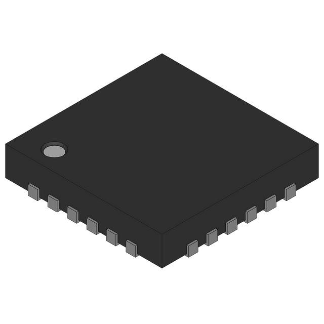
Analog Devices Inc./Maxim Integrated MAX14975ETG+
- Part No.:
- MAX14975ETG+
- Manufacturer:
- Analog Devices Inc./Maxim Integrated
- Category:
- Specialized
- Package:
- 24-WFQFN Exposed Pad
- Datasheet:
-
 MAX14975ETG+.pdf
- Description:
- DUAL USB 3.0 EQUALIZER/REDRIVER
- Quantity:
- Payment:

- Shipping:

Inventory:2,103
Please send an inquiry. Send us your inquiry, and we will respond immediately.
Product details
Overview
MAX14975ETG+ from Maxim Integrated is a dual-channel USB 3.0 (5 Gbps) equalizer/redriver IC designed to compensate for channel loss in industrial and embedded systems. It delivers programmable input equalization (up to 10 dB), output deemphasis (up to 4 dB), deterministic jitter ≤12 psP-P, random jitter ≤1 psRMS, and operates across -40°C to +85°C in a 24-pin TQFN package.
For engineers reviewing the MAX14975ETG+ datasheet, MAX14975ETG+ pinout, MAX14975ETG+ application, or MAX14975ETG+ equivalent, this page provides verified electrical parameters, USB 3.0 LFPS support details, power-state current values (standby <1 mW, active 304 mW), thermal resistance (θJA = 36°C/W), and real-world use cases in carrier boards and rack-server industrial PCs.
Technical Context
The MAX14975ETG+ implements two independent redriver channels with separate EQ_/DE_/OS_/ENRXD control logic per channel, enabling precise compensation of asymmetric trace/cable losses on both host and device sides of a SuperSpeed USB link. Each channel supports three-level input equalization and six-level output deemphasis, with explicit LFPS detection (100–300 mVP-P threshold) and squelch behavior.
Its advanced power management includes four defined states: standby (<1 mW), receiver detect (23 mW), dynamic power-down (82.5 mW), and active (304 mW), all triggered via ENRXD and CM pins. The device maintains USB 3.0 compliance mode (CM = 1) with full LFPS pass-through and no receiver detection or power-down activation.
Key Specifications
| Parameter | Value and Actual Design Meaning |
|---|---|
| Supply Voltage | 3.0 V to 3.6 V - ensures compatibility with standard 3.3 V industrial power rails and tolerates ±10% variation without regulation. |
| Data Rate Support | 5.0 Gbps - fully compliant with USB 3.0 SuperSpeed signaling, not USB 3.1/3.2 or Gen2+. |
| Deterministic Jitter | ≤12 psP-P - guarantees eye opening sufficient for USB 3.0 receiver margin at end-of-link after 30-inch FR4 traces. |
| Input Equalization | Up to 10 dB - compensates for high-frequency loss in long PCB traces or passive cables before signal degradation exceeds receiver tolerance. |
| Output Deemphasis | Up to 4 dB - reduces inter-symbol interference by attenuating high-frequency components in transition bits relative to nontransition bits. |
| ESD Protection | ±8 kV HBM on all pins - enables robust operation in industrial environments with frequent handling or unshielded connectors. |
| Thermal Resistance | θJA = 36°C/W - allows continuous operation at full load up to +85°C ambient when mounted on a 4-layer board with exposed pad soldered to ground plane. |
Pinout & Package
The MAX14975ETG+ is housed in a 4.0 mm × 4.0 mm, 24-pin TQFN-EP package with exposed pad (EP) internally connected to GND. The flow-through pin arrangement minimizes signal crosstalk and simplifies routing of differential pairs (RX1±/TX1±/RX2±/TX2±) with matched lengths.
| Pin/Terminal | Circuit Role | Design Meaning |
|---|---|---|
| VCC (Pins 1, 13) | Power supply input | Must be decoupled with parallel 0.1 µF + 2.2 µF low-ESR capacitors placed within 2 mm of each pin to suppress high-frequency noise and ensure stable redriver operation. |
| RX1+/RX1−, RX2+/RX2− (Pins 8, 9, 19, 20) | Differential inputs (Ch1 & Ch2) | AC-coupled via 100 nF X7R capacitors; accept 150–1200 mVP-P USB 3.0 signals; 72–120 Ω differential input impedance matches standard PCB trace impedance. |
| TX1+/TX1−, TX2+/TX2− (Pins 11, 12, 22, 23) | Differential outputs (Ch1 & Ch2) | AC-coupled via 100 nF X7R capacitors; deliver programmable amplitude (640–1270 mVP-P) with 72–120 Ω differential output impedance for clean transmission into 50 Ω loads. |
| ENRXD (Pin 5) | Active-high enable control | Internal 400 kΩ pull-up to VCC; drives device into standby (<1 mW) when pulled low; rising edge initiates receiver detection sequence. |
| EQ1/EQ2 (Pins 2, 17) | Three-state equalization control | High-impedance, 0 V, or VCC selection sets 0 dB / 6 dB / 10 dB input boost per channel - no external resistors required for default (N.C.) state. |
| DE1/DE2, OS1/OS2 (Pins 3, 4, 15, 16) | Deemphasis and amplitude control | OSx selects transition-bit amplitude level; DEx selects nontransition-bit amplitude and fine-tunes transition-bit deemphasis - six combined states per channel. |
| GND (Pins 6, 10, 18, 21) | Ground reference | Four dedicated GND pins reduce ground bounce; exposed pad (EP) must be soldered to solid PCB ground plane for thermal and EMI performance. |
Key Features
| Feature | Design Value |
|---|---|
| USB 3.0 LFPS support with squelch | Enables reliable low-power link training: detects idle LFPS (≤100 mVP-P), squelches output, and re-enables redrive within 4 ns upon valid LFPS (>300 mVP-P). |
| Four-tier power management | Delivers <1 mW standby, 23 mW receiver detect, 82.5 mW dynamic power-down, and 304 mW active operation - optimized for always-on industrial USB ports. |
| Industrial temperature range | Guaranteed operation from -40°C to +85°C - validated for deployment in medical equipment, test gear, and rack-mounted servers without derating. |
| Flow-through TQFN layout | Minimizes signal path discontinuities: RX and TX pins are arranged linearly (e.g., RX1+, RX1−, TX1+, TX1−) to allow straight, length-matched routing without vias or stubs. |
| Integrated receiver detection | Per-channel autonomous detection every 12 ms (typ); requires valid termination on both channels to exit low-power mode - eliminates need for external presence sensing. |
Applications
| Industrial Embedded PC | Computer on Module (COM) |
|---|---|
|
Use Scenario: Extending USB 3.0 traces from COM baseboard to rear-panel I/O connectors over >150 mm FR4. IC Role / Device Role / Timing Role: Dual-channel redriver restoring signal integrity across lossy midplane connections while maintaining USB 3.0 timing budgets. Use Value: Enables full 5 Gbps throughput without retiming or protocol translation; deterministic jitter remains ≤12 psP-P after 30-inch equivalent channel loss. |
Use Scenario: Routing USB 3.0 signals from a compact COM to carrier board peripherals with mixed-length traces and connector transitions. IC Role / Device Role / Timing Role: Channel-specific equalization and deemphasis corrects asymmetric loss between host-side and device-side paths. Use Value: Eliminates need for custom trace tuning or higher-cost controlled-impedance substrates; supports drop-in integration into existing COM form factors. |
| Rack Server Backplane | Medical Diagnostic Equipment |
|
Use Scenario: Driving USB 3.0 signals from motherboard to hot-swap I/O modules through backplane connectors and flex cables. IC Role / Device Role / Timing Role: Redriver placed at module edge to compensate for cumulative connector/cable loss and maintain eye margin at receiver. Use Value: Achieves 304 mW active power at full data rate while sustaining -40°C to +85°C operation - critical for fanless or thermally constrained server enclosures. |
Use Scenario: Connecting high-bandwidth imaging sensors (e.g., ultrasound probes) to processing units via shielded USB 3.0 cables in EMI-sensitive clinical environments. IC Role / Device Role / Timing Role: Dual redriver ensures deterministic jitter ≤12 psP-P and ±8 kV HBM protection on all pins for patient-safe peripheral interfacing. Use Value: Maintains signal fidelity over 2-meter cables without introducing bit errors; supports uninterrupted acquisition during LFPS-based link power state transitions. |
Equivalent & Alternatives
The following parts are listed as comparable options for similar USB 3.0 redriver applications.
| Alternative Part | Technical Difference | Application Difference | Selection Advice |
|---|---|---|---|
| TI TUSB211IRWBR | Single-channel, 5 Gbps redriver; no programmable equalization; fixed 3.3 V supply; only 12-pin WQFN package. | Limited to single-lane extension; lacks receiver detection and LFPS squelch - unsuitable for multi-port or low-power industrial designs. | Select only for cost-sensitive, space-constrained single-link applications where dynamic power management is unnecessary. |
| Diodes AP133A | Dual-channel USB 3.0 redriver with 6 dB max equalization and 3 dB max deemphasis; 2.5 V to 3.6 V supply; -40°C to +85°C rating. | Lower equalization headroom (6 dB vs. 10 dB); higher active current (380 mA vs. 125 mA); no explicit LFPS idle detection or squelch behavior documented. | Consider when lower channel loss compensation suffices and supply voltage flexibility below 3.0 V is required; verify LFPS timing compliance separately. |
Compared with TI TUSB211IRWBR and Diodes AP133A, the MAX14975ETG+ uniquely combines dual-channel operation, 10 dB equalization, USB 3.0 LFPS squelch, and sub-1 mW standby - making it the only option qualified for extended-temperature, low-jitter, multi-port industrial USB 3.0 links requiring autonomous power-state transitions.
Availability
MAX14975ETG+ is available at Aetrix Electronics and suitable for industrial embedded PCs, computer-on-module carrier boards, and rack-server backplanes requiring stable component supply across extended temperature ranges and long production lifecycles.
Supply support for MAX14975ETG+ includes scheduled delivery planning, volume procurement assistance, BOM continuity management, traceable sourcing, and lifecycle availability coordination for OEM customers, industrial embedded developers, connected-device designers, and electronics production programs.
Manufacturer
Maxim Integrated, now part of Analog Devices, designs precision analog, mixed-signal, and power-management ICs for industrial, medical, and communications applications.
The MAX14975ETG+ belongs to Maxim's high-speed interface redriver product line, engineered specifically for USB 3.0 signal integrity restoration in harsh, thermally demanding environments where reliability and low-power operation are mandatory.
FAQ
What is the maximum channel loss the MAX14975ETG+ can compensate?
The MAX14975ETG+ compensates up to 30 inches of FR4 trace loss at 5 Gbps while maintaining deterministic jitter ≤12 psP-P and random jitter ≤1 psRMS. This capability is achieved using its three-level input equalization (0/6/10 dB) and six-level output deemphasis (0/2.2/2.5/2.7/3.0/3.3/3.9 dB), verified under USB 3.0 K28.5 and D10.2 patterns. The MAX14975ETG+ does not specify compensation for PCIe or SATA protocols.
Does the MAX14975ETG+ support USB 3.1 or USB 3.2 Gen2 (10 Gbps)?
No, the MAX14975ETG+ is specified exclusively for USB 3.0 SuperSpeed operation at 5 Gbps. Its electrical characteristics - including return loss (≥13 dB up to 1.25 GHz), jitter limits, and equalization/deemphasis ranges - are validated only at 5 Gbps and do not extend to 10 Gbps signaling. The MAX14975ETG+ is not interoperable with USB 3.1/3.2 Gen2 transceivers or compliance test fixtures.
How does the MAX14975ETG+ handle USB 3.0 LFPS signals during low-power states?
The MAX14975ETG+ explicitly supports USB 3.0 LFPS in all operational states: it detects LFPS idle (≤100 mVP-P) and squelches output within 4 ns, then re-enables redrive within 4 ns upon detecting active LFPS (>300 mVP-P). In receiver detect and dynamic power-down states, LFPS detection remains active, ensuring seamless link training without host intervention. This behavior is confirmed in the MAX14975ETG+ datasheet Figure 1 and Table 5.
What is the recommended power-supply decoupling for the MAX14975ETG+?
Each VCC pin (Pins 1 and 13) requires parallel decoupling with a 0.1 µF X7R ceramic capacitor and a 2.2 µF low-ESR tantalum or polymer capacitor, placed within 2 mm of the pin and connected directly to adjacent GND pins. The exposed pad (EP) must be soldered to a solid ground plane to achieve the specified θJA = 36°C/W and prevent thermal shutdown during sustained 304 mW active operation.
Is the MAX14975ETG+ pin-compatible with other Maxim USB redrivers like the MAX14974?
No, the MAX14975ETG+ is not pin-compatible with the MAX14974 or any other Maxim redriver. The MAX14975ETG+ uses a unique 24-pin TQFN layout with dedicated EQ_/DE_/OS_/ENRXD control pins per channel and four GND pins, whereas the MAX14974 is a 16-pin TQFN device with different pin assignments and no per-channel equalization controls. Board redesign is required for substitution.
MAX14975ETG+ Specifications
- Product attributes
- Attribute value
- Manufacturer:
- Analog Devices Inc./Maxim Integrated
- Series:
- -
- Package/Case:
- 24-WFQFN Exposed Pad
- Packaging:
- Bulk
- Product Status:
- Active
- Applications:
- Test Equipment
- Interface:
- -
- Voltage - Supply:
- 3V ~ 3.6V
- Supplier Device Package:
- 24-TQFN-EP (4x4)
- Grade:
- -
- Qualification:
- -
- Mounting Type:
- Surface Mount
MAX14975ETG+ FAQ
1.How can I place an order for MAX14975ETG+ through Aetrix?
Please submit a Request for Quotation (RFQ) for MAX14975ETG+ on Aetrix. Our sales agent will provide a competitive quotation and guide you through the order confirmation once you accept the terms.
2.Are the price and stock information for MAX14975ETG+ reliable?
The price and inventory of MAX14975ETG+ are updated periodically and may fluctuate due to market conditions. Stock and pricing data are typically refreshed every 24 hours. Quotation validity for MAX14975ETG+ is usually 5 days.
3.What payment methods are accepted for MAX14975ETG+?
We accept Wire Transfer, PayPal, Credit Card, Western Union, MoneyGram, and Escrow for MAX14975ETG+ transactions.
Note: Certain payment methods may incur a processing fee.
4.How is shipping managed for MAX14975ETG+?
MAX14975ETG+ orders can be shipped via leading logistics carriers, including DHL, UPS, FedEx, TNT, or Registered Mail.
Once your MAX14975ETG+ order is processed, you will receive an email with the shipment details and tracking number.
Note: Tracking information may take up to 24 hours to appear. Express delivery typically takes 3–5 business days.
5.How can I obtain technical support or documentation for MAX14975ETG+?
For technical support, including MAX14975ETG+ datasheets, pinout diagrams, or application guidance, please contact our engineering support team. They can provide detailed documentation and assistance for your MAX14975ETG+ requirements.
6.How does Aetrix verify that MAX14975ETG+ is sourced from the original manufacturer or authorized distributors?
All MAX14975ETG+ products on Aetrix are procured from qualified distributors and authorized channels. Our dedicated quality assurance team conducts strict verification, including traceability checks and, if necessary, third-party testing. This ensures that MAX14975ETG+ meets industry standards.
7.What is the process for return or replacement of MAX14975ETG+?
All MAX14975ETG+ units undergo pre-shipment inspection (PSI). If there is an issue with MAX14975ETG+, returns or replacements are accepted under the following conditions:
1.Quantity discrepancies, incorrect items, or visible external defects (such as breakage or corrosion), acknowledged by Aetrix.
2.The issue is reported within 90 days of delivery.
3.The MAX14975ETG+ part is unused and in its original packaging.
Return procedure for MAX14975ETG+:
1.Submit a request within 90 days.
2.Obtain a Return Material Authorization (RMA) from Aetrix.
MAX14975ETG+ Tags

-
NVT4857UKAZ
NXP Semiconductors

-
TCA8418RTWR
Texas Instruments

-
PCA9546APWR
Texas Instruments

-
MD0100N8-G
Microchip Technology

-
PCA9548APW,118
NXP Semiconductors

-
PCA9540BDP,118
NXP Semiconductors

-
PCA9548APWR
Texas Instruments

-
PCA9546APW,118
NXP Semiconductors

-
PTN3360DBS,518
NXP Semiconductors

-
PCA9546ABS,118
NXP Semiconductors

-
PCA9518PWR
Texas Instruments

-
PCA9545APW,118
NXP Semiconductors
Tech Hub

A practical engineering guide to 3.3V and 5V logic compatibility, input thresholds, resistor dividers, translator ICs, MOSFET level shifting, I2C pull-ups, timing limits and power-sequencing risks.

The 74HC595 uses push-pull logic outputs, while the TPIC6B595 uses 50 V open-drain DMOS sinks for higher-power loads. This guide compares timing, current limits, 3.3 V interfacing, load wiring, thermal…

The 74HC595 converts serial data into eight stable parallel outputs. This guide covers pin functions, shift and storage timing, OE and MR behavior, drive-current limits, cascading, voltage compatibilit…

A technical comparison of level-sensitive latches and edge-triggered flip-flops, covering timing windows, setup and hold limits, master–slave operation, time borrowing, race-through, HDL inference and…

A D latch stores one bit while Enable controls when data can pass. This reference covers gate-level operation, truth tables, transparency, setup and hold timing, LE versus OE, common ICs and practical …

An SR latch stores one bit through cross-coupled feedback. This engineering reference covers NOR and NAND implementations, truth tables, forbidden-state recovery, gated operation, switch debouncing, fa…

Latch circuits retain one bit through feedback. This technical reference covers SR and D latches, truth tables, transparency, timing limits, latch-versus-flip-flop behavior, applications and common log…

An engineering guide to LED driver operation, constant-current and constant-voltage outputs, linear and switching topologies, dimming, IC selection, calculations, replacement compatibility, and fault c…

Operational amplifier guide covering op amp basics, feedback, ideal vs real op amps, common configurations, buffer circuits, offset, bias current, gain-bandwidth, slew rate, rail-to-rail limits and sel…

Jumper cables guide covering safe connection order, red and black clamp placement, final ground connection, cable gauge, length, clamp quality, copper vs CCA cables, jump starter comparison and battery…


