
 My Inquiry
 My Account


Analog Devices Inc./Maxim Integrated MAX1538ETI+
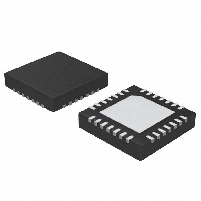
- Part No.:
- MAX1538ETI+
- Manufacturer:
- Analog Devices Inc./Maxim Integrated
- Category:
- Battery Management
- Package:
- 28-WFQFN Exposed Pad
- Datasheet:
-
 MAX1538ETI+.pdf
- Description:
- IC BATT PWR MGMT 28TQFN
- Quantity:
- Payment:

- Shipping:

Inventory:2,702
Please send an inquiry. Send us your inquiry, and we will respond immediately.
Product details
Overview
The MAX1538ETI+ from Maxim Integrated is a dual-battery power-source selector IC that autonomously selects between AC adapter, airline adapter, and two Li-ion battery packs based on presence detection, state-of-charge monitoring, and undervoltage thresholds. It features break-before-make switching (≤0.88 µs transition), direct P-channel MOSFET gate drive (±70 mA sink/source), 50 µA max quiescent current from highest supply, and supports relearn mode for battery capacity calibration. It is used in notebook computers requiring hot-swap-capable, aircraft-compliant power path management.
For engineers reviewing the MAX1538ETI+ datasheet, MAX1538ETI+ pinout, MAX1538ETI+ application, or MAX1538ETI+ equivalent, key selection criteria include its 4.75V–28V ADPIN input range, dual-battery undervoltage detection via MINVA/MINVB inputs, 3.3V linear regulator output (VDD), and open-drain state outputs (OUT0–OUT2) for host µP coordination.
Technical Context
The MAX1538ETI+ implements a fixed-state machine with analog comparators for ACDET (2.0 V ±20 mV threshold) and AIRDET (same threshold, mutually exclusive with ACDET), plus dual independent battery voltage monitors using 5× scaling of MINVA/MINVB reference inputs to detect undervoltage (e.g., 13.0 V trip at VMINVA = 2.6 V). It drives eight P-channel MOSFET gates-ADPPWR, REVBLK, ADPBLK, DISBAT, CHGA, CHGB, DISA, DISB-with clamp-limited turn-on voltages (−3.5 V to −11.7 V relative to source) and sub-microsecond timing (0.3–0.88 µs).
Its architecture separates power-path control from system µP firmware: logic inputs (CHRG, BATSEL, RELRN) enable charge/discharge selection and relearn mode, while three open-drain outputs (OUT0–OUT2) encode eight discrete states per Table 1-including AC charge A/B, relearn A/B, airline mode, and discharge A/B-without requiring real-time polling or interrupt handling.
Key Specifications
| Parameter | Value and Actual Design Meaning |
|---|---|
| Input Voltage Range (ADPIN) | 4.75 V to 28 V - supports wide-range AC adapters including aircraft supplies. |
| VDD Output | 3.3 V ±1% (3.27–3.33 V) - powers internal circuitry and external logic with <1 mV/V PSRR. |
| Quiescent Current (max) | 50 µA from highest supply - enables ultra-low-power battery backup operation. |
| Break-Before-Make Time | ≤0.88 µs - prevents shoot-through during source transitions; ensures safe hot-swap capability. |
| Battery Undervoltage Threshold | Programmable via MINVA/MINVB (0.93–2.6 V); 5× scaling yields 4.65–13.0 V range - prevents deep discharge damage. |
| Gate Drive Capability | ±70 mA sink/source, clamp-limited - directly drives P-MOSFETs without external buffers or level shifters. |
| Operating Temperature | −40°C to +85°C - qualified for industrial and mobile computing environments. |
Pinout & Package
The MAX1538ETI+ is housed in a 28-pin thin QFN package (5 mm × 5 mm, 0.5 mm pitch) with exposed thermal pad. Pin 1 is marked by dot; pins 15 and 21 are no-connect.
| Pin/Terminal | Circuit Role | Design Meaning |
|---|---|---|
| MINVA / MINVB | Battery A/B undervoltage reference input | Set 5× scaled discharge cutoff (e.g., 2.6 V → 13.0 V); bias current <50 nA enables high-impedance divider design. |
| BATSEL | Battery selection control | Logic low = prefer Battery A (charge/discharge); high = prefer Battery B - determines CHGA/CHGB and DISA/DISB activation. |
| RELRN | Relearn mode enable | High = disable AC adapter, force selected battery discharge for capacity calibration - overrides CHRG when active. |
| OUT0 / OUT1 / OUT2 | State encoding outputs | Open-drain, 25 mA sink - decode 8 states (e.g., "110" = AC charge A) per Table 1 for host µP status monitoring. |
| ADPPWR / REVBLK / ADPBLK / DISBAT / CHGA / CHGB / DISA / DISB | P-channel MOSFET gate drivers | Each drives one external FET; clamp-limited turn-on voltage avoids gate overvoltage; matched timing ensures coordinated sequencing. |
| ADPIN / BATA / BATB / BATSUP / EXTLD / CHGIN | Power rail inputs | ADPIN powers ADPPWR driver; BATA/BATB supply DISA/DISB drivers; BATSUP is main IC supply (diode-OR'd); EXTLD powers REVBLK/ADPBLK; CHGIN powers CHGA/CHGB/DISBAT. |
Key Features
| Feature | Design Value |
|---|---|
| Airline adapter detection | Distinguishes airline (VAIRDET > 2 V, VACDET < 2 V) from AC adapter, disabling charging and powering system solely from adapter - meets aviation safety requirements. |
| Break-before-make switching | Hardware-enforced isolation between sources (≤0.88 µs dead time) eliminates risk of backfeeding or short-circuit during hot-swap - no external timing components needed. |
| Direct P-MOSFET drive | Eight integrated gate drivers eliminate need for external level shifters or buffers - reduces BOM count and PCB area in dual-battery systems. |
| Battery relearn mode | Enables coulomb-counting fuel gauges (e.g., MAX1781) to recalibrate capacity by forcing controlled discharge under AC presence - improves long-term runtime accuracy. |
| Low-quiescent-current operation | 50 µA max from highest supply (e.g., ADPIN or BATA) - extends standby time in battery-backed systems without compromising responsiveness. |
Applications
| Notebook Power Management | Aircraft-Compliant Portable Systems |
|---|---|
Use Scenario: Dual-Li-ion notebook with AC adapter, airline power, and hot-swap battery support. IC Role / Device Role / Timing Role: Autonomous power-path selector managing adapter/battery arbitration, undervoltage cutoff, and relearn-mode discharge sequencing. Use Value: Enables seamless AC-to-battery failover with <1 µs break-before-make, eliminating system brownouts during battery swaps. | Use Scenario: Ruggedized tablet used onboard commercial aircraft with regulated 28 V DC supply. IC Role / Device Role / Timing Role: Airline adapter detector and charger blocker - disables all battery charging paths while routing power exclusively from aircraft supply. Use Value: Complies with FAA/EASA regulations prohibiting battery charging during flight via hardware-level AIRDET-based interlock. |
| Dual-Battery Industrial Handheld | Internet Tablet with Extended Runtime |
Use Scenario: Field-service handheld with swappable primary/backup batteries and external dock charger. IC Role / Device Role / Timing Role: Source selector coordinating dock power, primary battery discharge, and backup battery reserve activation. Use Value: Extends operational uptime by enabling automatic fallback to secondary battery upon primary undervoltage (13.0 V cutoff) without µP intervention. | Use Scenario: Consumer tablet supporting both step-down and step-up battery chargers across OEM variants. IC Role / Device Role / Timing Role: Unified power controller compatible with buck-only or buck-boost chargers - adapts gate drive logic via DISBAT inclusion/exclusion per Figure 1 vs. Figure 2. Use Value: Reduces platform fragmentation: single IC supports multiple charger topologies without redesigning power-path layout. |
Equivalent & Alternatives
The following parts are listed as comparable options for similar power-source selector applications.
| Alternative Part | Technical Difference | Application Difference | Selection Advice |
|---|---|---|---|
| MAX1537ETI+ | Single-battery version; lacks BATB, DISB, CHGB, MINVB, and second battery monitoring path. | Only suitable for systems with one battery pack; cannot manage dual-battery priority or relearn B. | Select MAX1537ETI+ only if dual-battery functionality is unnecessary and board space must be minimized. |
| BQ24725ARGER | TI part with integrated ADC, SMBus interface, and programmable thresholds; requires external MCU for state decoding. | Supports more complex battery chemistries and telemetry but adds firmware overhead and communication latency. | Choose BQ24725ARGER when digital configurability and battery parameter reporting outweigh autonomous analog decision speed. |
Compared with MAX1537ETI+, the MAX1538ETI+ adds full dual-battery arbitration and relearn mode; versus BQ24725ARGER, it delivers deterministic, zero-latency source selection without MCU dependency or serial bus timing constraints.
Availability
MAX1538ETI+ is available at Aetrix Electronics and suitable for notebook computers, internet tablets, and dual-battery portable equipment requiring stable component supply, hot-swap reliability, and aircraft-compliant power management.
Supply support for MAX1538ETI+ includes scheduled delivery planning, volume procurement assistance, BOM continuity management, traceable sourcing, and lifecycle availability coordination for OEM customers, industrial embedded developers, connected-device designers, and electronics production programs.
Manufacturer
Maxim Integrated (now part of Analog Devices) designs precision analog, mixed-signal, and power-management ICs for demanding industrial, computing, and automotive applications.
The MAX1538ETI+ belongs to Maxim's battery management and power-path controller product line, engineered specifically for autonomous, multi-source power selection in portable computing platforms with dual-Li-ion battery configurations.
FAQ
What is the function of the RELRN pin on the MAX1538ETI+?
The RELRN pin on the MAX1538ETI+ enables battery relearn mode when driven high. In this mode, the MAX1538ETI+ disables the AC adapter path (via ADPPWR) and forces discharge from the selected battery (A or B, per BATSEL), allowing coulomb-counting fuel gauges to calibrate capacity. RELRN overrides CHRG and is only active when an AC adapter is present.
How does the MAX1538ETI+ detect and respond to airline adapter presence?
The MAX1538ETI+ detects airline adapter presence when VAIRDET exceeds 2.0 V while VACDET remains below 2.0 V. Upon detection, the MAX1538ETI+ disables all battery charging paths (CHGA/CHGB) and powers the system exclusively from the adapter - ensuring compliance with aviation safety regulations that prohibit in-flight battery charging.
What is the purpose of the MINVA and MINVB pins on the MAX1538ETI+?
The MINVA and MINVB pins on the MAX1538ETI+ set the undervoltage cutoff thresholds for Battery A and Battery B, respectively. Each accepts a 0.93–2.6 V reference; the MAX1538ETI+ internally scales this by 5× (e.g., 2.6 V → 13.0 V) to prevent discharge below safe Li-ion levels. Input bias current is <50 nA, enabling high-accuracy resistor-divider design.
Can the MAX1538ETI+ support both step-down and step-up battery chargers?
Yes, the MAX1538ETI+ supports both step-down and step-up/step-down battery chargers. Its DISBAT pin is optional: included for step-up chargers (to disconnect battery during charge) and omitted for step-down chargers. Figures 1 and 2 in the MAX1538ETI+ datasheet show the respective configurations, maintaining identical core selection logic in both cases.
What do the OUT0, OUT1, and OUT2 pins indicate on the MAX1538ETI+?
The OUT0, OUT1, and OUT2 pins on the MAX1538ETI+ are open-drain state outputs encoding eight possible power-path conditions (e.g., "110" = AC charge Battery A). They provide real-time status to the host µP without polling, covering AC charge, relearn, airline, discharge, and idle modes per Table 1 in the MAX1538ETI+ datasheet - enabling efficient power-management firmware.
MAX1538ETI+ Specifications
- Product attributes
- Attribute value
- Manufacturer:
- Analog Devices Inc./Maxim Integrated
- Series:
- -
- Package/Case:
- 28-WFQFN Exposed Pad
- Packaging:
- Tube
- Product Status:
- Active
- Function:
- Power Management
- Battery Chemistry:
- -
- Number of Cells:
- -
- Fault Protection:
- -
- Interface:
- -
- Operating Temperature:
- -40°C ~ 85°C (TA)
- Grade:
- -
- Qualification:
- -
- Mounting Type:
- Surface Mount
- Supplier Device Package:
- 28-TQFN (5x5)
MAX1538ETI+ FAQ
1.How can I place an order for MAX1538ETI+ through Aetrix?
Please submit a Request for Quotation (RFQ) for MAX1538ETI+ on Aetrix. Our sales agent will provide a competitive quotation and guide you through the order confirmation once you accept the terms.
2.Are the price and stock information for MAX1538ETI+ reliable?
The price and inventory of MAX1538ETI+ are updated periodically and may fluctuate due to market conditions. Stock and pricing data are typically refreshed every 24 hours. Quotation validity for MAX1538ETI+ is usually 5 days.
3.What payment methods are accepted for MAX1538ETI+?
We accept Wire Transfer, PayPal, Credit Card, Western Union, MoneyGram, and Escrow for MAX1538ETI+ transactions.
Note: Certain payment methods may incur a processing fee.
4.How is shipping managed for MAX1538ETI+?
MAX1538ETI+ orders can be shipped via leading logistics carriers, including DHL, UPS, FedEx, TNT, or Registered Mail.
Once your MAX1538ETI+ order is processed, you will receive an email with the shipment details and tracking number.
Note: Tracking information may take up to 24 hours to appear. Express delivery typically takes 3–5 business days.
5.How can I obtain technical support or documentation for MAX1538ETI+?
For technical support, including MAX1538ETI+ datasheets, pinout diagrams, or application guidance, please contact our engineering support team. They can provide detailed documentation and assistance for your MAX1538ETI+ requirements.
6.How does Aetrix verify that MAX1538ETI+ is sourced from the original manufacturer or authorized distributors?
All MAX1538ETI+ products on Aetrix are procured from qualified distributors and authorized channels. Our dedicated quality assurance team conducts strict verification, including traceability checks and, if necessary, third-party testing. This ensures that MAX1538ETI+ meets industry standards.
7.What is the process for return or replacement of MAX1538ETI+?
All MAX1538ETI+ units undergo pre-shipment inspection (PSI). If there is an issue with MAX1538ETI+, returns or replacements are accepted under the following conditions:
1.Quantity discrepancies, incorrect items, or visible external defects (such as breakage or corrosion), acknowledged by Aetrix.
2.The issue is reported within 90 days of delivery.
3.The MAX1538ETI+ part is unused and in its original packaging.
Return procedure for MAX1538ETI+:
1.Submit a request within 90 days.
2.Obtain a Return Material Authorization (RMA) from Aetrix.
MAX1538ETI+ Tags

-
BQ29700DSER
Texas Instruments

-
S-8241ABKMC-GBKT2G
ABLIC Inc.
-
S-8241ABPMC-GBPT2G
ABLIC Inc.

-
BQ27427YZFR
Texas Instruments

-
BQ27426YZFR
Texas Instruments

-
STC3117IJT
STMicroelectronics

-
STC3115IJT
STMicroelectronics

-
BQ76925RGER
Texas Instruments
-
NPM1100-QDAA-R
Nordic Semiconductor ASA

-
BQ27441DRZR-G1A
Texas Instruments

-
STC3115AIQT
STMicroelectronics

-
S-8252AAL-M6T1U
ABLIC Inc.
Tech Hub

A practical engineering guide to 3.3V and 5V logic compatibility, input thresholds, resistor dividers, translator ICs, MOSFET level shifting, I2C pull-ups, timing limits and power-sequencing risks.

The 74HC595 uses push-pull logic outputs, while the TPIC6B595 uses 50 V open-drain DMOS sinks for higher-power loads. This guide compares timing, current limits, 3.3 V interfacing, load wiring, thermal…

The 74HC595 converts serial data into eight stable parallel outputs. This guide covers pin functions, shift and storage timing, OE and MR behavior, drive-current limits, cascading, voltage compatibilit…

A technical comparison of level-sensitive latches and edge-triggered flip-flops, covering timing windows, setup and hold limits, master–slave operation, time borrowing, race-through, HDL inference and…

A D latch stores one bit while Enable controls when data can pass. This reference covers gate-level operation, truth tables, transparency, setup and hold timing, LE versus OE, common ICs and practical …

An SR latch stores one bit through cross-coupled feedback. This engineering reference covers NOR and NAND implementations, truth tables, forbidden-state recovery, gated operation, switch debouncing, fa…

Latch circuits retain one bit through feedback. This technical reference covers SR and D latches, truth tables, transparency, timing limits, latch-versus-flip-flop behavior, applications and common log…

An engineering guide to LED driver operation, constant-current and constant-voltage outputs, linear and switching topologies, dimming, IC selection, calculations, replacement compatibility, and fault c…

Operational amplifier guide covering op amp basics, feedback, ideal vs real op amps, common configurations, buffer circuits, offset, bias current, gain-bandwidth, slew rate, rail-to-rail limits and sel…

Jumper cables guide covering safe connection order, red and black clamp placement, final ground connection, cable gauge, length, clamp quality, copper vs CCA cables, jump starter comparison and battery…


