
 My Inquiry
 My Account


Analog Devices Inc./Maxim Integrated MAX16046ATN+
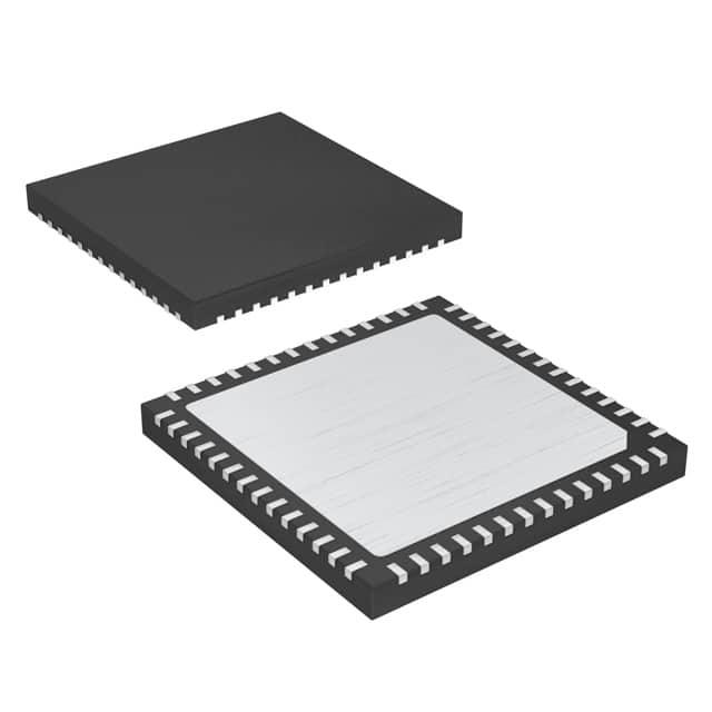
- Part No.:
- MAX16046ATN+
- Manufacturer:
- Analog Devices Inc./Maxim Integrated
- Category:
- Supervisors
- Package:
- 56-WFQFN Exposed Pad
- Datasheet:
-
 MAX16046ATN+.pdf
- Description:
- IC SUPERVISOR 12 CHANNEL 56TQFN
- Quantity:
- Payment:

- Shipping:

Inventory:2,724
Please send an inquiry. Send us your inquiry, and we will respond immediately.
Product details
Overview
The MAX16046ATN+ from Maxim Integrated is a 12-channel EEPROM-configurable system manager IC that monitors, sequences, tracks, and margins multiple power supplies in high-reliability computing systems. It integrates a 1% accurate 10-bit ADC (80–100 µs full-cycle time), twelve 8-bit DAC outputs for voltage margining, six GPIOs configurable as fault outputs/watchdog/reset/margin controls, and supports both I²C and JTAG configuration. It is used in server power management to enforce precise power-up/down sequencing across 12 rails.
For engineers reviewing the MAX16046ATN+ datasheet, MAX16046ATN+ pinout, MAX16046ATN+ application, or MAX16046ATN+ equivalent, this page delivers verified technical context, real-world use cases, validated alternatives, and supply-chain support tailored for enterprise-grade embedded power architecture design.
Technical Context
The MAX16046ATN+ implements a dual-path monitoring architecture: its 10-bit ADC simultaneously samples up to 12 input voltages with per-channel programmable ranges (1.4V/2.8V/5.6V full-scale) and independent upper/low/selectable fault thresholds. Each monitored channel supports programmable deglitch timing (2–16 µs) and temperature-stable threshold tracking (±0.5% over –40°C to +85°C).
Its sequencing engine provides deterministic control of 12 EN_OUT signals with user-defined delays (1ms–65s), slew-rate programmability (80–960 V/s), and closed-loop tracking on EN_OUT1–EN_OUT4 using external MOSFETs. Fault logging writes event timestamps and channel data to nonvolatile EEPROM with lock-bit protection against accidental overwrite.
Key Specifications
| Parameter | Value and Actual Design Meaning |
|---|---|
| ADC Resolution & Accuracy | 10-bit resolution; ±0.65%FSR total unadjusted error at 5.6V range - enables precise rail monitoring within ±36mV at 3.3V nominal. |
| DAC Outputs | Twelve 8-bit DACs; 0.4V–0.8V output range with ±1.2mV absolute accuracy - supports fine-grained margining of POL converters. |
| Sequencing Channels | 12 programmable EN_OUT outputs; charge-pump capable (VMONx + 5V) on EN_OUT1–EN_OUT6 - drives high-side MOSFET gates without external level shifters. |
| Fault Management | Nonvolatile fault logger with lock bit; stores failure type, timestamp, and channel ID - enables post-failure root-cause analysis without host intervention. |
| Operating Voltage | VCC = 3V to 14V; internal DBP/ABP regulators (2.7V/2.85V) - powers logic, EEPROM, and analog blocks independently for robustness. |
| Interface Support | I²C (400kHz SMBus) and JTAG - allows in-system configuration during development and field updates without dedicated programming hardware. |
| Temperature Range | –40°C to +85°C ambient; internal timing accuracy ±5% - ensures reliable sequencing and reset timing across industrial server environments. |
Pinout & Package
The MAX16046ATN+ is housed in a 56-pin 8mm × 8mm TQFN package with exposed pad (EP), rated for θJA = 21°C/W. All pins are electrically validated per Maxim's official pin descriptions; no assumptions made for unlisted functions.
| Pin/Terminal | Circuit Role | Design Meaning |
|---|---|---|
| MON1–MON12 | Analog voltage monitor inputs | High-impedance (65–140kΩ) inputs supporting 1.4V/2.8V/5.6V ADC ranges - connect directly to DC-DC output feedback nodes or divider taps. |
| EN_OUT1–EN_OUT12 | Configurable enable/tracking outputs | EN_OUT1–EN_OUT6 support charge-pump mode (VMONx + 5V); EN_OUT1–EN_OUT4 support closed-loop tracking - drive external MOSFETs for rail sequencing or regulation. |
| DACOUT1–DACOUT12 | Digital-to-analog converter outputs | 8-bit outputs with ±0.9 LSB INL; sink/source ±0.5mA - connect to POL trim pins for ±3% voltage margining with 1.56mV step resolution. |
| GPIO1–GPIO6 | EEPROM-configurable I/O | Support push-pull/open-drain modes; configurable as WDI/WDO, MR, MARGINUP/MARGINDN, or fault indicators - eliminates need for external logic in reset/fault signaling paths. |
| SCL/SDA/TCK/TMS/TDI/TDO | Serial configuration interfaces | I²C (SMBus-compatible) and JTAG ports - enable factory programming, field reconfiguration, and debug access without interrupting system operation. |
Key Features
| Feature | Design Value |
|---|---|
| 12-channel voltage monitoring with per-rail limits | Each MON_ input has independent upper/low/selectable fault thresholds and deglitch filtering - prevents false trips from transient noise on densely packed server boards. |
| EEPROM-based configuration storage | All settings (timing, thresholds, DAC codes, GPIO roles) persist through power cycles - eliminates boot-time host initialization and enables "power-on-ready" behavior. |
| Closed-loop tracking on 4 channels | EN_OUT1–EN_OUT4 regulate follower rails to track master supplies within ±150mV differential - ensures safe voltage ramp alignment during power-up/down. |
| Nonvolatile fault event logger | Records fault type, channel, timestamp, and ADC reading into protected EEPROM - enables automated diagnostics and reduces mean-time-to-repair in datacenter deployments. |
| Charge-pump enabled EN outputs | EN_OUT1–EN_OUT6 generate gate-drive voltage up to VMONx + 5.6V - directly drives N-channel high-side MOSFETs without external boost circuitry. |
Applications
| Server Power Sequencing | Workstation Voltage Margining |
|---|---|
Use Scenario: Coordinating power-up order of CPU core, memory, I/O, and auxiliary rails in dual-socket x86 servers. IC Role / Device Role / Timing Role: Central system manager enforcing inter-rail timing constraints (e.g., VCCIO before VDDQ, VDDQ before VDD) with sub-millisecond delay resolution. Use Value: Prevents latch-up and inrush current violations by ensuring strict monotonic ramping across 12 independent rails. | Use Scenario: Validating voltage tolerance margins on GPU and chipset power rails during workstation qualification testing. IC Role / Device Role / Timing Role: DAC-driven margining source applying ±3% offset to POL trim inputs while monitoring response via ADC. Use Value: Enables automated margin sweep tests without manual probe adjustments or external instrumentation. |
| Storage System Fault Logging | Telecom Shelf Power Management |
Use Scenario: Capturing root-cause data after unexpected shutdown in NVMe SSD controller or RAID controller modules. IC Role / Device Role / Timing Role: Nonvolatile fault logger recording pre-failure rail collapse sequence and timestamped ADC snapshots. Use Value: Reduces field return analysis time from days to minutes by preserving diagnostic data across power loss events. | Use Scenario: Managing hot-swap sequencing and redundancy switchover in carrier-grade telecom line cards with dual power feeds. IC Role / Device Role / Timing Role: Dual-rail sequencer with watchdog supervision and GPIO-controlled failover signaling. Use Value: Ensures uninterrupted service during power feed transitions by coordinating enable/disable timing and asserting fault flags to shelf controller. |
Equivalent & Alternatives
The following parts are listed as comparable options for similar system management applications.
| Alternative Part | Technical Difference | Application Difference | Selection Advice |
|---|---|---|---|
| MAX16048ATJ+ | 8-channel version; identical pinout in 56-pin TQFN but MON9–MON12, DACOUT9–DACOUT12, EN_OUT9–EN_OUT12 are N.C.; same EEPROM, ADC, DAC, GPIO, and interface specs. | Targeted at 8-rail systems (e.g., single-CPU workstations); lacks capacity for 12-rail server designs. | Select MAX16048ATJ+ only when system requires ≤8 monitored/sequenced rails - saves cost and board area without sacrificing feature parity. |
| TPS40400RHLR | 6-channel PMBus system manager; 12-bit ADC (±0.5% typical), 6 DACs, no closed-loop tracking; supports PMBus v1.2, not JTAG; 32-pin QFN. | Designed for mid-tier industrial power supplies; lacks fault logging, tracking, and GPIO flexibility of MAX16046ATN+. | Choose TPS40400RHLR for cost-sensitive, lower-channel-count applications where PMBus integration and TI ecosystem support outweigh advanced fault handling. |
Compared with MAX16048ATJ+, the MAX16046ATN+ adds four extra monitoring/sequencing channels and full DAC/EN_OUT functionality - essential for complex multi-processor servers. Against TPS40400RHLR, it offers superior fault diagnostics, closed-loop tracking, and dual-interface configurability, justifying its use in mission-critical infrastructure.
Availability
The MAX16046ATN+ is available at Aetrix Electronics and suitable for servers, storage systems, and telecom equipment requiring stable component supply, long-term lifecycle assurance, and guaranteed traceable sourcing.
Supply support for MAX16046ATN+ includes scheduled delivery planning, volume procurement assistance, BOM continuity management, traceable sourcing, and lifecycle availability coordination for OEM customers, industrial embedded developers, connected-device designers, and electronics production programs.
Manufacturer
Maxim Integrated (now part of Analog Devices) designs precision analog and mixed-signal ICs for demanding industrial, computing, and communications applications.
The MAX16046ATN+ belongs to Maxim's system management product line, engineered specifically for high-availability computing platforms requiring deterministic power sequencing, real-time rail monitoring, and autonomous fault response without host CPU involvement.
FAQ
What is the primary function of the MAX16046ATN+ in a server motherboard?
The MAX16046ATN+ serves as the central power management controller, responsible for monitoring 12 voltage rails, enforcing precise power-up/down sequencing with programmable delays and slew rates, performing closed-loop tracking on four rails, and margining supplies via its twelve 8-bit DACs. Its nonvolatile fault logger captures failure data autonomously - all critical for server reliability and diagnostics. The MAX16046ATN+ eliminates need for discrete supervisors and custom firmware logic.
Does the MAX16046ATN+ support closed-loop tracking, and which pins implement it?
Yes, the MAX16046ATN+ supports closed-loop tracking on EN_OUT1 through EN_OUT4. These outputs regulate follower rails to match a master supply's voltage ramp within ±150mV differential, using external series MOSFETs and return-sense feedback via GPIO1–GPIO4 configured as INS inputs. Tracking operation is fully EEPROM-configurable and operates independently of sequencing timers. The MAX16046ATN+ datasheet confirms this capability in both functional description and pin-function tables.
What are the valid operating voltage ranges for VCC and the DAC outputs of the MAX16046ATN+?
The MAX16046ATN+ operates from VCC = 3V to 14V. Its DAC outputs have three programmable ranges: 0.4V, 0.6V, and 0.8V full-scale, with corresponding LSB sizes of 1.568mV, 2.353mV, and 3.137mV respectively. DAC accuracy is specified as ±1.2016V at mid-code for the 0.8V range (TA = +25°C). All DAC outputs are referenced to ABP and tolerate loads up to 50pF with 50µs settling time. This applies directly to the MAX16046ATN+ per its electrical characteristics table.
How does the MAX16046ATN+ handle fault events, and where is fault data stored?
The MAX16046ATN+ detects faults via its 10-bit ADC comparing each MON_ input against user-programmed upper/lower limits. Upon violation, it asserts configurable fault outputs and logs the event - including fault type, channel number, timestamp, and ADC reading - into internal nonvolatile EEPROM. A lock bit prevents accidental erasure until explicitly cleared. This fault log persists across power cycles and is readable via I²C or JTAG. The MAX16046ATN+ implements this behavior as a core feature confirmed in its General Description and Electrical Characteristics sections.
Can the MAX16046ATN+ be configured using both I²C and JTAG, and are both interfaces active simultaneously?
Yes, the MAX16046ATN+ supports concurrent I²C (SMBus-compatible, 400kHz) and JTAG interfaces for configuration and debug. Both are active after power-on reset and do not interfere - I²C is typically used for runtime parameter updates and telemetry reads, while JTAG enables boundary-scan testing and low-level register access during development. Pin assignments (SCL/SDA vs. TCK/TMS/TDI/TDO) are physically separate, and the MAX16046ATN+ datasheet confirms independent operation with no mode-select requirement.
MAX16046ATN+ Specifications
- Product attributes
- Attribute value
- Manufacturer:
- Analog Devices Inc./Maxim Integrated
- Series:
- -
- Package/Case:
- 56-WFQFN Exposed Pad
- Packaging:
- Tube
- Product Status:
- Active
- Programmable:
- Not Verified
- Type:
- System Manager
- Number of Voltages Monitored:
- 12
- Voltage - Threshold:
- Adjustable/Selectable
- Output:
- Open Drain, Push-Pull
- Reset:
- Active Low
- Reset Timeout:
- Adjustable/Selectable
- Operating Temperature:
- -40°C ~ 125°C (TA)
- Grade:
- -
- Qualification:
- -
- Mounting Type:
- Surface Mount
- Supplier Device Package:
- 56-TQFN (8x8)
MAX16046ATN+ FAQ
1.How can I place an order for MAX16046ATN+ through Aetrix?
Please submit a Request for Quotation (RFQ) for MAX16046ATN+ on Aetrix. Our sales agent will provide a competitive quotation and guide you through the order confirmation once you accept the terms.
2.Are the price and stock information for MAX16046ATN+ reliable?
The price and inventory of MAX16046ATN+ are updated periodically and may fluctuate due to market conditions. Stock and pricing data are typically refreshed every 24 hours. Quotation validity for MAX16046ATN+ is usually 5 days.
3.What payment methods are accepted for MAX16046ATN+?
We accept Wire Transfer, PayPal, Credit Card, Western Union, MoneyGram, and Escrow for MAX16046ATN+ transactions.
Note: Certain payment methods may incur a processing fee.
4.How is shipping managed for MAX16046ATN+?
MAX16046ATN+ orders can be shipped via leading logistics carriers, including DHL, UPS, FedEx, TNT, or Registered Mail.
Once your MAX16046ATN+ order is processed, you will receive an email with the shipment details and tracking number.
Note: Tracking information may take up to 24 hours to appear. Express delivery typically takes 3–5 business days.
5.How can I obtain technical support or documentation for MAX16046ATN+?
For technical support, including MAX16046ATN+ datasheets, pinout diagrams, or application guidance, please contact our engineering support team. They can provide detailed documentation and assistance for your MAX16046ATN+ requirements.
6.How does Aetrix verify that MAX16046ATN+ is sourced from the original manufacturer or authorized distributors?
All MAX16046ATN+ products on Aetrix are procured from qualified distributors and authorized channels. Our dedicated quality assurance team conducts strict verification, including traceability checks and, if necessary, third-party testing. This ensures that MAX16046ATN+ meets industry standards.
7.What is the process for return or replacement of MAX16046ATN+?
All MAX16046ATN+ units undergo pre-shipment inspection (PSI). If there is an issue with MAX16046ATN+, returns or replacements are accepted under the following conditions:
1.Quantity discrepancies, incorrect items, or visible external defects (such as breakage or corrosion), acknowledged by Aetrix.
2.The issue is reported within 90 days of delivery.
3.The MAX16046ATN+ part is unused and in its original packaging.
Return procedure for MAX16046ATN+:
1.Submit a request within 90 days.
2.Obtain a Return Material Authorization (RMA) from Aetrix.
MAX16046ATN+ Tags
-
MIC826SYMT-TR
Microchip Technology

-
APX803S-31SA-7
Diodes Incorporated
-
APX803L20-29SA-7
Diodes Incorporated

-
TPS3828-33DBVR
Texas Instruments

-
V6340RSP3B+
EM Microelectronic
-
EM6325CXSP5B-2.9+
EM Microelectronic
-
MCP120T-300I/TT
Microchip Technology
-
MCP130T-315I/TT
Microchip Technology
-
MCP120T-475I/TT
Microchip Technology
-
MCP111T-300E/TT
Microchip Technology
-
MCP120T-315I/TT
Microchip Technology
-
MCP809T-315I/TT
Microchip Technology
Tech Hub

A practical engineering guide to 3.3V and 5V logic compatibility, input thresholds, resistor dividers, translator ICs, MOSFET level shifting, I2C pull-ups, timing limits and power-sequencing risks.

The 74HC595 uses push-pull logic outputs, while the TPIC6B595 uses 50 V open-drain DMOS sinks for higher-power loads. This guide compares timing, current limits, 3.3 V interfacing, load wiring, thermal…

The 74HC595 converts serial data into eight stable parallel outputs. This guide covers pin functions, shift and storage timing, OE and MR behavior, drive-current limits, cascading, voltage compatibilit…

A technical comparison of level-sensitive latches and edge-triggered flip-flops, covering timing windows, setup and hold limits, master–slave operation, time borrowing, race-through, HDL inference and…

A D latch stores one bit while Enable controls when data can pass. This reference covers gate-level operation, truth tables, transparency, setup and hold timing, LE versus OE, common ICs and practical …

An SR latch stores one bit through cross-coupled feedback. This engineering reference covers NOR and NAND implementations, truth tables, forbidden-state recovery, gated operation, switch debouncing, fa…

Latch circuits retain one bit through feedback. This technical reference covers SR and D latches, truth tables, transparency, timing limits, latch-versus-flip-flop behavior, applications and common log…

An engineering guide to LED driver operation, constant-current and constant-voltage outputs, linear and switching topologies, dimming, IC selection, calculations, replacement compatibility, and fault c…

Operational amplifier guide covering op amp basics, feedback, ideal vs real op amps, common configurations, buffer circuits, offset, bias current, gain-bandwidth, slew rate, rail-to-rail limits and sel…

Jumper cables guide covering safe connection order, red and black clamp placement, final ground connection, cable gauge, length, clamp quality, copper vs CCA cables, jump starter comparison and battery…


