
 My Inquiry
 My Account


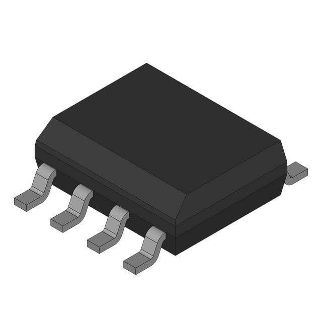
Analog Devices Inc./Maxim Integrated MAX1611CSE-T
- Part No.:
- MAX1611CSE-T
- Manufacturer:
- Analog Devices Inc./Maxim Integrated
- Category:
- Lighting, Ballast Controllers
- Package:
- 16-SOIC (0.154", 3.90mm Width)
- Datasheet:
-
 MAX1611CSE-T.pdf
- Description:
- IC SUPERVISOR CCFL BACKLGT PWR
- Quantity:
- Payment:

- Shipping:

Inventory:5,000
Please send an inquiry. Send us your inquiry, and we will respond immediately.
Product details
Overview
MAX1611CSE-T from Maxim Integrated is a digitally controlled CCFL backlight power supply IC with SMBus 2-wire serial interface, integrated 26V/0.7W power MOSFET, and 5-bit DAC for lamp current regulation. It operates from 4.75V to 26V input, delivers up to 5mA RMS lamp current, and supports isolated transformer-driven CCFLs in notebook displays.
For engineers reviewing the MAX1611CSE-T datasheet, MAX1611CSE-T pinout, MAX1611CSE-T application, or MAX1611CSE-T equivalent, this page provides verified technical context, real-world timing and protection behavior, SMBus register-level control details, and validated alternatives for CCFL brightness management in portable medical and POS display systems.
Technical Context
The MAX1611CSE-T implements current-mode PWM control of an internal N-channel BATT-to-LX switch, regulating CCFL lamp current via feedback from CSAV (averaged voltage) and CC (voltage-to-current converter output). Its analog loop uses a transconductance amplifier driving a capacitor on CC to set regulation bandwidth.
It integrates a 2.0V reference (REF), 4.5V linear regulator (VL), open-tube protection (OTP) comparator referenced to REF, and oscillator synchronization (SYNC) supporting 145kHz/290kHz switching. SMBus interface enables direct 5-bit DAC setting without external counter logic.
Key Specifications
| Parameter | Value and Actual Design Meaning |
|---|---|
| BATT Input Range | 4.75V to 26V - supports wide-input battery-powered systems including 5V, 12V, and 24V rails |
| Switch On-Resistance | 0.7Ω typical - limits conduction loss in internal 26V/0.7W power MOSFET |
| Oscillator Frequency | 145kHz or 290kHz selectable via SYNC pin - enables EMI optimization and transformer size reduction |
| REF Output Voltage | 2.00V ±4% - stable reference for OTP comparator and CSAV regulation point |
| VL Output Voltage | 4.5V in operate mode, 3.6V in shutdown - powers internal logic and external circuitry without separate LDO |
| Quiescent Current | 3mA max operating, 20µA max shutdown - enables low-power display backlighting in battery-critical applications |
| DAC Resolution | 5-bit (32 steps) - provides granular brightness control across full CCFL current range |
Pinout & Package
MAX1611CSE-T is housed in a 16-pin narrow SO package (SOIC-N16), 3.9mm width, 1.27mm pitch, JEDEC MS-012AC compliant.
| Pin/Terminal | Circuit Role | Design Meaning |
|---|---|---|
| BATT (16) | Primary power input | Connects to drain of internal N-MOSFET and input of VL linear regulator; accepts 4.75–26V DC |
| LX (15) | Switch node | Source of internal N-MOSFET; connects to transformer primary center tap in Royer topology |
| BST (14) | Bootstrap supply | Powers high-side gate driver; requires external bootstrap capacitor between BST and LX |
| GND (13) | Analog/digital ground | Common return for all internal circuits; must be low-impedance connection to PCB ground plane |
| VL (12) | Linear regulator output | Provides regulated 4.5V for internal logic and external interface; can be overdriven to 4.75V for +5V system compatibility |
| CS (11) | Current-sense input | Monitors voltage drop across external sense resistor R1; terminates switch cycle when CS > REF − CC |
| OTP (10) | Open-tube protection input | Comparator input referenced to REF; forces switch off if OTP > REF to prevent transformer insulation breakdown |
| REF (9) | 2.0V reference output | Stable 2.00V ±4% reference used by OTP, CSAV regulation, and internal biasing; bypass with 0.1µF to GND |
| SDA (8) | SMBus data I/O | Open-drain bidirectional serial data line; requires external pull-up to VL or 3.3V rail |
| SCL (7) | SMBus clock input | Input-only serial clock; synchronizes data transfer at up to 100kHz standard-mode rate |
| SMBSUS (6) | SMBus suspend select | Selects between two preprogrammed configuration latches (REGSEL=0 or 1); determines standby/shutdown behavior |
| SYNC (5) | Oscillator sync input | Logic-level input: tied to GND/VL → 145kHz; tied to REF → 290kHz; rising edge restarts switch cycle |
| SS (4) | Soft-start control | Internal 4µA current source charges external capacitor; limits peak switch current during startup and dimming transitions |
| CC (3) | Loop compensation | Voltage-to-current converter output; sets CS current limit threshold; capacitor to GND sets regulation bandwidth |
| CSAV (2) | Averaged current sense | Input to transconductance amplifier; voltage averaged from CC via external capacitor; regulates lamp current |
| MINDAC (1) | Minimum DAC scale | Sets lowest CSAV regulation voltage (MINDAC/8); enables 280Hz current chopping when tied to VL |
Key Features
| Feature | Design Value |
|---|---|
| SMBus 2-wire interface | Direct register-level control of 5-bit DAC without external logic; supports dual configuration latches via SMBSUS |
| No-flicker dimming | Internal 280Hz current chopping enabled by MINDAC = VL - eliminates visible flicker at low brightness settings |
| Isolated transformer support | CSAV/CC feedback architecture allows secondary-side lamp drive - improves efficiency and reduces EMI coupling |
| Open/shorted lamp protection | OTP comparator monitors transformer center-tap voltage; disables switch if exceeds REF - prevents insulation failure |
| Selectable switching frequency | 145kHz/290kHz via SYNC pin - enables layout optimization and compliance with EMI standards across product variants |
| Micropower shutdown | 20µA max quiescent current with preserved DAC state - maintains brightness setting across sleep/wake cycles |
Applications
| Medical Display Backlighting | POS Terminal LCD Illumination |
|---|---|
Use Scenario: Portable ultrasound and patient monitor displays requiring flicker-free, low-power CCFL backlighting with precise brightness control. IC Role / Device Role / Timing Role: CCFL current regulator and SMBus-controlled brightness manager; drives Royer oscillator transformer secondary with isolated feedback. Use Value: 5-bit DAC resolution and 280Hz chopping enable smooth dimming down to 3% intensity without perceptible flicker. |
Use Scenario: Compact retail POS terminals with space-constrained LCD backlights needing robust open-lamp fault detection. IC Role / Device Role / Timing Role: Integrated CCFL driver with OTP comparator monitoring transformer center-tap voltage to detect disconnected lamps. Use Value: Prevents transformer insulation breakdown during hot-swap or mechanical failure - extends field reliability beyond 50,000 hours. |
| Notebook Display Inverter | Industrial Instrument Panel Lighting |
Use Scenario: Thin-profile laptop displays powered from 5V–19V battery sources requiring high-efficiency, low-noise backlight drivers. IC Role / Device Role / Timing Role: High-frequency (290kHz) PWM controller with internal 0.7Ω MOSFET and soft-start (SS pin) for inrush current limiting. Use Value: Reduces magnetic component size by 40% vs. 100kHz designs while maintaining >89% power-to-light efficiency. |
Use Scenario: Harsh-environment test equipment with wide-input voltage range (12V–24V) and need for stable CCFL operation under thermal stress. IC Role / Device Role / Timing Role: Temperature-stable 2.0V reference (REF) and VL regulator ensure consistent lamp current regulation from 0°C to +70°C. Use Value: CSAV regulation point drift <±2mV over full temperature range - maintains calibrated brightness in calibration-critical instruments. |
Equivalent & Alternatives
The following parts are listed as comparable options for similar CCFL backlight driver applications.
| Alternative Part | Technical Difference | Application Difference | Selection Advice |
|---|---|---|---|
| MAX1610CSE-T | Digital UP/DN control instead of SMBus; no SDA/SCL/SMBSUS pins; shares identical analog core, pinout except digital interface | Requires external up/down logic or microcontroller GPIO toggling; less suitable for multi-device SMBus networks | Select when board already implements simple push-button or rotary encoder brightness control without bus infrastructure |
| LM3481MM/NOPB | Controller-only (no integrated MOSFET or SMBus); requires external high-voltage MOSFET and discrete DAC/interface | Greater design flexibility but higher BOM count and layout complexity; lacks OTP, REF, VL integration | Select when custom high-voltage switching (>60V) or non-standard lamp topologies (e.g., resonant LLC) are required |
Compared with MAX1610CSE-T, MAX1611CSE-T adds SMBus addressability and dual-configuration latch support but removes UP/DN logic inputs; compared with LM3481MM/NOPB, it integrates power switching, regulation, protection, and digital control in one 16-pin SO package - reducing total solution size by 65% and eliminating 12 external components.
Availability
MAX1611CSE-T is available at Aetrix Electronics and suitable for notebook displays, portable medical equipment, POS terminals, and industrial instrument panels requiring stable component supply and long-term CCFL driver availability.
Supply support for MAX1611CSE-T includes scheduled delivery planning, volume procurement assistance, BOM continuity management, traceable sourcing, and lifecycle availability coordination for OEM customers, industrial embedded developers, connected-device designers, and electronics production programs.
Manufacturer
Maxim Integrated (now part of Analog Devices) is a semiconductor company specializing in precision analog, mixed-signal, and power management ICs for industrial, computing, and consumer applications.
The MAX1610/MAX1611 product line was designed specifically for compact, efficient, digitally controllable CCFL backlighting in portable and space-constrained displays - integrating power switching, regulation, protection, and serial interface in a single SOIC package.
FAQ
What is the function of the SMBSUS pin on the MAX1611CSE-T?
The SMBSUS pin on the MAX1611CSE-T selects between two preprogrammed 7-bit configuration latches. When SMBSUS is low, writes target latch-0 (containing DAC data and shutdown/standby bits); when high, writes target latch-1. This enables dual operational modes - for example, normal brightness and low-power standby - without reprogramming over SMBus. The MAX1611CSE-T retains both latch states independently.
How does the MAX1611CSE-T achieve flicker-free dimming at low brightness levels?
The MAX1611CSE-T achieves flicker-free dimming by enabling internal 280Hz current chopping when the MINDAC pin is tied to VL. This forces periodic on/off cycling of the CCFL at a frequency above human perception threshold, maintaining perceived brightness while avoiding the luminance instability seen in analog current scaling alone. The chopping is synchronized to the internal oscillator and requires no external timing components.
What protection features does the MAX1611CSE-T provide against CCFL faults?
The MAX1611CSE-T provides open-tube protection (OTP) by comparing the voltage on the OTP pin to the internal 2.0V REF. If OTP exceeds REF - indicating excessive transformer secondary voltage due to missing or disconnected lamp - the BATT-to-LX switch is immediately disabled. It also includes shorted-lamp detection via current-sense saturation monitoring on the CS pin, preventing thermal runaway during lamp arc faults.
Can the MAX1611CSE-T operate from a 5V supply, and what is its VL output behavior in that case?
Yes, the MAX1611CSE-T operates from 4.75V minimum, making 5V fully compatible. When BATT = 5V, the VL linear regulator delivers 4.5V at up to 50mA in operate mode and 3.6V in shutdown mode. VL remains active and stable across the full input range, eliminating need for external logic supply - critical for single-rail portable systems. No derating or external boost is required.
What is the role of the CC pin in the MAX1611CSE-T feedback loop?
The CC pin on the MAX1611CSE-T is the output of the voltage-to-current converter that sets the current-limit threshold for the CS pin. The transconductance amplifier compares CSAV voltage to the DAC-set regulation point and sources/sinks current into CC. An external capacitor from CC to GND forms the dominant pole of the regulation loop, directly determining bandwidth - e.g., 1nF yields ~13.5kHz loop bandwidth per the formula BW = 85/(π × C3).
MAX1611CSE-T Specifications
- Product attributes
- Attribute value
- Manufacturer:
- Analog Devices Inc./Maxim Integrated
- Series:
- -
- Package/Case:
- 16-SOIC (0.154", 3.90mm Width)
- Packaging:
- Bulk
- Product Status:
- Active
- Type:
- CCFL Controller
- Frequency:
- 145kHz ~ 290kHz
- Voltage - Supply:
- 4.75V ~ 26V
- Current - Supply:
- 1.5 mA
- Current - Output Source/Sink:
- -
- Dimming:
- No
- Operating Temperature:
- 0°C ~ 70°C (TA)
- Grade:
- -
- Qualification:
- -
- Mounting Type:
- Surface Mount
- Supplier Device Package:
- 16-SOIC
MAX1611CSE-T FAQ
1.How can I place an order for MAX1611CSE-T through Aetrix?
Please submit a Request for Quotation (RFQ) for MAX1611CSE-T on Aetrix. Our sales agent will provide a competitive quotation and guide you through the order confirmation once you accept the terms.
2.Are the price and stock information for MAX1611CSE-T reliable?
The price and inventory of MAX1611CSE-T are updated periodically and may fluctuate due to market conditions. Stock and pricing data are typically refreshed every 24 hours. Quotation validity for MAX1611CSE-T is usually 5 days.
3.What payment methods are accepted for MAX1611CSE-T?
We accept Wire Transfer, PayPal, Credit Card, Western Union, MoneyGram, and Escrow for MAX1611CSE-T transactions.
Note: Certain payment methods may incur a processing fee.
4.How is shipping managed for MAX1611CSE-T?
MAX1611CSE-T orders can be shipped via leading logistics carriers, including DHL, UPS, FedEx, TNT, or Registered Mail.
Once your MAX1611CSE-T order is processed, you will receive an email with the shipment details and tracking number.
Note: Tracking information may take up to 24 hours to appear. Express delivery typically takes 3–5 business days.
5.How can I obtain technical support or documentation for MAX1611CSE-T?
For technical support, including MAX1611CSE-T datasheets, pinout diagrams, or application guidance, please contact our engineering support team. They can provide detailed documentation and assistance for your MAX1611CSE-T requirements.
6.How does Aetrix verify that MAX1611CSE-T is sourced from the original manufacturer or authorized distributors?
All MAX1611CSE-T products on Aetrix are procured from qualified distributors and authorized channels. Our dedicated quality assurance team conducts strict verification, including traceability checks and, if necessary, third-party testing. This ensures that MAX1611CSE-T meets industry standards.
7.What is the process for return or replacement of MAX1611CSE-T?
All MAX1611CSE-T units undergo pre-shipment inspection (PSI). If there is an issue with MAX1611CSE-T, returns or replacements are accepted under the following conditions:
1.Quantity discrepancies, incorrect items, or visible external defects (such as breakage or corrosion), acknowledged by Aetrix.
2.The issue is reported within 90 days of delivery.
3.The MAX1611CSE-T part is unused and in its original packaging.
Return procedure for MAX1611CSE-T:
1.Submit a request within 90 days.
2.Obtain a Return Material Authorization (RMA) from Aetrix.
MAX1611CSE-T Tags
-
HV833MG-G
Microchip Technology
-
HV857MG-G
Microchip Technology
-
MIC4826YMM-TR
Microchip Technology

-
HV823LG-G
Microchip Technology

-
IR2156STRPBF
Infineon Technologies
-
BTS712204ESAXUMA1
Infineon Technologies

-
UC3872DW
Texas Instruments
-
MAX14514ETD+
Analog Devices Inc./Maxim Integrated

-
MAX14521EETG+
Analog Devices Inc./Maxim Integrated
-
HV857LMG-G
Microchip Technology
-
HV860K7-G
Microchip Technology
-
MIC4832YMM
Microchip Technology
Tech Hub

A practical engineering guide to 3.3V and 5V logic compatibility, input thresholds, resistor dividers, translator ICs, MOSFET level shifting, I2C pull-ups, timing limits and power-sequencing risks.

The 74HC595 uses push-pull logic outputs, while the TPIC6B595 uses 50 V open-drain DMOS sinks for higher-power loads. This guide compares timing, current limits, 3.3 V interfacing, load wiring, thermal…

The 74HC595 converts serial data into eight stable parallel outputs. This guide covers pin functions, shift and storage timing, OE and MR behavior, drive-current limits, cascading, voltage compatibilit…

A technical comparison of level-sensitive latches and edge-triggered flip-flops, covering timing windows, setup and hold limits, master–slave operation, time borrowing, race-through, HDL inference and…

A D latch stores one bit while Enable controls when data can pass. This reference covers gate-level operation, truth tables, transparency, setup and hold timing, LE versus OE, common ICs and practical …

An SR latch stores one bit through cross-coupled feedback. This engineering reference covers NOR and NAND implementations, truth tables, forbidden-state recovery, gated operation, switch debouncing, fa…

Latch circuits retain one bit through feedback. This technical reference covers SR and D latches, truth tables, transparency, timing limits, latch-versus-flip-flop behavior, applications and common log…

An engineering guide to LED driver operation, constant-current and constant-voltage outputs, linear and switching topologies, dimming, IC selection, calculations, replacement compatibility, and fault c…

Operational amplifier guide covering op amp basics, feedback, ideal vs real op amps, common configurations, buffer circuits, offset, bias current, gain-bandwidth, slew rate, rail-to-rail limits and sel…

Jumper cables guide covering safe connection order, red and black clamp placement, final ground connection, cable gauge, length, clamp quality, copper vs CCA cables, jump starter comparison and battery…


