
 My Inquiry
 My Account


Analog Devices Inc./Maxim Integrated MAX1625ESE
- Part No.:
- MAX1625ESE
- Manufacturer:
- Analog Devices Inc./Maxim Integrated
- Category:
- Unclassified
- Package:
- Datasheet:
-
 MAX1625ESE.pdf
- Description:
- IC CTRLR HS STPDWN SYNC 16-SOIC
- Quantity:
- Payment:

- Shipping:

Inventory:557
Please send an inquiry. Send us your inquiry, and we will respond immediately.
Product details
Overview
MAX1625ESE from Maxim Integrated is a high-speed, synchronous step-down DC-DC controller optimized for CPU core power delivery in Pentium Pro™, Pentium II™, PowerPC™, Alpha™, and K6™ systems. It delivers over 35A output current from 1.1V to 3.5V with ±1% FB accuracy, 90% efficiency, and resistor-programmable switching frequency (100kHz–1MHz) using external N-channel MOSFETs.
For engineers reviewing the MAX1625ESE datasheet, MAX1625ESE pinout, MAX1625ESE application, or MAX1625ESE equivalent, this page provides verified technical context, confirmed pin functions, real-world transient response behavior, and validated alternative options for CPU VRM designs requiring tight voltage regulation and fast load-step correction.
Technical Context
The MAX1625ESE implements current-mode PWM control with slope compensation, enabling stable operation above 50% duty cycle and >85% maximum duty cycle. Its feedback loop regulates FB to 1.1V via external resistor divider, and it uses CSH/CSL differential inputs for accurate current sensing across an external sense resistor.
It features a dedicated 3.5V ±1% reference output (REF), open-drain power-good signal (PWROK) with ±6%/+8% trip hysteresis, and strong 2A gate drivers (DH/DL) with 0.7Ω typical on-resistance. The BST bootstrap circuit enables high-side N-MOSFET drive without requiring a charge pump IC.
Key Specifications
| Parameter | Value and Actual Design Meaning |
|---|---|
| Output Voltage Range | 1.1V to 3.5V, set by external resistor divider on FB pin - enables precise CPU core rail tuning. |
| FB Accuracy | ±1% over line/load/temperature - ensures stable core voltage under dynamic CPU load changes. |
| Switching Frequency | 100kHz to 1MHz, resistor-programmable via FREQ pin - allows trade-off between inductor size and EMI performance. |
| Max Output Current | Over 35A with proper external MOSFETs and layout - supports high-performance desktop/server CPUs. |
| Efficiency | Up to 90% with synchronous rectification - reduces thermal load and improves system power density. |
| Reference Voltage | 3.5V ±1%, 100µA sink/source capability - usable as system-level analog reference for ADCs or monitoring circuits. |
| PWROK Threshold | FB within −6% to +8% of setpoint - provides robust power sequencing margin for CPU reset logic. |
Pinout & Package
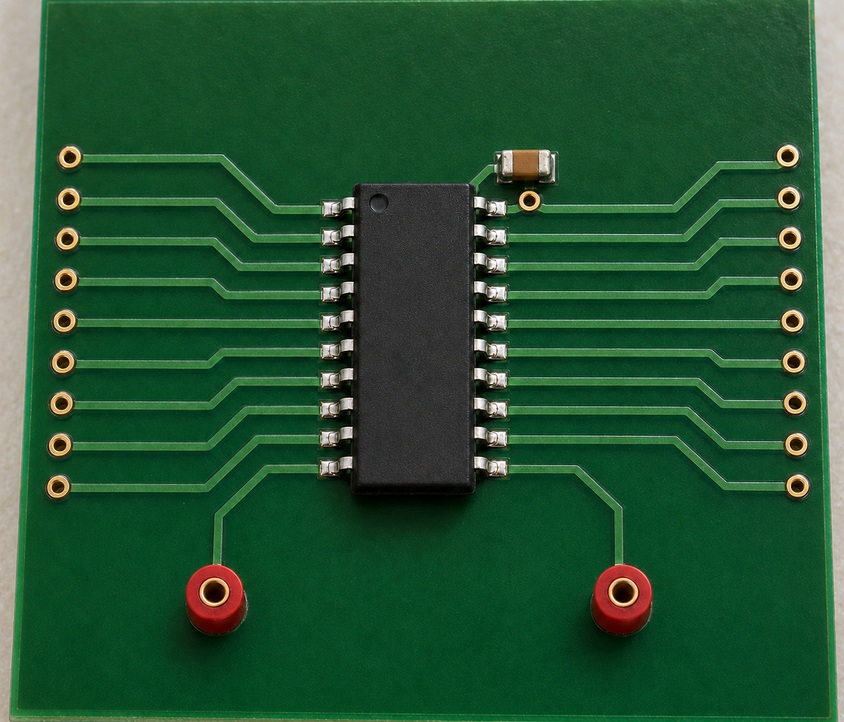
MAX1625ESE is housed in a 16-pin narrow SO package (SOIC-16), 150mil width, -40°C to +85°C operating temperature range.
| Pin/Terminal | Circuit Role | Design Meaning |
|---|---|---|
| VCC | Analog supply input | 5V ±10% analog rail; requires RC filtering per datasheet to suppress noise coupling into control loop. |
| FREQ | Frequency programming input | Resistor-to-AGND sets oscillator frequency; internal 2V bias enables simple R-based configuration. |
| FB | Voltage feedback input | Regulated to 1.1V; connects to output divider - remote sensing not supported (unlike MAX1624). |
| DH | High-side gate driver output | Floating output swinging LX-to-BST; drives external high-side N-MOSFET with 2A peak current. |
| LX | Switching node | Connects to source of high-side MOSFET and inductor - critical for layout low-inductance routing. |
| DL | Low-side gate driver output | Swings PGND-to-VDD; complements DH with 30ns dead time to prevent shoot-through. |
| CSH / CSL | Differential current sense inputs | Measure voltage across external sense resistor; Kelvin connection required for <1% error. |
| PWROK | Open-drain power-good output | Asserts high when FB is within tolerance - interfaces directly with CPU RESET# or sequencer enable. |
| BST | Bootstrap capacitor node | Drives DH gate above LX; requires 0.1µF ceramic + Schottky diode for charge-pump operation. |
| PGND / AGND | Power and analog ground | Separate pins minimize noise coupling; must be joined at single point near device. |
Key Features
| Feature | Design Value |
|---|---|
| Current-mode PWM control | Enables inherent cycle-by-cycle current limiting and stable operation up to >85% duty cycle. |
| Synchronous rectification support | Reduces conduction losses vs. Schottky diodes - essential for >90% efficiency at high current. |
| 3.5V ±1% internal reference | Stable, low-drift reference usable for system monitoring or auxiliary rails without external precision reference. |
| Strong 2A gate drivers | Drives large external MOSFETs with fast edge rates - minimizes switching losses in high-current VRMs. |
| Resistor-programmable frequency | Eliminates need for external clock source or crystal - simplifies BOM and layout for cost-sensitive designs. |
Applications
| Pentium Pro™/Pentium II™ Core Power | GTL Bus Termination |
|---|---|
Use Scenario: Powers CPU core in high-end desktop and workstation motherboards with dynamic voltage scaling requirements. IC Role / Device Role / Timing Role: Primary buck controller regulating VCORE with fast transient response to handle CPU clock gating and burst loads. Use Value: ±1% FB accuracy and GlitchCatcher-free transient response ensure CPU stability during 10A/µs load steps. |
Use Scenario: Supplies regulated 3.3V termination voltage for GTL+ bus signaling in server backplanes and chipset interfaces. IC Role / Device Role / Timing Role: High-current, low-noise DC-DC controller delivering clean 3.3V with minimal ripple for signal integrity. Use Value: 90% efficiency and synchronous rectification reduce heat near sensitive bus traces and improve signal margin. |
| LAN Server VRM | Industrial Computer Power |
Use Scenario: Provides core power to multi-socket server CPUs in rack-mounted LAN servers with strict thermal constraints. IC Role / Device Role / Timing Role: High-current step-down controller driving paralleled MOSFETs for scalable 30A+ output per phase. Use Value: Resistor-programmable frequency allows optimization for low EMI in dense server PCB layouts. |
Use Scenario: Delivers reliable core voltage to embedded industrial CPUs operating in extended temperature environments. IC Role / Device Role / Timing Role: Robust buck controller with -40°C to +85°C rating and integrated protection (UVLO, current limit). Use Value: Internal 3.5V reference supports local ADC monitoring without adding external components. |
Equivalent & Alternatives
The following parts are listed as comparable options for similar step-down controller applications.
| Alternative Part | Technical Difference | Application Difference | Selection Advice |
|---|---|---|---|
| MAX1624EAG | 24-pin SSOP; digital VID interface (D0–D4), GlitchCatcher™, adjustable AC load regulation (0.5%/1%/2%) | Supports Intel VRM-compliant dynamic voltage ID coding; better suited for CPUs requiring VID-based scaling | Select MAX1624EAG when digital voltage programming or enhanced transient response via GlitchCatcher is required. |
| TPS51220ARUKR | 32-pin QFN; integrated MOSFET drivers with adaptive on-time control; 4.5V–24V input; supports 0.5V–5.5V output | Designed for modern mobile/server VRMs with D-CAP2 control and faster transient response than fixed-frequency PWM | Choose TPS51220ARUKR for new designs needing higher integration, wider input range, or improved light-load efficiency. |
Compared with MAX1625ESE, MAX1624EAG adds digital VID and GlitchCatcher for tighter CPU voltage tracking, while TPS51220ARUKR offers integrated control architecture and broader input flexibility - both require PCB redesign due to different packages and pinouts.
Availability
MAX1625ESE is available at Aetrix Electronics and suitable for Pentium Pro™/II™ motherboard designs, GTL bus termination circuits, and industrial computer VRMs requiring stable component supply and long-lifecycle support.
Supply support for MAX1625ESE includes scheduled delivery planning, volume procurement assistance, BOM continuity management, traceable sourcing, and lifecycle availability coordination for OEM customers, industrial embedded developers, connected-device designers, and electronics production programs.
Manufacturer
Maxim Integrated (now part of Analog Devices) is a semiconductor company specializing in high-performance analog, mixed-signal, and power management ICs for computing, communications, and industrial applications.
The MAX1624/MAX1625 product line was designed specifically for high-current, high-precision CPU core power delivery in late-1990s high-end computing platforms - emphasizing ±1% regulation, synchronous rectification, and robust transient handling.
FAQ
What is the function of the LG pin on the MAX1625ESE?
The LG pin is not present on the MAX1625ESE - it is exclusive to the MAX1624EAG variant. MAX1625ESE uses fixed AC load regulation and does not support LG-based loop gain adjustment. This simplifies design but removes the ability to trade off transient response versus output filter size.
Does the MAX1625ESE support remote voltage sensing?
No, the MAX1625ESE does not support remote sensing. Its FB pin is internally regulated to 1.1V and requires a local resistor divider at the output. In contrast, the MAX1624EAG supports remote sensing by connecting FB directly to the CPU's sense point - a key functional distinction between the two variants.
What is the minimum recommended output voltage for the MAX1625ESE?
The minimum output voltage for the MAX1625ESE is 1.1V, as specified in the Electrical Characteristics table and confirmed in the Typical Operating Characteristics plots. Operation below 1.1V is not guaranteed and may violate internal reference and comparator thresholds.
Can the MAX1625ESE be used with a 3.3V input supply?
No - the MAX1625ESE requires a nominal 5V ±10% input (VCC and VDD), as stated in Absolute Maximum Ratings and Electrical Characteristics. A 3.3V supply falls outside its operational range and will prevent proper gate drive, reference generation, and PWM operation.
What is the purpose of the BST pin on the MAX1625ESE?
The BST pin on the MAX1625ESE supplies the floating gate-drive voltage for the high-side N-channel MOSFET. It connects to a bootstrap capacitor charged through an external Schottky diode from VDD, enabling DH to swing above the LX switching node - essential for driving N-MOSFETs in high-side buck configurations.
MAX1625ESE Specifications
- Product attributes
- Attribute value
- Manufacturer:
- Analog Devices Inc./Maxim Integrated
- Series:
- -
- Packaging:
- Tube
- Product Status:
- Obsolete
MAX1625ESE FAQ
1.How can I place an order for MAX1625ESE through Aetrix?
Please submit a Request for Quotation (RFQ) for MAX1625ESE on Aetrix. Our sales agent will provide a competitive quotation and guide you through the order confirmation once you accept the terms.
2.Are the price and stock information for MAX1625ESE reliable?
The price and inventory of MAX1625ESE are updated periodically and may fluctuate due to market conditions. Stock and pricing data are typically refreshed every 24 hours. Quotation validity for MAX1625ESE is usually 5 days.
3.What payment methods are accepted for MAX1625ESE?
We accept Wire Transfer, PayPal, Credit Card, Western Union, MoneyGram, and Escrow for MAX1625ESE transactions.
Note: Certain payment methods may incur a processing fee.
4.How is shipping managed for MAX1625ESE?
MAX1625ESE orders can be shipped via leading logistics carriers, including DHL, UPS, FedEx, TNT, or Registered Mail.
Once your MAX1625ESE order is processed, you will receive an email with the shipment details and tracking number.
Note: Tracking information may take up to 24 hours to appear. Express delivery typically takes 3–5 business days.
5.How can I obtain technical support or documentation for MAX1625ESE?
For technical support, including MAX1625ESE datasheets, pinout diagrams, or application guidance, please contact our engineering support team. They can provide detailed documentation and assistance for your MAX1625ESE requirements.
6.How does Aetrix verify that MAX1625ESE is sourced from the original manufacturer or authorized distributors?
All MAX1625ESE products on Aetrix are procured from qualified distributors and authorized channels. Our dedicated quality assurance team conducts strict verification, including traceability checks and, if necessary, third-party testing. This ensures that MAX1625ESE meets industry standards.
7.What is the process for return or replacement of MAX1625ESE?
All MAX1625ESE units undergo pre-shipment inspection (PSI). If there is an issue with MAX1625ESE, returns or replacements are accepted under the following conditions:
1.Quantity discrepancies, incorrect items, or visible external defects (such as breakage or corrosion), acknowledged by Aetrix.
2.The issue is reported within 90 days of delivery.
3.The MAX1625ESE part is unused and in its original packaging.
Return procedure for MAX1625ESE:
1.Submit a request within 90 days.
2.Obtain a Return Material Authorization (RMA) from Aetrix.
MAX1625ESE Tags

-
936106-1
TE Connectivity AMP Connectors
-
2050030-1
TE Connectivity AMP Connectors
-
1897255-2
TE Connectivity AMP Connectors
-
368811-1
TE Connectivity AMP Connectors
-
2296205-6
TE Connectivity AMP Connectors
-
2232228-1
TE Connectivity AMP Connectors
-
2296207-6
TE Connectivity AMP Connectors
-
2296206-8
TE Connectivity AMP Connectors
-
2316671-2
TE Connectivity AMP Connectors
-
2316671-4
TE Connectivity AMP Connectors
-
2316671-1
TE Connectivity AMP Connectors
-
174463-3
TE Connectivity AMP Connectors
Tech Hub
A D latch stores one bit while Enable controls when data can pass. This reference covers gate-level operation, truth tables, transparency, setup and hold timing, LE versus OE, common ICs and practical …

An SR latch stores one bit through cross-coupled feedback. This engineering reference covers NOR and NAND implementations, truth tables, forbidden-state recovery, gated operation, switch debouncing, fa…

Latch circuits retain one bit through feedback. This technical reference covers SR and D latches, truth tables, transparency, timing limits, latch-versus-flip-flop behavior, applications and common log…

An engineering guide to LED driver operation, constant-current and constant-voltage outputs, linear and switching topologies, dimming, IC selection, calculations, replacement compatibility, and fault c…

Operational amplifier guide covering op amp basics, feedback, ideal vs real op amps, common configurations, buffer circuits, offset, bias current, gain-bandwidth, slew rate, rail-to-rail limits and sel…

Jumper cables guide covering safe connection order, red and black clamp placement, final ground connection, cable gauge, length, clamp quality, copper vs CCA cables, jump starter comparison and battery…

LDO regulator guide covering low dropout voltage, power dissipation, thermal design, PSRR, output noise, capacitor stability, adjustable LDO circuits, LDO vs buck converter and datasheet selection chec…

Conditional Access Module guide covering CAM meaning, CI/CI+ interface, smart card authorization, DVB security workflow, TV and set-top box compatibility, internal electronics, ESD protection, connecto…

Guide to electronic component obsolescence covering EOL risk, PCN/PDN notices, last-time buy planning, replacement options, form-fit-function validation, counterfeit risk and BOM lifecycle management.

18650 battery guide covering lithium-ion cell basics, 3.6V/3.7V voltage, 4.2V charging, mAh and Wh capacity, protected cells, chargers, BMS, series-parallel packs, holders, welding and sourcing checks.…


