
 My Inquiry
 My Account


Analog Devices Inc./Maxim Integrated MAX16823AUE+T
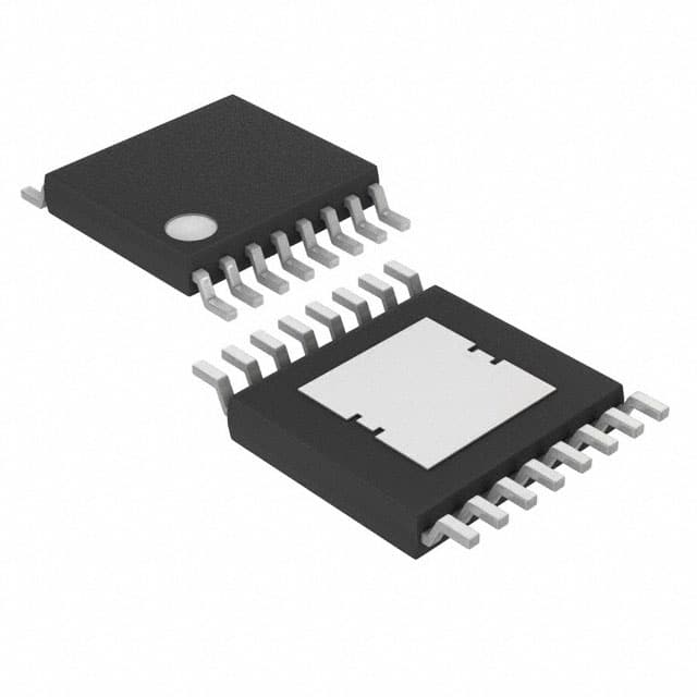
- Part No.:
- MAX16823AUE+T
- Manufacturer:
- Analog Devices Inc./Maxim Integrated
- Category:
- LED Drivers
- Package:
- 16-TSSOP (0.173", 4.40mm Width) Exposed Pad
- Datasheet:
-
 MAX16823AUE+T.pdf
- Description:
- IC LED DRV LIN PWM 100MA 16TSSOP
- Quantity:
- Payment:

- Shipping:

Inventory:3,334
Please send an inquiry. Send us your inquiry, and we will respond immediately.
Product details
Overview
The MAX16823AUE+T from Maxim Integrated is a high-voltage, 3-channel linear LED driver IC designed for automotive exterior lighting. It operates from 5.5V to 40V input, delivers up to 100mA per channel with ±5% current accuracy, features three independent DIM inputs for pulsed dimming, and integrates open-LED detection via the active-low LEDGOOD output-used in rear combination lights (RCLs) and CHMSL systems.
For engineers reviewing the MAX16823AUE+T datasheet, MAX16823AUE+T pinout, MAX16823AUE+T application, or MAX16823AUE+T equivalent, key selection criteria include its -40°C to +125°C automotive temperature rating, 203mV precision current-sense reference, integrated 3.4V/4mA regulator, thermal shutdown at 155°C, and TSSOP-EP package compatibility with load-dump resilience up to 45V.
Technical Context
The MAX16823AUE+T employs linear constant-current regulation per channel using internal pass elements with max 0.7V dropout at 70mA. Each channel's output current is set by an external sense resistor referenced to a factory-trimmed 203mV internal voltage, enabling accurate 5–100mA programming. The device uses analog feedback loops-not switching topology-to maintain stable LED current across wide VIN and temperature ranges.
Its three DIM inputs serve dual roles: logic-level enable/disable control and low-frequency PWM dimming (0–3kHz), while the LGC pin accepts an external capacitor to program LEDGOOD delay timing. The open-drain LEDGOOD output asserts low on open-LED fault or prolonged DIM low condition, and thermal protection disables all outputs above 155°C junction temperature with 23°C hysteresis.
Key Specifications
| Parameter | Value and Actual Design Meaning |
|---|---|
| Input Voltage Range | 5.5V to 40V - supports 12V/24V automotive systems and withstands 45V load-dump transients. |
| Output Current Accuracy | ±5% - guaranteed over -40°C to +125°C, enabling reliable brightness consistency without calibration. |
| Current Sense Reference | 203mV (±10mV) - fixed internal reference used with external resistor to set precise LED current per channel. |
| Dropout Voltage | 0.7V max at 70mA - enables operation with minimal headroom between VIN and LED string forward voltage. |
| Thermal Shutdown | 155°C with 23°C hysteresis - protects against sustained overload or short-circuit conditions via automatic recovery cycling. |
| Regulated Output | 3.4V ±5% @ 4mA - powers auxiliary circuitry (e.g., microcontrollers, sensors) across full input range without external regulator. |
| Dimming Frequency Range | 0–3kHz - supports flexible brightness control including tail/stop dual-level signaling in automotive RCLs. |
| Operating Temperature | -40°C to +125°C - qualified for under-hood and exterior automotive mounting locations. |
Pinout & Package
The MAX16823AUE+T is packaged in a thermally enhanced 16-pin TSSOP-EP (exposed pad) measuring 5mm × 4.4mm, optimized for automotive PCB layouts requiring high power dissipation and EMI robustness.
| Pin/Terminal | Circuit Role | Design Meaning |
|---|---|---|
| OUT1, OUT2, OUT3 | Current-regulated output terminals | Each drives one HB LED string with programmable current; connected directly to LED anodes in high-side configuration. |
| CS1, CS2, CS3 | Current-sense amplifier positive inputs | Low-impedance nodes where external sense resistors connect to GND; regulate current via 203mV reference. |
| DIM1, DIM2, DIM3 | Independent dimming/enable inputs | Active-high logic inputs controlling on/off and PWM dimming per channel; bias current < ±0.1µA minimizes loading. |
| LEDGOOD | Open-LED fault indicator | Open-drain output pulled low on open-circuit detection or extended DIM low; requires external pull-up for system monitoring. |
| LGC | LED fault timing capacitor node | Connects to GND via capacitor (100pF–15nF) to set LEDGOOD delay time (4–6 × 112,000 × CLGC). |
| REG | Integrated 3.4V regulator output | Supplies up to 4mA for auxiliary circuitry; shorting to GND disables thermal shutdown - used for latch-off circuits. |
| IN (pins 7, 8, 9) | Positive supply input | Three parallel pins reduce trace inductance; require local 0.1µF bypass to GND for stability and EMI suppression. |
| GND (pin 12) | Power and signal ground reference | Single ground connection point; exposed pad must be soldered to large-area PCB ground plane for thermal management. |
Key Features
| Feature | Design Value |
|---|---|
| Three-channel independent dimming | Enables simultaneous but distinct brightness control for multi-color (e.g., RGB ambient) or multi-function (e.g., tail/stop) lighting zones. |
| ±5% LED current accuracy over temperature | Eliminates need for channel-specific trimming or closed-loop feedback in production, reducing BOM and test cost. |
| Integrated 3.4V/4mA regulator | Powers microcontroller-based dimming controllers or sensor interfaces directly from VIN, removing external LDO requirement. |
| Open-LED detection with programmable delay | Allows configurable fault response time (via LGC capacitor) to avoid false triggers during transient DIM transitions. |
| Thermal shutdown with hysteresis | Prevents thermal runaway during short-circuit events while enabling automatic recovery once safe temperature is restored. |
| Load-dump tolerant to 45V | Meets ISO 7637-2 Pulse 5a requirements without external TVS, simplifying front-end protection design. |
Applications
| Rear Combination Lights (RCLs) | CHMSL (Center High-Mount Stop Light) |
|---|---|
Use Scenario: Integrated into vehicle rear lamp assemblies to drive brake, tail, turn, and reverse LED strings independently. IC Role / Device Role / Timing Role: Linear constant-current regulator providing precise per-channel current control and open-LED fault reporting via LEDGOOD. Use Value: Enables dual-brightness tail/stop functionality using PWM dimming on DIM inputs and ensures regulatory compliance via fail-safe open-circuit detection. | Use Scenario: Powers high-intensity stop-light LEDs mounted on vehicle parcel shelf, subject to high ambient temperature and vibration. IC Role / Device Role / Timing Role: High-voltage linear driver delivering stable 100mA per channel with thermal shutdown and load-dump immunity. Use Value: Maintains consistent luminance across -40°C to +125°C without derating, and survives 45V transients common in 24V commercial vehicle systems. |
| Automotive Interior RGB Ambient Lighting | Emergency Vehicle Warning Lights |
Use Scenario: Controls red/green/blue LED channels in dashboard or door panel lighting, synchronized to vehicle infotainment commands. IC Role / Device Role / Timing Role: Three independent current-regulated outputs with fast turn-on/turn-off times (≤28µs) for smooth color transitions. Use Value: Supports flicker-free 3kHz PWM dimming for human-perceptible color blending, with ±5% channel matching ensuring accurate white-point tuning. | Use Scenario: Drives high-brightness strobe or rotating beacon LEDs in police, fire, and ambulance lighting systems. IC Role / Device Role / Timing Role: Robust linear driver handling rapid on/off cycling and high peak currents via external BJT boost (up to 2A). Use Value: Delivers reliable flash timing with sub-30µs output response and built-in short-circuit protection to survive wiring faults in field-deployed equipment. |
Equivalent & Alternatives
The following parts are listed as comparable options for similar 3-channel linear LED driver applications.
| Alternative Part | Technical Difference | Application Difference | Selection Advice |
|---|---|---|---|
| MAX16823ATE+T | TQFN-EP package (5mm × 5mm); lower thermal resistance (33.3mW/°C derating) vs. TSSOP-EP (26.1mW/°C). | Better suited for space-constrained or higher-power-density designs requiring enhanced heat dissipation. | Select MAX16823ATE+T when PCB layout allows smaller footprint and thermal performance is critical; MAX16823AUE+T preferred for legacy TSSOP-compatible footprints. |
| TPS92633QPWPRQ1 | Three-channel linear driver with 60V abs max rating, ±3% current accuracy, and integrated diagnostics (I²C interface). | Supports diagnostic readback and configuration via I²C, unlike MAX16823AUE+T's analog-only control. | Choose TPS92633QPWPRQ1 for systems requiring fault logging or dynamic current adjustment; MAX16823AUE+T remains optimal for cost-sensitive, analog-dimming-only automotive lighting. |
Compared with MAX16823ATE+T, the MAX16823AUE+T trades slightly higher thermal resistance for broader board-level compatibility with standard TSSOP land patterns; versus TPS92633QPWPRQ1, it offers simpler implementation and lower BOM count where digital diagnostics are unnecessary.
Availability
The MAX16823AUE+T is available at Aetrix Electronics and suitable for automotive exterior lighting, interior ambient lighting, emergency warning systems, and marine navigation indicators requiring stable component supply across extended temperature and voltage ranges.
Supply support for MAX16823AUE+T includes scheduled delivery planning, volume procurement assistance, BOM continuity management, traceable sourcing, and lifecycle availability coordination for OEM customers, industrial embedded developers, connected-device designers, and electronics production programs.
Manufacturer
Maxim Integrated, now part of Analog Devices, designs precision analog, mixed-signal, and power management ICs for automotive, industrial, and communications markets.
The MAX16823 product line delivers high-voltage, multi-channel linear LED drivers optimized for automotive lighting safety and reliability-specifically targeting rear lamps, CHMSL, and interior ambient systems with stringent AEC-Q100 compliance and load-dump resilience.
FAQ
What is the maximum output current per channel for the MAX16823AUE+T?
The MAX16823AUE+T delivers up to 100mA per channel under normal operation. With an external BJT configured as shown in Figure 5 of the datasheet, it supports output currents up to 2A per channel. This extended capability requires careful thermal design and verification of voltage headroom (VIN > VBE + VFT + VCS_ + VDO). The MAX16823AUE+T's internal pass elements are rated for ≤100mA continuous per channel without external boosting.
Does the MAX16823AUE+T support PWM dimming, and what is its frequency range?
Yes, the MAX16823AUE+T supports pulsed dimming via its three independent DIM inputs, with a specified frequency range of 0–3kHz. Each DIM input functions as both an enable signal and a PWM control input, allowing independent brightness adjustment per channel. The device achieves fast response with ≤28µs turn-on time and ≤18µs turn-off time, making it suitable for flicker-free dimming in automotive lighting applications. The MAX16823AUE+T does not include internal clock generation - external PWM sources must drive the DIM pins directly.
How does the LEDGOOD output function, and what triggers it?
The LEDGOOD output of the MAX16823AUE+T is an active-low, open-drain signal that goes low under two conditions: (1) detection of an open LED string in any of the three channels, or (2) if any DIM input remains low longer than the programmed LEDGOOD delay time (set by capacitor on LGC pin). The delay is calculated as 4×tCK to 6×tCK, where tCK = 112,000 × CLGC. During thermal shutdown, LEDGOOD also asserts low. The MAX16823AUE+T requires an external pull-up resistor on LEDGOOD to interface with microcontroller GPIO or fault-monitoring circuits.
What is the purpose of the REG pin on the MAX16823AUE+T, and what happens if it is shorted to ground?
The REG pin on the MAX16823AUE+T provides a regulated 3.4V ±5% output capable of sourcing up to 4mA for auxiliary circuitry such as microcontrollers, comparators, or level-shifters. A 0.1µF capacitor must be placed between REG and GND for stability. Critically, shorting REG to ground disables the thermal shutdown function - this behavior is documented in the datasheet Note 4 and is leveraged in latch-off circuits (Figure 3) where fault-induced shutdown must persist until power cycle. The MAX16823AUE+T's REG output remains functional across the full 5.5V–40V input range.
Can the MAX16823AUE+T operate in automotive environments with load-dump transients?
Yes, the MAX16823AUE+T is explicitly designed for automotive use and withstands load-dump transients up to 45V, exceeding ISO 7637-2 Pulse 5a requirements for 12V systems. Its absolute maximum input rating is +45V, and it incorporates undervoltage lockout (UVLO) with 4.4V–5.4V hysteresis to prevent malfunction during cold-crank conditions. The device is qualified for the -40°C to +125°C automotive temperature range and features integrated short-circuit and thermal protections. The MAX16823AUE+T's robustness makes it suitable for rear combination lights, CHMSL, and other exterior lighting modules exposed to harsh vehicle electrical environments.
MAX16823AUE+T Specifications
- Product attributes
- Attribute value
- Manufacturer:
- Analog Devices Inc./Maxim Integrated
- Series:
- -
- Package/Case:
- 16-TSSOP (0.173", 4.40mm Width) Exposed Pad
- Packaging:
- Tape & Reel (TR)
- Product Status:
- Active
- Type:
- Linear
- Topology:
- -
- Internal Switch(s):
- Yes
- Number of Outputs:
- 3
- Voltage - Supply (Min):
- 5.5V
- Voltage - Supply (Max):
- 40V
- Voltage - Output:
- 39.3V
- Current - Output / Channel:
- 100mA
- Frequency:
- -
- Dimming:
- PWM
- Applications:
- Backlight, Lighting
- Operating Temperature:
- -40°C ~ 125°C (TA)
- Grade:
- Automotive
- Qualification:
- -
- Mounting Type:
- Surface Mount
- Supplier Device Package:
- 16-TSSOP-EP
MAX16823AUE+T FAQ
1.How can I place an order for MAX16823AUE+T through Aetrix?
Please submit a Request for Quotation (RFQ) for MAX16823AUE+T on Aetrix. Our sales agent will provide a competitive quotation and guide you through the order confirmation once you accept the terms.
2.Are the price and stock information for MAX16823AUE+T reliable?
The price and inventory of MAX16823AUE+T are updated periodically and may fluctuate due to market conditions. Stock and pricing data are typically refreshed every 24 hours. Quotation validity for MAX16823AUE+T is usually 5 days.
3.What payment methods are accepted for MAX16823AUE+T?
We accept Wire Transfer, PayPal, Credit Card, Western Union, MoneyGram, and Escrow for MAX16823AUE+T transactions.
Note: Certain payment methods may incur a processing fee.
4.How is shipping managed for MAX16823AUE+T?
MAX16823AUE+T orders can be shipped via leading logistics carriers, including DHL, UPS, FedEx, TNT, or Registered Mail.
Once your MAX16823AUE+T order is processed, you will receive an email with the shipment details and tracking number.
Note: Tracking information may take up to 24 hours to appear. Express delivery typically takes 3–5 business days.
5.How can I obtain technical support or documentation for MAX16823AUE+T?
For technical support, including MAX16823AUE+T datasheets, pinout diagrams, or application guidance, please contact our engineering support team. They can provide detailed documentation and assistance for your MAX16823AUE+T requirements.
6.How does Aetrix verify that MAX16823AUE+T is sourced from the original manufacturer or authorized distributors?
All MAX16823AUE+T products on Aetrix are procured from qualified distributors and authorized channels. Our dedicated quality assurance team conducts strict verification, including traceability checks and, if necessary, third-party testing. This ensures that MAX16823AUE+T meets industry standards.
7.What is the process for return or replacement of MAX16823AUE+T?
All MAX16823AUE+T units undergo pre-shipment inspection (PSI). If there is an issue with MAX16823AUE+T, returns or replacements are accepted under the following conditions:
1.Quantity discrepancies, incorrect items, or visible external defects (such as breakage or corrosion), acknowledged by Aetrix.
2.The issue is reported within 90 days of delivery.
3.The MAX16823AUE+T part is unused and in its original packaging.
Return procedure for MAX16823AUE+T:
1.Submit a request within 90 days.
2.Obtain a Return Material Authorization (RMA) from Aetrix.
MAX16823AUE+T Tags

-
BCR402RE6327HTSA1
Infineon Technologies

-
BCR430UXTSA2
Infineon Technologies

-
BCR420UE6433HTMA1
Infineon Technologies
-
BCR420UE6327HTSA1
Infineon Technologies
-
BCR421UE6327HTSA1
Infineon Technologies

-
LYT1604D-TL
Power Integrations

-
HV9910CLG-G
Microchip Technology

-
CL2N8-G
Microchip Technology

-
BCR420UW6-7
Diodes Incorporated
-
BCR421UW6-7
Diodes Incorporated

-
BCR420UFD-7
Diodes Incorporated
-
BCR421UFD-7
Diodes Incorporated
Tech Hub

A practical engineering guide to 3.3V and 5V logic compatibility, input thresholds, resistor dividers, translator ICs, MOSFET level shifting, I2C pull-ups, timing limits and power-sequencing risks.

The 74HC595 uses push-pull logic outputs, while the TPIC6B595 uses 50 V open-drain DMOS sinks for higher-power loads. This guide compares timing, current limits, 3.3 V interfacing, load wiring, thermal…

The 74HC595 converts serial data into eight stable parallel outputs. This guide covers pin functions, shift and storage timing, OE and MR behavior, drive-current limits, cascading, voltage compatibilit…

A technical comparison of level-sensitive latches and edge-triggered flip-flops, covering timing windows, setup and hold limits, master–slave operation, time borrowing, race-through, HDL inference and…

A D latch stores one bit while Enable controls when data can pass. This reference covers gate-level operation, truth tables, transparency, setup and hold timing, LE versus OE, common ICs and practical …

An SR latch stores one bit through cross-coupled feedback. This engineering reference covers NOR and NAND implementations, truth tables, forbidden-state recovery, gated operation, switch debouncing, fa…

Latch circuits retain one bit through feedback. This technical reference covers SR and D latches, truth tables, transparency, timing limits, latch-versus-flip-flop behavior, applications and common log…

An engineering guide to LED driver operation, constant-current and constant-voltage outputs, linear and switching topologies, dimming, IC selection, calculations, replacement compatibility, and fault c…

Operational amplifier guide covering op amp basics, feedback, ideal vs real op amps, common configurations, buffer circuits, offset, bias current, gain-bandwidth, slew rate, rail-to-rail limits and sel…

Jumper cables guide covering safe connection order, red and black clamp placement, final ground connection, cable gauge, length, clamp quality, copper vs CCA cables, jump starter comparison and battery…


