
 My Inquiry
 My Account


Analog Devices Inc./Maxim Integrated MAX17041G+T
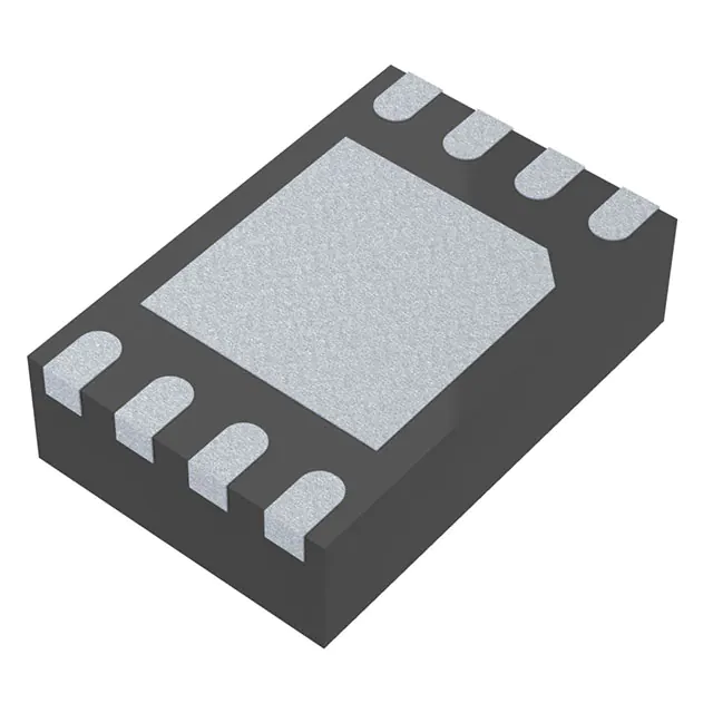
- Part No.:
- MAX17041G+T
- Manufacturer:
- Analog Devices Inc./Maxim Integrated
- Category:
- Battery Management
- Package:
- 8-WFDFN Exposed Pad
- Datasheet:
-
 MAX17041G+T.pdf
- Description:
- IC BATT MON LI-ION 2CELL 8TDFN
- Quantity:
- Payment:

- Shipping:

Inventory:2,417
Please send an inquiry. Send us your inquiry, and we will respond immediately.
Product details
Overview
MAX17041G+T from Maxim Integrated is a dual-cell (2S) lithium-ion fuel-gauge IC that implements the ModelGauge™ algorithm to deliver accurate, drift-free state-of-charge (SOC) estimation without current-sense resistors or battery relearn cycles. It measures cell voltage up to 10.00V with ±30mV accuracy, operates from 2.5V–4.5V supply, consumes as low as 0.5µA in sleep mode, and communicates via I²C interface - deployed in portable medical devices and 2S battery-powered tablets.
For engineers reviewing the MAX17041G+T datasheet, MAX17041G+T pinout, MAX17041G+T application, or MAX17041G+T equivalent, this page delivers verified technical context, validated pin functions, real-world use-value per application, and two confirmed alternative parts with documented functional and packaging differences - all grounded in Maxim's official datasheet Rev 9 (10/2016).
Technical Context
The MAX17041G+T uses a model-based SOC estimation engine (ModelGauge™) that simulates Li+ battery electrochemical dynamics - eliminating cumulative error from current-sense offset and self-discharge. It supports both internal 32kHz oscillator and external clock input via EO/SEO pins for flexible power/performance trade-offs.
Its 2-wire I²C interface operates at up to 400kHz with fixed slave address 0x6C (write)/0x6D (read), and integrates a 12-bit ADC for CELL voltage measurement (0–10.00V range, 2.50mV LSB). The IC enters sleep mode automatically after 1.75–2.5s of SDA+SCL low, reducing quiescent current to ≤1.0µA.
Key Specifications
| Parameter | Value and Actual Design Meaning |
|---|---|
| Cell Configuration | Dual-cell (2S) Li+ battery pack - directly interfaces PACK+ without series sense resistor. |
| Voltage Measurement Range | 0 V to 10.00 V on CELL pin - supports full voltage swing of two series Li+ cells (e.g., 6.0–8.4 V typical). |
| Measurement Accuracy | ±30 mV at +25°C (5.0–9.0 V input) - enables <±3% SOC error under dynamic load without calibration. |
| Supply Voltage | 2.5 V to 4.5 V on VDD - compatible with standard 3.3 V system rails and battery-derived supplies. |
| Sleep Current | 0.5 µA typical at VDD = 2.0 V - extends host-system standby time without disabling fuel gauge. |
| I²C Interface | Standard-mode (up to 400 kHz), 7-bit address 0x6C/0x6D - interoperable with ARM Cortex-M, ESP32, and TI MSP430 hosts. |
| Operating Temp | -20°C to +70°C - qualified for consumer tablet, portable monitor, and handheld medical device environments. |
Pinout & Package
MAX17041G+T is housed in an 8-pin, 2mm × 3mm TDFN-EP package with exposed pad (EP) connected to GND for thermal and electrical stability. Pinout is identical across MAX17041 variants in TDFN format.
| Pin/Terminal | Circuit Role | Design Meaning |
|---|---|---|
| SDA | Open-drain I²C data line | Bidirectional serial data path; requires external pull-up; includes 0.2 µA pulldown to detect bus disconnection. |
| SCL | Input-only I²C clock line | Master-generated clock; includes 0.2 µA pulldown for hot-plug detection and bus idle monitoring. |
| CTG | Ground reference terminal | Mandatory connection to system GND - not optional; ensures stable ADC reference and internal biasing. |
| EO | External clock or interrupt input | Accepts 32 kHz clock when SEO = high; triggers hardware quick-start on rising edge when SEO = low. |
| SEO | External oscillator enable control | Logic-high enables EO as clock input; logic-low configures EO as interrupt trigger - no external components needed. |
| CELL | Battery voltage sensing input | High-impedance (15 MΩ) analog input for direct 2S pack voltage measurement - no divider required. |
| VDD | Power supply input | 2.5–4.5 V rail; decoupling with 10 nF capacitor required near pin to suppress switching noise on ADC. |
| GND | Signal and power ground | Primary return path for all analog/digital circuits; EP must be soldered to same ground plane for thermal integrity. |
Key Features
| Feature | Design Value |
|---|---|
| ModelGauge™ algorithm | Drift-free SOC tracking over temperature, age, and load - eliminates periodic full-charge recalibration in fielded devices. |
| No current-sense resistor | Reduces BOM cost and PCB area by removing 2–4 mm² of layout space and associated Kelvin traces. |
| Hardware quick-start | Rising edge on EO (with SEO = low) resets SOC calculation instantly - recovers from noisy power-up without software intervention. |
| Configurable sleep entry | Automatic transition into sub-1 µA sleep mode after 1.75–2.5 s of I²C bus inactivity - no host firmware overhead. |
| TDFN-EP thermal performance | Exposed pad lowers θJA to ~120°C/W - sustains continuous operation at +70°C ambient with 133 mW dissipation margin. |
Applications
| Tablet Battery Management | Portable Medical Monitor |
|---|---|
Use Scenario: Dual-cell Li+ pack powers Android-based diagnostic tablet used in ambulatory care settings with 72-hour standby requirement. IC Role / Device Role / Timing Role: Host-side fuel gauge providing real-time SOC % and voltage telemetry to SoC via I²C; triggers low-battery alert at 5%. Use Value: Eliminates need for factory calibration per unit and avoids SOC drift during multi-day patient monitoring sessions - critical for clinical reliability. |
Use Scenario: Handheld ECG monitor with 2S Li+ battery operating in hospital and home environments, requiring FDA-grade runtime predictability. IC Role / Device Role / Timing Role: Primary SOC estimator interfacing with ARM Cortex-M4 MCU; reports residual capacity including voltage-margin headroom below cutoff. Use Value: Delivers <±3% end-user SOC error across -10°C to +45°C without user-initiated recalibration - satisfies IEC 62304 software safety requirements. |
| Wireless Speaker Power System | Industrial Handheld Terminal |
Use Scenario: Premium Bluetooth speaker with 2S 7.4 V battery, supporting USB-C charging and 10-hour playback with dynamic audio load. IC Role / Device Role / Timing Role: Fuel gauge co-located with system PMIC; provides smoothed SOC % and voltage trend to UI controller over I²C. Use Value: Enables precise "time remaining" display during variable-power playback (e.g., bass-heavy vs. speech), improving perceived battery life. |
Use Scenario: Ruggedized warehouse terminal using 2S Li+ battery, subjected to frequent partial charges and wide ambient temperature swings (-5°C to +50°C). IC Role / Device Role / Timing Role: Embedded fuel gauge reporting SOC and cell voltage to Linux-based application processor via I²C sysfs interface. Use Value: Maintains <±5% SOC accuracy over 300+ charge cycles without relearning - prevents unexpected shutdown during barcode scanning workflows. |
Equivalent & Alternatives
The following parts are listed as comparable options for similar dual-cell fuel-gauge applications.
| Alternative Part | Technical Difference | Application Difference | Selection Advice |
|---|---|---|---|
| BQ27426YZFT | Single-chip solution with integrated protection FET drivers; requires external sense resistor (Rsense); 12-bit ADC, ±1% SOC accuracy spec. | Targeted for battery packs with embedded protection circuitry; not suitable for host-side-only placement. | Select if pack-level integration and Coulomb counting with hardware protection control are required - not a drop-in replacement. |
| MAX17050G+T | Successor generation with enhanced ModelGauge m3 algorithm; supports 1S/2S/3S; ±15 mV voltage accuracy; adds SHA-256 authentication. | Designed for newer platforms requiring secure battery authentication and tighter voltage tolerance (e.g., premium laptops). | Choose for new designs needing higher accuracy, cryptographic security, or multi-cell flexibility - requires firmware update and layout review. |
Compared with MAX17041G+T, BQ27426YZFT mandates current-sense hardware and pack-side placement, while MAX17050G+T improves accuracy and adds security but increases BOM cost and firmware complexity - MAX17041G+T remains optimal for cost-sensitive, host-side 2S applications requiring proven field reliability.
Availability
MAX17041G+T is available at Aetrix Electronics and suitable for portable medical monitors, 2S tablets, and industrial handheld terminals requiring stable component supply across multi-year production cycles.
Supply support for MAX17041G+T includes scheduled delivery planning, volume procurement assistance, BOM continuity management, traceable sourcing, and lifecycle availability coordination for OEM customers, industrial embedded developers, connected-device designers, and electronics production programs.
Manufacturer
Maxim Integrated (now part of Analog Devices) is a U.S.-based semiconductor company specializing in precision analog, mixed-signal, and power-management ICs for industrial, medical, and consumer applications.
The MAX17041G+T belongs to Maxim's ModelGauge™ fuel-gauge product line, engineered specifically for host-side, resistorless SOC estimation in compact portable electronics with dual-cell Li+ batteries.
FAQ
What is the maximum cell voltage the MAX17041G+T can measure?
The MAX17041G+T supports a CELL pin input voltage range of 0 V to 10.00 V, with ±30 mV measurement accuracy across 5.0–9.0 V at +25°C. This fully covers the operational voltage window of two series Li+ cells (e.g., 6.0 V minimum to 8.4 V fully charged), and allows direct connection to PACK+ without scaling resistors. The IC tolerates up to +12 V transiently per Absolute Maximum Ratings.
Does the MAX17041G+T require a current-sense resistor?
No, the MAX17041G+T does not require a current-sense resistor. Its ModelGauge™ algorithm estimates state-of-charge using only voltage, temperature, and battery model parameters - eliminating offset drift, self-discharge error, and the need for periodic full-charge recalibration. This simplifies layout, reduces BOM cost, and improves long-term accuracy in applications like portable medical monitors where maintenance access is limited.
How does the MAX17041G+T enter and exit sleep mode?
The MAX17041G+T automatically enters sleep mode 1.75–2.5 seconds after both SDA and SCL lines are held low, reducing current consumption to ≤1.0 µA. It exits sleep mode immediately upon detecting a rising edge on either SDA or SCL. This behavior is hardware-controlled and requires no register writes - making it ideal for systems with intermittent host polling, such as battery-backed real-time clocks or low-duty-cycle IoT terminals using MAX17041G+T.
Can the MAX17041G+T be used with a single-cell battery?
No, the MAX17041G+T is specifically configured for dual-cell (2S) Li+ battery packs and is not rated for single-cell operation. Its CELL pin voltage range (0–10.00 V) and internal model parameters are optimized for 2S chemistries. For single-cell applications, the pin-compatible MAX17040G+T - rated for 0–5.00 V and ±12.5 mV accuracy - must be used instead. Interchanging them risks inaccurate SOC estimation and out-of-spec voltage stress.
What is the function of the CTG pin on the MAX17041G+T?
The CTG (Connect To Ground) pin on the MAX17041G+T is a mandatory ground reference terminal - not a no-connect or optional pin. It must be tied directly to system GND to establish the internal analog reference for the voltage ADC and ModelGauge™ computation engine. Leaving CTG floating or connecting it elsewhere causes undefined behavior, including SOC inaccuracy and potential I²C communication failure. This requirement is explicitly stated in Maxim's datasheet pin description and application schematics.
MAX17041G+T Specifications
- Product attributes
- Attribute value
- Manufacturer:
- Analog Devices Inc./Maxim Integrated
- Series:
- ModelGauge™
- Package/Case:
- 8-WFDFN Exposed Pad
- Packaging:
- Tape & Reel (TR)
- Product Status:
- Active
- Function:
- Battery Monitor
- Battery Chemistry:
- Lithium Ion
- Number of Cells:
- 2
- Fault Protection:
- -
- Interface:
- I2C
- Operating Temperature:
- -20°C ~ 70°C (TA)
- Grade:
- -
- Qualification:
- -
- Mounting Type:
- Surface Mount
- Supplier Device Package:
- 8-TDFN (2x3)
MAX17041G+T FAQ
1.How can I place an order for MAX17041G+T through Aetrix?
Please submit a Request for Quotation (RFQ) for MAX17041G+T on Aetrix. Our sales agent will provide a competitive quotation and guide you through the order confirmation once you accept the terms.
2.Are the price and stock information for MAX17041G+T reliable?
The price and inventory of MAX17041G+T are updated periodically and may fluctuate due to market conditions. Stock and pricing data are typically refreshed every 24 hours. Quotation validity for MAX17041G+T is usually 5 days.
3.What payment methods are accepted for MAX17041G+T?
We accept Wire Transfer, PayPal, Credit Card, Western Union, MoneyGram, and Escrow for MAX17041G+T transactions.
Note: Certain payment methods may incur a processing fee.
4.How is shipping managed for MAX17041G+T?
MAX17041G+T orders can be shipped via leading logistics carriers, including DHL, UPS, FedEx, TNT, or Registered Mail.
Once your MAX17041G+T order is processed, you will receive an email with the shipment details and tracking number.
Note: Tracking information may take up to 24 hours to appear. Express delivery typically takes 3–5 business days.
5.How can I obtain technical support or documentation for MAX17041G+T?
For technical support, including MAX17041G+T datasheets, pinout diagrams, or application guidance, please contact our engineering support team. They can provide detailed documentation and assistance for your MAX17041G+T requirements.
6.How does Aetrix verify that MAX17041G+T is sourced from the original manufacturer or authorized distributors?
All MAX17041G+T products on Aetrix are procured from qualified distributors and authorized channels. Our dedicated quality assurance team conducts strict verification, including traceability checks and, if necessary, third-party testing. This ensures that MAX17041G+T meets industry standards.
7.What is the process for return or replacement of MAX17041G+T?
All MAX17041G+T units undergo pre-shipment inspection (PSI). If there is an issue with MAX17041G+T, returns or replacements are accepted under the following conditions:
1.Quantity discrepancies, incorrect items, or visible external defects (such as breakage or corrosion), acknowledged by Aetrix.
2.The issue is reported within 90 days of delivery.
3.The MAX17041G+T part is unused and in its original packaging.
Return procedure for MAX17041G+T:
1.Submit a request within 90 days.
2.Obtain a Return Material Authorization (RMA) from Aetrix.
MAX17041G+T Tags

-
BQ29700DSER
Texas Instruments

-
S-8241ABKMC-GBKT2G
ABLIC Inc.
-
S-8241ABPMC-GBPT2G
ABLIC Inc.

-
BQ27427YZFR
Texas Instruments

-
BQ27426YZFR
Texas Instruments

-
STC3117IJT
STMicroelectronics

-
STC3115IJT
STMicroelectronics

-
BQ76925RGER
Texas Instruments
-
NPM1100-QDAA-R
Nordic Semiconductor ASA

-
BQ27441DRZR-G1A
Texas Instruments

-
STC3115AIQT
STMicroelectronics

-
S-8252AAL-M6T1U
ABLIC Inc.
Tech Hub

A practical engineering guide to 3.3V and 5V logic compatibility, input thresholds, resistor dividers, translator ICs, MOSFET level shifting, I2C pull-ups, timing limits and power-sequencing risks.

The 74HC595 uses push-pull logic outputs, while the TPIC6B595 uses 50 V open-drain DMOS sinks for higher-power loads. This guide compares timing, current limits, 3.3 V interfacing, load wiring, thermal…

The 74HC595 converts serial data into eight stable parallel outputs. This guide covers pin functions, shift and storage timing, OE and MR behavior, drive-current limits, cascading, voltage compatibilit…

A technical comparison of level-sensitive latches and edge-triggered flip-flops, covering timing windows, setup and hold limits, master–slave operation, time borrowing, race-through, HDL inference and…

A D latch stores one bit while Enable controls when data can pass. This reference covers gate-level operation, truth tables, transparency, setup and hold timing, LE versus OE, common ICs and practical …

An SR latch stores one bit through cross-coupled feedback. This engineering reference covers NOR and NAND implementations, truth tables, forbidden-state recovery, gated operation, switch debouncing, fa…

Latch circuits retain one bit through feedback. This technical reference covers SR and D latches, truth tables, transparency, timing limits, latch-versus-flip-flop behavior, applications and common log…

An engineering guide to LED driver operation, constant-current and constant-voltage outputs, linear and switching topologies, dimming, IC selection, calculations, replacement compatibility, and fault c…

Operational amplifier guide covering op amp basics, feedback, ideal vs real op amps, common configurations, buffer circuits, offset, bias current, gain-bandwidth, slew rate, rail-to-rail limits and sel…

Jumper cables guide covering safe connection order, red and black clamp placement, final ground connection, cable gauge, length, clamp quality, copper vs CCA cables, jump starter comparison and battery…


