
 My Inquiry
 My Account


Analog Devices Inc./Maxim Integrated MAX17048G+
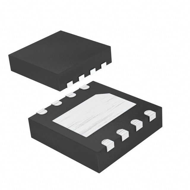
- Part No.:
- MAX17048G+
- Manufacturer:
- Analog Devices Inc./Maxim Integrated
- Category:
- Battery Management
- Package:
- 8-WFDFN Exposed Pad
- Datasheet:
-
 MAX17048G+.pdf
- Description:
- IC BATT MON LI-ION 1CELL 8TDFN
- Quantity:
- Payment:

- Shipping:

Inventory:1,742
Please send an inquiry. Send us your inquiry, and we will respond immediately.
Product details
Overview
The MAX17048G+ from Maxim Integrated is a 1-cell lithium-ion fuel gauge IC that delivers ±7.5mV/cell voltage measurement accuracy, implements the ModelGauge™ algorithm for drift-free state-of-charge (SOC) estimation, and operates with only 3µA quiescent current in hibernate mode - enabling accurate battery monitoring in space-constrained portable devices such as smartwatches and Bluetooth headsets.
For engineers reviewing the MAX17048G+ datasheet, MAX17048G+ pinout, MAX17048G+ application, or MAX17048G+ equivalent, this page provides verified technical context, I²C register-level interface behavior, hibernate/active mode transition thresholds, battery-insertion debounce timing (17ms OCV acquisition), and real-world SOC accuracy validation under dynamic load profiles - all critical for embedded power management design.
Technical Context
The MAX17048G+ uses a physics-based battery model to compute SOC from voltage alone - eliminating coulomb counting error accumulation and removing the need for current-sense resistors or battery learning cycles. Its ModelGauge algorithm adapts to impedance shifts and chemical aging by modeling nonlinear Li+ cell dynamics using internal ROM parameters and optional custom tables.
Temperature compensation requires host µC intervention: RCOMP must be updated at least once per minute using TempCoUp/TempCoDown coefficients. Hibernate mode triggers automatically when |CRATE| < HibThr (configurable down to 0.208%/hr) for >6 minutes, reducing ADC sampling to once per 45s while maintaining SOC accuracy.
Key Specifications
| Parameter | Value and Actual Design Meaning |
|---|---|
| Cell Configuration | 1-cell Li+ only - not compatible with 2-cell stacks; CELL pin connects directly to battery positive terminal. |
| Voltage Accuracy | ±7.5mV/cell at 3.6V and +25°C - enables reliable low-SOC detection without calibration drift. |
| Quiescent Current | 3µA in hibernate mode - extends system standby time without sacrificing fuel-gauge continuity. |
| I²C Interface | Standard-mode (400kHz) with internal pulldowns on SDA/SCL - supports bus disconnection detection and noise filtering (50ns spike suppression). |
| ADC Resolution | 1.25mV/cell - sufficient to resolve 1% SOC steps across full 2.5–4.5V operating range. |
| Debounce Timing | 17ms OCV acquisition window after battery insertion - uses max of 16 × 1ms samples for initial SOC estimate. |
| Hibernate Entry | Auto-enter when |CRATE| < HibThr for >6 minutes - threshold configurable in 0.208%/hr steps via HIBRT register. |
Pinout & Package
MAX17048G+ is packaged in an 0.9mm × 1.7mm, 8-bump wafer-level package (WLP) with bottom-side solder bumps. Pin functions are electrically validated per Maxim's official pin description table and match TDFN pinout mapping for functional equivalence.
| Pin/Terminal | Circuit Role | Design Meaning |
|---|---|---|
| CTG | Chip Ground | Direct connection to negative battery terminal - serves as reference for internal ADC and bias circuits. |
| CELL | Battery Voltage Sense Input | Connects to positive battery terminal; input range 2.5V–5.0V - no internal connection in MAX17049 variant. |
| VDD | Power Supply Input | Supplies internal circuitry; bypass with 0.1µF capacitor - also serves as voltage sense node in MAX17048 configuration. |
| GND | System Ground Reference | Common return path for all analog/digital blocks - must be low-impedance to minimize measurement error. |
| ALRT | Open-Drain Alert Output | Active-low interrupt signal - asserts when SOC drops below ATHD, VCELL exceeds VALRT bounds, or reset occurs. |
| QSTRT | Hardware Quick-Start Trigger | Rising edge forces OCV reacquisition - used only if initial insertion waveform violates 17ms relaxation requirement. |
| SCL | I²C Clock Input | Includes internal pulldown (0.2–0.4µA) - detects bus disconnection and enables automatic sleep entry after 2.5s low condition. |
| SDA | I²C Data I/O | Open-drain bidirectional line with same pulldown as SCL - supports standard-mode timing with 100ns setup/hold margins. |
Key Features
| Feature | Design Value |
|---|---|
| ModelGauge Algorithm | Eliminates coulomb counter drift by computing SOC from voltage-only modeling - no periodic recalibration or full-cycle learning required. |
| Battery-Insertion Debounce | Acquires best-of-16 VCELL samples over 17ms to generate initial SOC estimate - reduces startup error from unrelaxed battery states. |
| Programmable Reset Threshold | VRESET configurable from 2.28V to 3.48V in 40mV steps - enables robust battery swap detection for removable packs. |
| Configurable Alert System | Five independent alerts (low SOC, 1% SOC change, over/under-voltage, VRESET) - each individually maskable via CONFIG register bits. |
| Automatic Hibernate Control | Enters/exits hibernate based on CRATE magnitude and duration - maintains <5µA average current without firmware intervention. |
Applications
| Smart Wearables | Bluetooth Audio Devices |
|---|---|
Use Scenario: Continuous heart-rate monitoring and motion tracking in compact wrist-worn form factors with tight thermal and space constraints. IC Role / Device Role / Timing Role: Primary fuel gauge providing real-time SOC, voltage, and charge/discharge rate via I²C to application MCU. Use Value: 3µA hibernate current extends multi-day battery life; ModelGauge eliminates need for battery-specific learning cycles during production calibration. |
Use Scenario: Wireless earbuds requiring precise low-SOC warning before audio cutoff and seamless battery swap indication. IC Role / Device Role / Timing Role: Standalone fuel gauge interfacing with Bluetooth SoC to trigger UI alerts and manage charging handoff. Use Value: Programmable VRESET (2.28–3.48V) enables reliable detection of battery removal/reinsertion; ALRT pin drives MCU interrupt for immediate state update. |
| Medical Sensors | Digital Cameras |
Use Scenario: Portable ECG or glucose monitors needing FDA-compliant battery runtime prediction and fail-safe shutdown at defined SOC thresholds. IC Role / Device Role / Timing Role: Safety-critical SOC estimator feeding watchdog logic and low-power mode controller. Use Value: ±7.5mV/cell voltage accuracy ensures consistent 3–5% shutdown margin across temperature and aging; no accumulated error over weeks of operation. |
Use Scenario: Action cameras enduring rapid charge/discharge cycles, wide ambient temperature swings (-20°C to +70°C), and mechanical shock. IC Role / Device Role / Timing Role: High-fidelity fuel gauge reporting dynamic CRATE and SOC changes to image processor for power-aware recording control. Use Value: 45s hibernate sampling interval preserves accuracy during idle periods; ModelGauge converges on true SOC within minutes after load transients. |
Equivalent & Alternatives
The following parts are listed as comparable options for similar fuel gauge applications.
| Alternative Part | Technical Difference | Application Difference | Selection Advice |
|---|---|---|---|
| BQ27426YZFT | TI fuel gauge with integrated temperature sensor; requires external current-sense resistor; 4.5µA hibernate current. | Supports coulomb counting + voltage hybrid mode; better suited for systems with precise current monitoring needs. | Select BQ27426YZFT only if host µC lacks temperature sensing capability or if current profiling is required for diagnostics. |
| MAX17050G+T | Same ModelGauge core but supports 1–2 cells; larger 2mm × 2mm TDFN package; 4.5µA hibernate current. | Pin-compatible with MAX17048G+ in WLP footprint but not drop-in due to different bump layout and CELL/VDD assignment. | Choose MAX17050G+T only when dual-cell support or board-level compatibility with existing TDFN layouts is mandatory. |
Compared with BQ27426YZFT and MAX17050G+T, the MAX17048G+ offers the smallest footprint (0.9mm × 1.7mm WLP), lowest hibernate current (3µA), and strictest single-cell optimization - making it optimal for ultra-compact, long-idle wearable designs where coulomb counting adds cost and complexity.
Availability
MAX17048G+ is available at Aetrix Electronics and suitable for smart wearables, Bluetooth audio devices, medical sensors, and digital cameras requiring stable component supply, long-term lifecycle support, and guaranteed traceable sourcing.
Supply support for MAX17048G+ includes scheduled delivery planning, volume procurement assistance, BOM continuity management, traceable sourcing, and lifecycle availability coordination for OEM customers, industrial embedded developers, connected-device designers, and electronics production programs.
Manufacturer
Maxim Integrated (now part of Analog Devices) designs precision analog and mixed-signal ICs for power management, sensing, and connectivity in resource-constrained systems.
The MAX17048G+ belongs to Maxim's ModelGauge fuel gauge product line, engineered specifically for ultra-low-power, single-cell Li+ battery monitoring in size- and energy-sensitive portable electronics.
FAQ
What is the primary function of the MAX17048G+ in a battery-powered system?
The MAX17048G+ serves as a standalone fuel gauge IC that continuously estimates the state-of-charge (SOC), voltage, and charge/discharge rate of a single lithium-ion cell using the ModelGauge algorithm. It communicates results over I²C and requires no external current-sense resistor. The MAX17048G+ replaces traditional coulomb counters by modeling battery chemistry directly from voltage measurements - delivering drift-free SOC accuracy even after weeks of operation without recalibration.
How does the MAX17048G+ achieve ±7.5mV/cell voltage accuracy?
The MAX17048G+ achieves ±7.5mV/cell voltage accuracy through factory-trimmed 12-bit ADC architecture with 1.25mV/cell resolution, calibrated across temperature and supply voltage ranges. This specification is measured at 3.6V and +25°C with 16-sample averaging, and remains within ±20mV/cell over the full -40°C to +85°C operating range. The MAX17048G+ does not require user calibration to meet this spec - it is guaranteed by design and 100% tested at +25°C.
Can the MAX17048G+ be used with two-series lithium cells?
No, the MAX17048G+ is strictly a 1-cell fuel gauge and cannot monitor two-series lithium cells. Its CELL pin is designed for direct connection to a single Li+ cell (2.5V–4.5V range), and its internal ModelGauge parameters are optimized exclusively for single-cell voltage profiles. For 2-cell applications, the pin-compatible MAX17049 variant must be used - the MAX17048G+ lacks the necessary voltage range, internal scaling, and protection thresholds for series-stack configurations.
What triggers automatic hibernate mode entry in the MAX17048G+?
Automatic hibernate mode entry in the MAX17048G+ occurs when the absolute value of the calculated charge/discharge rate (CRATE) remains below the HibThr threshold - set via the HIBRT register - for longer than 6 consecutive minutes. By default, HibThr is configured to 0.208%/hr, meaning sustained near-zero current draw (e.g., RTC backup, sensor polling) will trigger hibernate. Once entered, the MAX17048G+ reduces ADC sampling to once per 45 seconds and lowers quiescent current to 3µA while preserving SOC accuracy.
Is the MAX17048G+ pin-compatible with the MAX17050G+T?
No, the MAX17048G+ is not pin-compatible with the MAX17050G+T despite sharing functional similarity. The MAX17048G+ uses an 0.9mm × 1.7mm 8-bump WLP with bump assignments differing from the 2mm × 2mm 8-pin TDFN layout of the MAX17050G+T. Specifically, CELL and VDD pin roles are swapped between variants, and the WLP bump map does not align mechanically or electrically with TDFN pad positions. Board redesign is required to substitute one for the other.
MAX17048G+ Specifications
- Product attributes
- Attribute value
- Manufacturer:
- Analog Devices Inc./Maxim Integrated
- Series:
- ModelGauge™
- Package/Case:
- 8-WFDFN Exposed Pad
- Packaging:
- Strip
- Product Status:
- Active
- Function:
- Battery Monitor
- Battery Chemistry:
- Lithium Ion
- Number of Cells:
- 1
- Fault Protection:
- -
- Interface:
- I2C
- Operating Temperature:
- -20°C ~ 70°C (TA)
- Grade:
- -
- Qualification:
- -
- Mounting Type:
- Surface Mount
- Supplier Device Package:
- 8-TDFN-EP (2x2)
MAX17048G+ FAQ
1.How can I place an order for MAX17048G+ through Aetrix?
Please submit a Request for Quotation (RFQ) for MAX17048G+ on Aetrix. Our sales agent will provide a competitive quotation and guide you through the order confirmation once you accept the terms.
2.Are the price and stock information for MAX17048G+ reliable?
The price and inventory of MAX17048G+ are updated periodically and may fluctuate due to market conditions. Stock and pricing data are typically refreshed every 24 hours. Quotation validity for MAX17048G+ is usually 5 days.
3.What payment methods are accepted for MAX17048G+?
We accept Wire Transfer, PayPal, Credit Card, Western Union, MoneyGram, and Escrow for MAX17048G+ transactions.
Note: Certain payment methods may incur a processing fee.
4.How is shipping managed for MAX17048G+?
MAX17048G+ orders can be shipped via leading logistics carriers, including DHL, UPS, FedEx, TNT, or Registered Mail.
Once your MAX17048G+ order is processed, you will receive an email with the shipment details and tracking number.
Note: Tracking information may take up to 24 hours to appear. Express delivery typically takes 3–5 business days.
5.How can I obtain technical support or documentation for MAX17048G+?
For technical support, including MAX17048G+ datasheets, pinout diagrams, or application guidance, please contact our engineering support team. They can provide detailed documentation and assistance for your MAX17048G+ requirements.
6.How does Aetrix verify that MAX17048G+ is sourced from the original manufacturer or authorized distributors?
All MAX17048G+ products on Aetrix are procured from qualified distributors and authorized channels. Our dedicated quality assurance team conducts strict verification, including traceability checks and, if necessary, third-party testing. This ensures that MAX17048G+ meets industry standards.
7.What is the process for return or replacement of MAX17048G+?
All MAX17048G+ units undergo pre-shipment inspection (PSI). If there is an issue with MAX17048G+, returns or replacements are accepted under the following conditions:
1.Quantity discrepancies, incorrect items, or visible external defects (such as breakage or corrosion), acknowledged by Aetrix.
2.The issue is reported within 90 days of delivery.
3.The MAX17048G+ part is unused and in its original packaging.
Return procedure for MAX17048G+:
1.Submit a request within 90 days.
2.Obtain a Return Material Authorization (RMA) from Aetrix.
MAX17048G+ Tags

-
BQ29700DSER
Texas Instruments

-
S-8241ABKMC-GBKT2G
ABLIC Inc.
-
S-8241ABPMC-GBPT2G
ABLIC Inc.

-
BQ27427YZFR
Texas Instruments

-
BQ27426YZFR
Texas Instruments

-
STC3117IJT
STMicroelectronics

-
STC3115IJT
STMicroelectronics

-
BQ76925RGER
Texas Instruments
-
NPM1100-QDAA-R
Nordic Semiconductor ASA

-
BQ27441DRZR-G1A
Texas Instruments

-
STC3115AIQT
STMicroelectronics

-
S-8252AAL-M6T1U
ABLIC Inc.
Tech Hub

A practical engineering guide to 3.3V and 5V logic compatibility, input thresholds, resistor dividers, translator ICs, MOSFET level shifting, I2C pull-ups, timing limits and power-sequencing risks.

The 74HC595 uses push-pull logic outputs, while the TPIC6B595 uses 50 V open-drain DMOS sinks for higher-power loads. This guide compares timing, current limits, 3.3 V interfacing, load wiring, thermal…

The 74HC595 converts serial data into eight stable parallel outputs. This guide covers pin functions, shift and storage timing, OE and MR behavior, drive-current limits, cascading, voltage compatibilit…

A technical comparison of level-sensitive latches and edge-triggered flip-flops, covering timing windows, setup and hold limits, master–slave operation, time borrowing, race-through, HDL inference and…

A D latch stores one bit while Enable controls when data can pass. This reference covers gate-level operation, truth tables, transparency, setup and hold timing, LE versus OE, common ICs and practical …

An SR latch stores one bit through cross-coupled feedback. This engineering reference covers NOR and NAND implementations, truth tables, forbidden-state recovery, gated operation, switch debouncing, fa…

Latch circuits retain one bit through feedback. This technical reference covers SR and D latches, truth tables, transparency, timing limits, latch-versus-flip-flop behavior, applications and common log…

An engineering guide to LED driver operation, constant-current and constant-voltage outputs, linear and switching topologies, dimming, IC selection, calculations, replacement compatibility, and fault c…

Operational amplifier guide covering op amp basics, feedback, ideal vs real op amps, common configurations, buffer circuits, offset, bias current, gain-bandwidth, slew rate, rail-to-rail limits and sel…

Jumper cables guide covering safe connection order, red and black clamp placement, final ground connection, cable gauge, length, clamp quality, copper vs CCA cables, jump starter comparison and battery…


