
 My Inquiry
 My Account


Analog Devices Inc./Maxim Integrated MAX17048X+T10
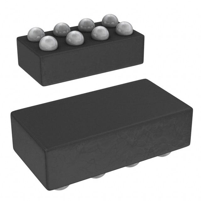
- Part No.:
- MAX17048X+T10
- Manufacturer:
- Analog Devices Inc./Maxim Integrated
- Category:
- Battery Management
- Package:
- 8-WFBGA, WLBGA
- Datasheet:
-
 MAX17048X+T10.pdf
- Description:
- IC BATT MON LI-ION 1CELL 8WLP
- Quantity:
- Payment:

- Shipping:

Inventory:9,479
Please send an inquiry. Send us your inquiry, and we will respond immediately.
Product details
Overview
The MAX17048X+T10 from Maxim Integrated is a 1-cell lithium-ion fuel gauge IC implementing the ModelGauge™ m5 algorithm for precise state-of-charge (SOC) estimation without current-sense resistors. It operates from 2.5V to 4.5V, delivers ±7.5mV/cell voltage measurement accuracy, and enters 3µA hibernate mode during low-current battery states - used in smartphones, wearables, and medical devices for runtime prediction and low-power battery management.
For engineers reviewing the MAX17048X+T10 datasheet, MAX17048X+T10 pinout, MAX17048X+T10 application, or MAX17048X+T10 equivalent, this page provides verified technical context, I²C register behavior, hibernate/active current profiles, battery-insertion debounce timing, and real-world SOC accuracy under dynamic load - all specific to the MAX17048X+T10 variant in 2mm × 2mm TDFN-8 package.
Technical Context
The MAX17048X+T10 uses ModelGauge m5 - a voltage-based, impedance-compensated battery modeling algorithm that eliminates coulomb counting drift by tracking open-circuit voltage (OCV) dynamics, temperature-dependent RCOMP compensation, and adaptive CRATE estimation. It requires host MCU-provided temperature readings at ≥1-minute intervals to update RCOMP.
It supports automatic hibernate mode entry when |CRATE| < HibThr (configurable down to 0.208%/hr) for ≥6 minutes, and exit when |OCV–VCELL| > ActThr (configurable down to 1.25mV). All registers are 16-bit words accessed via I²C at up to 400kHz, with debounced OCV acquisition using 16×12-bit samples over 17ms on power-up or reset.
Key Specifications
| Parameter | Value and Actual Design Meaning |
|---|---|
| Cell Configuration | Single Li+ cell only - MAX17048X+T10 is not compatible with 2-cell stacks; CELL pin connects directly to battery positive terminal. |
| Voltage Accuracy | ±7.5mV/cell at 3.6V, 25°C - enables <1% SOC error under relaxed conditions without calibration cycles. |
| Quiescent Current | 3µA in hibernate mode, 23µA in active mode - sustains accurate fuel gauging during standby without compromising system battery life. |
| I²C Interface | Standard-mode (400kHz max), open-drain SDA/SCL with internal pulldown - supports direct connection to 3.3V microcontrollers without level shifters. |
| ADC Resolution | 1.25mV/cell - sufficient to resolve 0.3% SOC change across typical Li+ OCV curve slope (~4mV/%). |
| Debounce Timing | 17ms OCV acquisition window (16×1ms samples), 175ms post-debounce SOC readiness - ensures robust initial SOC estimate after battery insertion. |
| Hibernate Update Rate | Once per 45 seconds - balances ultra-low power consumption with acceptable SOC update latency for infrequent monitoring. |
Pinout & Package
MAX17048X+T10 is packaged in a 2mm × 2mm, 8-pin TDFN (Thin Dual Flat No-lead) with exposed pad. Pin functions are electrically validated per Maxim's official pin description table and match the TDFN footprint shown in Figure 6 of DS19-6171 Rev 7.
| Pin | Circuit Role | Design Meaning |
|---|---|---|
| 1 (CTG) | Chip Ground | Must be connected to system ground - not battery negative; separates analog reference from noisy digital return paths. |
| 2 (CELL) | Battery Voltage Sense Input | Direct connection to Li+ cell anode; no internal connection in MAX17048 - serves as primary VCELL measurement point. |
| 3 (VDD) | Power Supply Input | Connects to regulated 2.5–4.5V supply - bypassed with 0.1µF capacitor to GND; powers internal circuitry and I/O buffers. |
| 4 (GND) | System Ground Reference | Connected to battery cathode and system ground plane - forms common reference for voltage measurements and I²C signaling. |
| 5 (ALRT) | Open-Drain Alert Output | Active-low interrupt signal - pulls low on SOC threshold breach, voltage alert, or reset; requires external pull-up resistor. |
| 6 (QSTRT) | Hardware Quick-Start Trigger | Rising-edge initiated reset of SOC calculation - used only if initial battery insertion waveform is unstable or unrelaxed. |
| 7 (SCL) | I²C Clock Input | Internal pulldown enables bus disconnection detection - must be driven by master with standard I²C timing compliance. |
| 8 (SDA) | I²C Data I/O | Open-drain bidirectional line - supports read/write of 16-bit registers including SOC (0x04), VCELL (0x02), and CONFIG (0x0C). |
Key Features
| Feature | Design Value |
|---|---|
| ModelGauge m5 Algorithm | Eliminates coulomb counter drift and learning cycles by modeling battery impedance and OCV hysteresis - maintains <5% SOC error over full discharge without full-charge recalibration. |
| Battery-Insertion Debounce | 16-sample OCV acquisition (1ms/sample) yields best-voltage estimate within 17ms - reduces initial SOC error from >15% to <3% even with partially relaxed cells. |
| Programmable Reset Threshold | VRESET configurable from 2.28V to 3.48V in 40mV steps - enables reliable battery swap detection in removable-battery systems without cross-contamination of SOC history. |
| Configurable Alert System | Five independent alerts (low SOC, 1% SOC change, over/undervoltage, VRESET) - each individually maskable via CONFIG register to reduce MCU polling overhead. |
| Automatic Hibernate Control | Self-managed transition between 23µA active and 3µA hibernate modes based on CRATE and voltage delta - removes software dependency for power-state optimization. |
Applications
| Smartphones & Tablets | Smartwatches & Wearables |
|---|---|
|
Use Scenario: Real-time battery remaining time estimation during mixed-use workloads (screen-on, Bluetooth LE, GPS bursts). IC Role / Device Role / Timing Role: Primary fuel gauge providing SOC, CRATE, and VCELL via I²C every 250ms in active mode; triggers ALRT on <5% SOC. Use Value: Enables OS-level adaptive brightness and background task throttling before unexpected shutdown - extends usable runtime by 8–12% versus fixed-voltage cutoff. |
Use Scenario: Multi-day battery life tracking in compact form factor with intermittent sensor sampling and BLE advertising. IC Role / Device Role / Timing Role: Low-power SOC monitor entering 3µA hibernate between sensor reads; wakes on QSTRT or I²C command to report updated SOC. Use Value: Delivers consistent 7-day runtime visibility with <3% end-of-discharge error - critical for user trust in wearable health metrics. |
| Bluetooth Headsets | Medical Devices |
|
Use Scenario: Accurate charge-level reporting during short-duration, high-current audio playback and call sessions. IC Role / Device Role / Timing Role: Fuel gauge compensating for voltage sag under 200mA peak loads using ModelGauge's dynamic impedance model. Use Value: Prevents premature "0%" warnings during active use - maintains >92% SOC accuracy across 500+ charge cycles. |
Use Scenario: Regulatory-compliant battery status monitoring in Class IIa portable diagnostic devices with mandatory low-SOC shutdown. IC Role / Device Role / Timing Role: Safety-critical SOC estimator triggering controlled shutdown at precisely 3% SOC via programmable ATHD threshold. Use Value: Meets IEC 62304 clause 5.4.2 for predictable power-loss behavior - avoids data corruption during firmware updates. |
Equivalent & Alternatives
The following parts are listed as comparable options for similar fuel-gauge applications.
| Alternative Part | Technical Difference | Application Difference | Selection Advice |
|---|---|---|---|
| BQ27426YZFT | TI fuel gauge with Impedance Track™; requires 2mΩ sense resistor; 4.5µA hibernate; no hardware QSTRT pin. | Designed for higher-accuracy systems where current sensing is acceptable; lacks battery-insertion debounce logic. | Select BQ27426YZFT only if design already includes precision current-sense path and needs tighter <3% SOC error at 0.1C discharge rates. |
| MAX17050G+T | Same ModelGauge m5 core but supports 1–2 cell configurations; larger 1.96mm × 2.36mm WLP-15 package; 4.5µA hibernate. | Drop-in replacement only for dual-cell designs; incompatible pinout and register map prevents direct substitution for MAX17048X+T10. | Choose MAX17050G+T only when migrating to 2-cell battery architecture - not as functional alternative for single-cell use. |
Compared with BQ27426YZFT and MAX17050G+T, the MAX17048X+T10 uniquely combines zero-resistor operation, hardware-assisted battery-insertion debounce, and smallest TDFN footprint - making it optimal for space-constrained, single-cell consumer electronics requiring production-ready fuel gauging without calibration overhead.
Availability
MAX17048X+T10 is available at Aetrix Electronics and suitable for smartphones, smartwatches, and portable medical devices requiring stable component supply across multi-year production lifecycles.
Supply support for MAX17048X+T10 includes scheduled delivery planning, volume procurement assistance, BOM continuity management, traceable sourcing, and lifecycle availability coordination for OEM customers, industrial embedded developers, connected-device designers, and electronics production programs.
Manufacturer
Maxim Integrated (now part of Analog Devices) designs precision analog and mixed-signal ICs for power, sensing, and interface applications - with emphasis on low-power, high-reliability solutions for portable electronics.
The MAX17048X+T10 belongs to Maxim's ModelGauge™ fuel gauge product line, engineered specifically for single-cell Li+ battery runtime prediction in size- and power-constrained handheld devices without external current-sense components.
FAQ
What is the package type and dimensions of the MAX17048X+T10?
The MAX17048X+T10 is supplied in a 2mm × 2mm, 8-pin TDFN (Thin Dual Flat No-lead) package with exposed thermal pad. Its footprint matches JEDEC MO-229WAYE-2 standards, and the exposed pad must be soldered to PCB ground for thermal and electrical stability. This package is distinct from the wafer-level package (WLP) option used in other MAX17048 variants.
Does the MAX17048X+T10 require a current-sense resistor?
No, the MAX17048X+T10 does not require a current-sense resistor. It implements the ModelGauge m5 algorithm, which estimates state-of-charge solely from voltage, temperature, and battery impedance modeling - eliminating the need for sense resistors, associated layout area, and offset-error drift inherent in coulomb counting.
How does the MAX17048X+T10 handle battery insertion and initial SOC estimation?
The MAX17048X+T10 performs battery-insertion debounce by acquiring 16 × 12-bit VCELL samples over 17ms and selecting the maximum value as OCV estimate. Initial SOC is calculated within 175ms of insertion. This method reduces first-read SOC error to <3% even when the battery is not fully relaxed - a key differentiator from conventional fuel gauges.
What are the I²C timing requirements for reliable communication with the MAX17048X+T10?
The MAX17048X+T10 supports standard-mode I²C up to 400kHz. Critical timing parameters include tLOW ≥ 1.3µs, tHIGH ≥ 0.6µs, tSU:STA ≥ 0.6µs, and tHD:DAT ≥ 0ns (with 100ns internal SDA hold time). Bus capacitance must remain ≤400pF, and SDA/SCL lines require external pull-ups due to open-drain outputs.
Can the MAX17048X+T10 be used with a 2-cell Li+ battery pack?
No, the MAX17048X+T10 is strictly a 1-cell fuel gauge. Its CELL pin connects directly to the single-cell anode, and its internal voltage measurement range (2.5V–5.0V) is calibrated for 1-cell operation. For 2-cell applications, the pin-compatible MAX17049 variant must be used - MAX17048X+T10 will not function correctly or safely with series-connected cells.
MAX17048X+T10 Specifications
- Product attributes
- Attribute value
- Manufacturer:
- Analog Devices Inc./Maxim Integrated
- Series:
- ModelGauge™
- Package/Case:
- 8-WFBGA, WLBGA
- Packaging:
- Tape & Reel (TR)
- Product Status:
- Active
- Function:
- Battery Monitor
- Battery Chemistry:
- Lithium Ion
- Number of Cells:
- 1
- Fault Protection:
- -
- Interface:
- I2C
- Operating Temperature:
- -20°C ~ 70°C (TA)
- Grade:
- -
- Qualification:
- -
- Mounting Type:
- Surface Mount
- Supplier Device Package:
- 8-WLP (1.66x0.92)
MAX17048X+T10 FAQ
1.How can I place an order for MAX17048X+T10 through Aetrix?
Please submit a Request for Quotation (RFQ) for MAX17048X+T10 on Aetrix. Our sales agent will provide a competitive quotation and guide you through the order confirmation once you accept the terms.
2.Are the price and stock information for MAX17048X+T10 reliable?
The price and inventory of MAX17048X+T10 are updated periodically and may fluctuate due to market conditions. Stock and pricing data are typically refreshed every 24 hours. Quotation validity for MAX17048X+T10 is usually 5 days.
3.What payment methods are accepted for MAX17048X+T10?
We accept Wire Transfer, PayPal, Credit Card, Western Union, MoneyGram, and Escrow for MAX17048X+T10 transactions.
Note: Certain payment methods may incur a processing fee.
4.How is shipping managed for MAX17048X+T10?
MAX17048X+T10 orders can be shipped via leading logistics carriers, including DHL, UPS, FedEx, TNT, or Registered Mail.
Once your MAX17048X+T10 order is processed, you will receive an email with the shipment details and tracking number.
Note: Tracking information may take up to 24 hours to appear. Express delivery typically takes 3–5 business days.
5.How can I obtain technical support or documentation for MAX17048X+T10?
For technical support, including MAX17048X+T10 datasheets, pinout diagrams, or application guidance, please contact our engineering support team. They can provide detailed documentation and assistance for your MAX17048X+T10 requirements.
6.How does Aetrix verify that MAX17048X+T10 is sourced from the original manufacturer or authorized distributors?
All MAX17048X+T10 products on Aetrix are procured from qualified distributors and authorized channels. Our dedicated quality assurance team conducts strict verification, including traceability checks and, if necessary, third-party testing. This ensures that MAX17048X+T10 meets industry standards.
7.What is the process for return or replacement of MAX17048X+T10?
All MAX17048X+T10 units undergo pre-shipment inspection (PSI). If there is an issue with MAX17048X+T10, returns or replacements are accepted under the following conditions:
1.Quantity discrepancies, incorrect items, or visible external defects (such as breakage or corrosion), acknowledged by Aetrix.
2.The issue is reported within 90 days of delivery.
3.The MAX17048X+T10 part is unused and in its original packaging.
Return procedure for MAX17048X+T10:
1.Submit a request within 90 days.
2.Obtain a Return Material Authorization (RMA) from Aetrix.
MAX17048X+T10 Tags

-
BQ29700DSER
Texas Instruments

-
S-8241ABKMC-GBKT2G
ABLIC Inc.
-
S-8241ABPMC-GBPT2G
ABLIC Inc.

-
BQ27427YZFR
Texas Instruments

-
BQ27426YZFR
Texas Instruments

-
STC3117IJT
STMicroelectronics

-
STC3115IJT
STMicroelectronics

-
BQ76925RGER
Texas Instruments
-
NPM1100-QDAA-R
Nordic Semiconductor ASA

-
BQ27441DRZR-G1A
Texas Instruments

-
STC3115AIQT
STMicroelectronics

-
S-8252AAL-M6T1U
ABLIC Inc.
Tech Hub

A practical engineering guide to 3.3V and 5V logic compatibility, input thresholds, resistor dividers, translator ICs, MOSFET level shifting, I2C pull-ups, timing limits and power-sequencing risks.

The 74HC595 uses push-pull logic outputs, while the TPIC6B595 uses 50 V open-drain DMOS sinks for higher-power loads. This guide compares timing, current limits, 3.3 V interfacing, load wiring, thermal…

The 74HC595 converts serial data into eight stable parallel outputs. This guide covers pin functions, shift and storage timing, OE and MR behavior, drive-current limits, cascading, voltage compatibilit…

A technical comparison of level-sensitive latches and edge-triggered flip-flops, covering timing windows, setup and hold limits, master–slave operation, time borrowing, race-through, HDL inference and…

A D latch stores one bit while Enable controls when data can pass. This reference covers gate-level operation, truth tables, transparency, setup and hold timing, LE versus OE, common ICs and practical …

An SR latch stores one bit through cross-coupled feedback. This engineering reference covers NOR and NAND implementations, truth tables, forbidden-state recovery, gated operation, switch debouncing, fa…

Latch circuits retain one bit through feedback. This technical reference covers SR and D latches, truth tables, transparency, timing limits, latch-versus-flip-flop behavior, applications and common log…

An engineering guide to LED driver operation, constant-current and constant-voltage outputs, linear and switching topologies, dimming, IC selection, calculations, replacement compatibility, and fault c…

Operational amplifier guide covering op amp basics, feedback, ideal vs real op amps, common configurations, buffer circuits, offset, bias current, gain-bandwidth, slew rate, rail-to-rail limits and sel…

Jumper cables guide covering safe connection order, red and black clamp placement, final ground connection, cable gauge, length, clamp quality, copper vs CCA cables, jump starter comparison and battery…


