
 My Inquiry
 My Account


Analog Devices Inc./Maxim Integrated MAX17841BGUE/V+
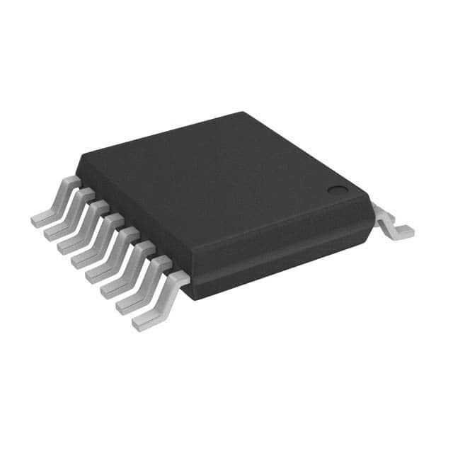
- Part No.:
- MAX17841BGUE/V+
- Manufacturer:
- Analog Devices Inc./Maxim Integrated
- Category:
- Battery Management
- Package:
- 16-TSSOP (0.173", 4.40mm Width)
- Datasheet:
-
 MAX17841BGUE/V+.pdf
- Description:
- IC BATT MFUNC 16TSSOP
- Quantity:
- Payment:

- Shipping:

Inventory:1,866
Please send an inquiry. Send us your inquiry, and we will respond immediately.
Product details
Overview
MAX17841BGUE/V+ from Maxim Integrated is an Automotive SPI Communication Interface (ASCI) IC that bridges host microcontrollers to Maxim battery management slave devices via a dedicated UART protocol. It integrates a 4MHz SPI slave port, programmable 0.5/1/2Mbps UART with Manchester encoding/decoding, 28-byte transmit and 62-byte receive buffers, and operates from -40°C to +105°C per AEC-Q100 Type 2 for use in high-reliability BMS daisy-chain topologies.
For engineers reviewing the MAX17841BGUE/V+ datasheet, MAX17841BGUE/V+ pinout, MAX17841BGUE/V+ application, or MAX17841BGUE/V+ equivalent, key selection criteria include its dual-voltage support (3.3V/5V), integrated 3.3V LDO regulator (VAA output), differential UART transceiver (TXP/TXN/RXP/RXN), ultra-low shutdown current (≤10µA), and ASIL-compliant operation in automotive battery management systems.
Technical Context
The MAX17841BGUE/V+ implements a half-duplex SPI interface (mode 0, CPOL=0/CPHA=0) with 4MHz max clock, supporting register access and buffer transactions. Its UART subsystem handles full protocol stack offload-including Manchester encoding/decoding, preamble/stop framing, CRC-8 PEC generation/verification, and keep-alive signaling-enabling host controllers to manage up to 32 daisy-chained battery monitors without real-time timing constraints.
Internally, it features a 16MHz oscillator, 3.3V LDO regulator (VAA output), and independent power domains: DCIN (SPI/LDO input), VAA (oscillator/LDO output), and VDDL/GNDL (UART/digital I/O). Fault detection includes open-circuit monitoring on VDDL, GNDL, and AGND, with ±28V common-mode tolerance on RXP/RXN inputs and 20mA absolute max pin current rating.
Key Specifications
| Parameter | Value and Actual Design Meaning |
|---|---|
| SPI Clock Frequency | Up to 4MHz - enables fast register configuration and buffer loading without CPU overhead. |
| UART Baud Rate | 0.5 / 1 / 2Mbps - selectable for trade-off between noise immunity and data throughput in noisy automotive environments. |
| Operating Temperature | -40°C to +105°C - qualified per AEC-Q100 Type 2 for under-hood and battery-pack placement. |
| Supply Voltage Range | DCIN: 3.1–3.5V (3.3V mode) or 4.5–5.5V (5V mode) - supports dual-rail system integration. |
| Shutdown Current | ≤10µA at VDCIN = 5V - minimizes standby power in always-on BMS monitoring circuits. |
| UART Buffer Size | 28-byte TX / 62-byte RX - accommodates multi-device WRITEALL/READALL messages with PEC and framing. |
| Differential Input Range | RXP/RXN: ±28V common-mode - ensures robust communication across isolated battery cell stacks. |
Pinout & Package
MAX17841BGUE/V+ is housed in a 16-pin TSSOP package (4.4mm × 5mm, 0.65mm pitch) with exposed pad for thermal performance. Pin functions are validated per Maxim's official datasheet Rev 3 (3/21).
| Pin/Terminal | Circuit Role | Design Meaning |
|---|---|---|
| VAA | Power Output / Oscillator Supply | LDO output (3.3V) in 5V mode; external 3.3V supply input in 3.3V mode - powers internal oscillator and analog circuitry. |
| AGND | Analog Ground Reference | Reference for DCIN, SHDN, CS, DIN, SCLK, DOUT, INT - must be connected to system power ground. |
| DCIN | Main Power Input | Input to internal LDO (5V mode) or direct 3.3V supply (3.3V mode) - powers SPI port and regulator. |
| SHDN | Active-Low Shutdown Control | Resets registers, disables LDO, halts UART - internal 1.5MΩ pulldown enables default-active operation. |
| CS | SPI Chip Select | Active-low enable for SPI transactions - internal 12MΩ pulldown prevents spurious activation. |
| DIN | SPI Data Input | Host MOSI connection - 5V-tolerant, accepts MSB-first commands for register/buffer access. |
| DOUT | SPI Data Output | Host MISO connection - three-state when CS high; driven between DCIN and AGND when active. |
| SCLK | SPI Clock Input | Host SCLK connection - 5V-tolerant, sampled on rising edge (CPHA=0) for synchronous transfers. |
| INT | Open-Drain Interrupt Output | Asserts low on UART/SPI event (e.g., RX full, TX complete) - requires external pullup for host GPIO wake-up. |
| TXP/TXN | Differential UART Transmit Outputs | Drive slave device Rx inputs - swing between VDDL and GNDL with 20mA drive strength and ±28V fault tolerance. |
| RXP/RXN | Differential UART Receive Inputs | Accept slave Tx outputs - support ±28V common-mode range and 75mV typical hysteresis for noise rejection. |
| VDDL/GNDL | Digital UART Power/Ground | Isolated domain for UART I/O - decoupled separately to suppress coupling between SPI and battery-stack signals. |
Key Features
| Feature | Design Value |
|---|---|
| Automotive UART Protocol Offload | Hardware-accelerated Manchester encoding/decoding, preamble/stop framing, and CRC-8 PEC handling - eliminates host firmware complexity for BMS daisy-chain messaging. |
| Configurable Keep-Alive Signaling | Programmable idle timeout (0–10.24ms) with periodic stop-character transmission - prevents unintended slave shutdown during host sleep cycles. |
| Dual-Voltage Operation | Supports 3.3V or 5V DCIN with internal LDO - simplifies integration into mixed-voltage automotive ECUs and battery packs. |
| Robust Isolation Interface | ±28V common-mode tolerance on RXP/RXN and fault detection on VDDL/GNDL/AGND - enables reliable communication across galvanically isolated cell monitors. |
| ASIL-Compliant Design | Meets requirements for ASIL-B/C systems per ISO 26262 - validated by AEC-Q100 qualification and built-in diagnostics (POR, open-detection, interrupt flagging). |
Applications
| Battery Pack Cell Monitoring | EV/HEV Battery Management Controller |
|---|---|
|
Use Scenario: Real-time voltage, temperature, and state-of-charge acquisition from 12–96 series-connected lithium-ion cells using daisy-chained MAX17853/MAX17852 monitors. IC Role / Device Role / Timing Role: ASCI acts as SPI-to-UART bridge, translating host commands into Maxim's battery management UART protocol with automatic Manchester encoding and PEC validation. Use Value: Enables deterministic, low-latency communication with <10µs jitter on UART bit timing and guaranteed message integrity across 32-node chains. |
Use Scenario: Central BMS controller in electric vehicle traction battery pack coordinating charge/discharge control, thermal management, and safety cutoffs. IC Role / Device Role / Timing Role: Provides fault-tolerant, ASIL-compliant interface between MCU and distributed cell monitoring ICs - handles wake-up, keep-alive, and error recovery autonomously. Use Value: Reduces host CPU load by >70% versus software UART implementation and supports hot-plug detection via VDDL/GNDL open-circuit monitoring. |
| Energy Storage System (ESS) Rack Controller | Hybrid Electric Vehicle DC-Link Monitor |
|
Use Scenario: Grid-scale ESS rack with 24 parallel battery modules, each containing 16-series cell strings monitored via MAX1785x slaves. IC Role / Device Role / Timing Role: Acts as protocol gateway between industrial PLC (via SPI) and distributed battery monitors - manages address assignment (HELLOALL), broadcast writes (WRITEALL), and synchronized reads (READALL). Use Value: Supports >100ms total round-trip latency for full-stack polling while maintaining <1% packet error rate in EMI-heavy substation environments. |
Use Scenario: HEV power electronics unit monitoring DC-link capacitor health and pre-charge status across multiple battery banks during engine start-stop cycles. IC Role / Device Role / Timing Role: Interfaces MCU to isolated high-side cell monitors on DC-link branch - uses differential UART (TXP/TXN/RXP/RXN) to reject common-mode noise from IGBT switching transients. Use Value: Achieves >60dB CMRR at 10kHz via hardware differential receiver design, eliminating need for external signal conditioning. |
Equivalent & Alternatives
The following parts are listed as comparable options for similar automotive SPI-to-UART bridge applications.
| Alternative Part | Technical Difference | Application Difference | Selection Advice |
|---|---|---|---|
| MAX17841GWE+ | Same functionality and pinout; differs only in temperature grade (industrial -40°C to +85°C vs. automotive -40°C to +105°C) and AEC-Q100 qualification. | Not suitable for under-hood or battery-pack mounting where ambient exceeds +85°C or ASIL compliance is required. | Select MAX17841BGUE/V+ for automotive BMS; MAX17841GWE+ only for non-automotive industrial ESS control units. |
| MAX17853 | Slave-side battery monitor IC (not ASCI); integrates ADC, cell balancing, and watchdog - lacks SPI master interface and UART protocol offload. | Cannot replace MAX17841BGUE/V+ as host-side interface; used downstream in same daisy-chain as slave device. | MAX17841BGUE/V+ and MAX17853 are complementary - not substitutes. Use MAX17841BGUE/V+ to control MAX17853 networks. |
Compared with MAX17841GWE+, the MAX17841BGUE/V+ adds AEC-Q100 qualification, extended temperature operation, and enhanced fault detection for automotive deployment; compared with MAX17853, it serves a fundamentally different role as host-side protocol bridge rather than cell-level monitor.
Availability
MAX17841BGUE/V+ is available at Aetrix Electronics and suitable for battery management systems (BMS), electric/hybrid vehicle (EV/HEV) powertrain controls, and energy storage systems (ESS) requiring stable component supply, long-term lifecycle assurance, and automotive-grade reliability.
Supply support for MAX17841BGUE/V+ includes scheduled delivery planning, volume procurement assistance, BOM continuity management, traceable sourcing, and lifecycle availability coordination for OEM customers, industrial embedded developers, connected-device designers, and electronics production programs.
Manufacturer
Maxim Integrated (now part of Analog Devices) designs precision analog, mixed-signal, and power management ICs for automotive, industrial, and communications markets - emphasizing high reliability, low power, and functional safety.
The MAX17841BGUE/V+ belongs to Maxim's Automotive Battery Management Interface product line, engineered specifically to simplify host-controller integration with daisy-chained battery monitors while meeting ASIL requirements and harsh-environment operating conditions.
FAQ
What is the primary function of the MAX17841BGUE/V+ in a battery management system?
The MAX17841BGUE/V+ serves as an Automotive SPI Communication Interface (ASCI) that bridges a host microcontroller's SPI port to Maxim battery management slave devices (e.g., MAX17853) using a proprietary UART protocol. It handles Manchester encoding/decoding, message framing, CRC-8 PEC calculation, and keep-alive signaling - offloading these tasks from the host CPU and enabling reliable daisy-chain communication across up to 32 nodes. The MAX17841BGUE/V+ is essential for deterministic, low-overhead BMS data acquisition in EV/HEV and ESS applications.
Does the MAX17841BGUE/V+ support both 3.3V and 5V operation, and how is voltage mode selected?
Yes, the MAX17841BGUE/V+ supports dual-voltage operation: in 3.3V mode, DCIN and VAA are externally supplied at 3.3V; in 5V mode, DCIN is supplied at 5V and the internal LDO regulates VAA to 3.3V. Mode selection is hardware-defined by the applied voltages - no configuration register setting is required. The 3.3V LDO delivers up to 10mA and powers the oscillator and analog circuitry, while VDDL must be tied to VAA in both modes per the application circuit.
How does the MAX17841BGUE/V+ ensure robust communication in noisy automotive environments?
The MAX17841BGUE/V+ ensures robustness through differential UART signaling (TXP/TXN and RXP/RXN) with ±28V common-mode input range, 75mV typical hysteresis on differential receivers, and hardware Manchester encoding that provides inherent DC balance and clock recovery. It also includes open-circuit detection on VDDL, GNDL, and AGND, and meets AEC-Q100 Type 2 qualification for -40°C to +105°C operation - all critical for surviving EMI and thermal stress in EV battery packs. These features collectively eliminate the need for external isolation or signal conditioning in most BMS designs.
What UART baud rates does the MAX17841BGUE/V+ support, and how are they configured?
The MAX17841BGUE/V+ supports three fixed UART baud rates: 0.5Mbps, 1Mbps, and 2Mbps. These are selected via the BAUD[1:0] bits in the CONFIG register (address 0x00), with no fractional divider or external clock dependency. The 2Mbps rate enables sub-100µs round-trip latency for single-register READALL/WRITEALL commands across 10-node daisy-chains, while lower rates improve noise immunity in high-EMI zones. All rates maintain strict timing compliance per the Maxim battery management UART protocol specification.
Can the MAX17841BGUE/V+ operate without external crystal or oscillator components?
Yes, the MAX17841BGUE/V+ contains an internal 16MHz oscillator (15.68–16.32MHz, ±2% tolerance) that drives the UART and SPI timing - no external crystal or resonator is required. This oscillator powers the UART bit timing, SPI clock synchronization, and internal logic, reducing BOM count and PCB area. The VAA pin supplies the oscillator circuitry; in 5V mode, VAA is generated internally from DCIN, while in 3.3V mode, VAA must be supplied externally at 3.3V.
MAX17841BGUE/V+ Specifications
- Product attributes
- Attribute value
- Manufacturer:
- Analog Devices Inc./Maxim Integrated
- Series:
- -
- Package/Case:
- 16-TSSOP (0.173", 4.40mm Width)
- Packaging:
- Tube
- Product Status:
- Active
- Function:
- Multi-Function Controller
- Battery Chemistry:
- -
- Number of Cells:
- -
- Fault Protection:
- -
- Interface:
- SPI, UART
- Operating Temperature:
- -40°C ~ 105°C (TA)
- Grade:
- Automotive
- Qualification:
- AEC-Q100
- Mounting Type:
- Surface Mount
- Supplier Device Package:
- 16-TSSOP
MAX17841BGUE/V+ FAQ
1.How can I place an order for MAX17841BGUE/V+ through Aetrix?
Please submit a Request for Quotation (RFQ) for MAX17841BGUE/V+ on Aetrix. Our sales agent will provide a competitive quotation and guide you through the order confirmation once you accept the terms.
2.Are the price and stock information for MAX17841BGUE/V+ reliable?
The price and inventory of MAX17841BGUE/V+ are updated periodically and may fluctuate due to market conditions. Stock and pricing data are typically refreshed every 24 hours. Quotation validity for MAX17841BGUE/V+ is usually 5 days.
3.What payment methods are accepted for MAX17841BGUE/V+?
We accept Wire Transfer, PayPal, Credit Card, Western Union, MoneyGram, and Escrow for MAX17841BGUE/V+ transactions.
Note: Certain payment methods may incur a processing fee.
4.How is shipping managed for MAX17841BGUE/V+?
MAX17841BGUE/V+ orders can be shipped via leading logistics carriers, including DHL, UPS, FedEx, TNT, or Registered Mail.
Once your MAX17841BGUE/V+ order is processed, you will receive an email with the shipment details and tracking number.
Note: Tracking information may take up to 24 hours to appear. Express delivery typically takes 3–5 business days.
5.How can I obtain technical support or documentation for MAX17841BGUE/V+?
For technical support, including MAX17841BGUE/V+ datasheets, pinout diagrams, or application guidance, please contact our engineering support team. They can provide detailed documentation and assistance for your MAX17841BGUE/V+ requirements.
6.How does Aetrix verify that MAX17841BGUE/V+ is sourced from the original manufacturer or authorized distributors?
All MAX17841BGUE/V+ products on Aetrix are procured from qualified distributors and authorized channels. Our dedicated quality assurance team conducts strict verification, including traceability checks and, if necessary, third-party testing. This ensures that MAX17841BGUE/V+ meets industry standards.
7.What is the process for return or replacement of MAX17841BGUE/V+?
All MAX17841BGUE/V+ units undergo pre-shipment inspection (PSI). If there is an issue with MAX17841BGUE/V+, returns or replacements are accepted under the following conditions:
1.Quantity discrepancies, incorrect items, or visible external defects (such as breakage or corrosion), acknowledged by Aetrix.
2.The issue is reported within 90 days of delivery.
3.The MAX17841BGUE/V+ part is unused and in its original packaging.
Return procedure for MAX17841BGUE/V+:
1.Submit a request within 90 days.
2.Obtain a Return Material Authorization (RMA) from Aetrix.
MAX17841BGUE/V+ Tags

-
BQ29700DSER
Texas Instruments

-
S-8241ABKMC-GBKT2G
ABLIC Inc.
-
S-8241ABPMC-GBPT2G
ABLIC Inc.

-
BQ27427YZFR
Texas Instruments

-
BQ27426YZFR
Texas Instruments

-
STC3117IJT
STMicroelectronics

-
STC3115IJT
STMicroelectronics

-
BQ76925RGER
Texas Instruments
-
NPM1100-QDAA-R
Nordic Semiconductor ASA

-
BQ27441DRZR-G1A
Texas Instruments

-
STC3115AIQT
STMicroelectronics

-
S-8252AAL-M6T1U
ABLIC Inc.
Tech Hub

A practical engineering guide to 3.3V and 5V logic compatibility, input thresholds, resistor dividers, translator ICs, MOSFET level shifting, I2C pull-ups, timing limits and power-sequencing risks.

The 74HC595 uses push-pull logic outputs, while the TPIC6B595 uses 50 V open-drain DMOS sinks for higher-power loads. This guide compares timing, current limits, 3.3 V interfacing, load wiring, thermal…

The 74HC595 converts serial data into eight stable parallel outputs. This guide covers pin functions, shift and storage timing, OE and MR behavior, drive-current limits, cascading, voltage compatibilit…

A technical comparison of level-sensitive latches and edge-triggered flip-flops, covering timing windows, setup and hold limits, master–slave operation, time borrowing, race-through, HDL inference and…

A D latch stores one bit while Enable controls when data can pass. This reference covers gate-level operation, truth tables, transparency, setup and hold timing, LE versus OE, common ICs and practical …

An SR latch stores one bit through cross-coupled feedback. This engineering reference covers NOR and NAND implementations, truth tables, forbidden-state recovery, gated operation, switch debouncing, fa…

Latch circuits retain one bit through feedback. This technical reference covers SR and D latches, truth tables, transparency, timing limits, latch-versus-flip-flop behavior, applications and common log…

An engineering guide to LED driver operation, constant-current and constant-voltage outputs, linear and switching topologies, dimming, IC selection, calculations, replacement compatibility, and fault c…

Operational amplifier guide covering op amp basics, feedback, ideal vs real op amps, common configurations, buffer circuits, offset, bias current, gain-bandwidth, slew rate, rail-to-rail limits and sel…

Jumper cables guide covering safe connection order, red and black clamp placement, final ground connection, cable gauge, length, clamp quality, copper vs CCA cables, jump starter comparison and battery…


