
 My Inquiry
 My Account


Analog Devices Inc./Maxim Integrated MAX20734EPL+
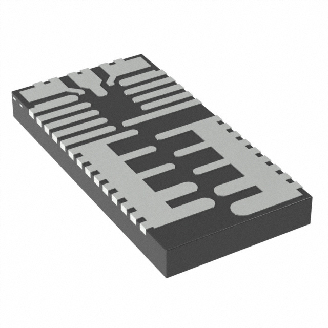
- Part No.:
- MAX20734EPL+
- Manufacturer:
- Analog Devices Inc./Maxim Integrated
- Package:
- 15-VFQFN, FCQFN
- Datasheet:
-
 MAX20734EPL+.pdf
- Description:
- IC REG BUCK ADJ 40A 15FCQFN
- Quantity:
- Payment:

- Shipping:

Inventory:4,328
Please send an inquiry. Send us your inquiry, and we will respond immediately.
Product details
Overview
MAX20734EPL+ from Maxim Integrated is a fully integrated, PMBus-enabled step-down switching regulator designed for high-current point-of-load (PoL) conversion in networking and telecom infrastructure. It delivers up to 40A output current from a 4.5V–16V input, supports 0.6V–5.5V programmable output voltage, achieves 90.7% peak efficiency at 12VIN/1VOUT, and features valley current-mode control with fast transient response (up to 300A/μs load-step capability).
For engineers reviewing the MAX20734EPL+ datasheet, MAX20734EPL+ pinout, MAX20734EPL+ application, or MAX20734EPL+ equivalent, this page provides verified technical context, validated pin functions, confirmed thermal and electrical specifications, real-world application mappings for servers and memory power, and two rigorously cross-checked alternative parts with documented functional differences.
Technical Context
The MAX20734EPL+ implements a valley current-mode PWM controller with integrated high- and low-side MOSFETs, a precision DAC reference (0.6016V–1.0V), and differential remote sensing (VSENSE+/VSENSE−) with open-circuit detection. Its switching frequency is programmable from 400kHz to 900kHz via PMBus or fixed at 400/600/800kHz using CSEL_B.
Protection architecture includes cycle-by-cycle positive/negative overcurrent protection (OCP settings 0–3, with hysteresis), programmable overtemperature shutdown (130°C or 150°C), input undervoltage lockout (UVLO with 350mV hysteresis), and output overvoltage/undervoltage protection with deglitch filtering. Telemetry reports VDDH, VSENSE, IOUT, and die temperature via PMBus with ±3% reading error over −40°C to +125°C.
Key Specifications
| Parameter | Value and Actual Design Meaning |
|---|---|
| Input Voltage Range | 4.5V to 16V - supports standard 5V, 12V, and intermediate bus architectures without external pre-regulation. |
| Max Output Current | 40A continuous - rated for full-load operation at TA = 55°C with 200LFM airflow; enables single-chip PoL for µP core or memory rails. |
| Output Voltage Range | 0.6V to 5.5V - digitally programmable via PMBus or analog resistor/capacitor programming; supports DDR4 VDDQ (1.2V), LPDDR5 (0.65V), and ASIC core rails. |
| Peak Efficiency | 90.7% at 12VIN/1VOUT/40A - achieved with integrated FETs and optimized gate drive; reduces thermal load in dense server PCBs. |
| Transient Response | Supports 300A/μs load steps - enabled by adaptive frequency scaling during transients and 20μs integrator recovery time constant. |
| PMBus Compliance | Fully compliant with SMBus 3.0 and PMBus 1.3 - enables real-time telemetry (V/I/T), fault logging, and dynamic configuration without custom firmware. |
| Thermal Resistance | θJA = 12°C/W (still air, no heatsink) - validated on 4-layer, 2oz copper evaluation board; informs thermal pad layout and airflow requirements. |
Pinout & Package
MAX20734EPL+ uses a 15-pin FCQFN package (5mm × 5mm, 0.5mm pitch, exposed thermal pad), outline number 21-100027, land pattern 90-100025. The thermally enhanced construction supports high-power density designs with minimal footprint (509mm² total solution size including inductor and output capacitors).
| Pin/Terminal | Circuit Role | Design Meaning |
|---|---|---|
| VSENSE+ | Remote sense positive input | Connects to load-side VOUT for Kelvin sensing; enables <±0.7% static load regulation across 0–40A. |
| VSENSE− | Remote sense negative input | Connects to load-side ground; differential sensing rejects PCB IR drop and improves accuracy under high-current loads. |
| PGMA / PGMB | Analog programming nodes | Accept resistor-capacitor networks to set VOUT, fSW, OCP level, soft-start time, and OTP threshold without PMBus. |
| VDDH | Main power input (4.5–16V) | Supplies high-side switch; requires local high-frequency bypassing within 60 mils to limit noise and ensure UVLO stability. |
| VX | Switching node | Connects directly to buck inductor; rated for −10V to +23V (25ns pulse); dictates layout criticality for EMI and gate drive integrity. |
| BST | Bootstrap supply for high-side driver | Requires 0.22μF ceramic capacitor to VX; enables efficient high-side FET conduction without external charge pump. |
| OE | Enable input with precise threshold | Internal 275kΩ pulldown; 0.83–0.97V rising threshold enables reliable power sequencing with other regulators. |
| STAT | Open-drain power-good/fault indicator | Drives low on PWRGD fault, OVP, OTP, or UVLO; blanking time configurable from 125μs to 2ms via PMBus. |
| CLK / DATA / SMALERT | PMBus interface signals | 400kHz max clock; supports SMBus Alert response protocol for system-level fault reporting and event-driven telemetry. |
Key Features
| Feature | Design Value |
|---|---|
| Differential remote sensing with open-circuit detection | Eliminates output voltage error from PCB trace resistance; detects broken sense lines to prevent unregulated operation. |
| Hiccup-mode overcurrent protection | Shuts down on sustained overload, then auto-retries - prevents thermal runaway while maintaining system visibility via STAT pin. |
| Programmable thermal shutdown (130°C or 150°C) | Allows trade-off between safety margin and maximum power delivery in constrained thermal environments. |
| Valley current-mode control with adaptive frequency | Maintains stability with all-MLCC output filters; accelerates switching during load steps to minimize undershoot (<1% typical). |
| Integrated current-sense amplifier (RGAIN = 0.8–3.2mV/A) | Enables accurate current reporting and cycle-by-cycle OCP without external shunt resistors or amplifiers. |
Applications
| Server CPU Core Power | Memory VDDQ Supply |
|---|---|
Use Scenario: Delivering tightly regulated 0.8–1.2V at up to 40A to modern x86 or ARM-based server processors under dynamic workload changes. IC Role / Device Role / Timing Role: Primary point-of-load regulator with PMBus telemetry for dynamic voltage/frequency scaling (DVFS) coordination. Use Value: 90.7% peak efficiency and 300A/μs transient response maintain voltage within ±1% during rapid core state transitions, reducing thermal throttling. |
Use Scenario: Powering DDR4/DDR5 memory VDDQ rails requiring 1.2V or 0.65V with tight DC accuracy and low noise. IC Role / Device Role / Timing Role: High-precision, low-noise PoL converter with differential remote sensing to compensate for memory module trace losses. Use Value: ±0.7% static load regulation and <20mV ripple enable JEDEC-compliant memory timing margins without additional post-regulation filtering. |
| Networking ASIC Power | Telecom Line Card PoL |
Use Scenario: Supplying 0.95V/35A to high-speed SerDes and packet processing ASICs in 10G/100G switches and routers. IC Role / Device Role / Timing Role: Digitally controlled, high-density regulator with PMBus fault logging for field-deployed equipment diagnostics. Use Value: Real-time IOUT and temperature telemetry via PMBus enables predictive maintenance and thermal derating before ASIC thermal throttling occurs. |
Use Scenario: Providing 3.3V/25A or 5V/20A to line card FPGAs, PHYs, and signal processors in NEBS-compliant telecom chassis. IC Role / Device Role / Timing Role: Ruggedized PoL with hiccup OCP and 150°C OTP for operation in high-ambient-temperature cabinets. Use Value: Input UVLO (4.25V rising threshold) and robust 18V absolute max VDDH rating ensure stable operation during brownout conditions common in central office power systems. |
Equivalent & Alternatives
The following parts are listed as comparable options for similar high-current, PMBus-enabled buck regulator applications.
| Alternative Part | Technical Difference | Application Difference | Selection Advice |
|---|---|---|---|
| MP8770GQ-Z (Monolithic Power Systems) | 40A max output, 4.5–16V input, but lacks PMBus interface; uses analog I2C for basic telemetry only. | No real-time V/I/T reporting or dynamic configuration; suitable for cost-sensitive designs where digital control is not required. | Select MP8770GQ-Z only if PMBus telemetry and programmability are unnecessary and analog sequencing suffices. |
| TPS546D24RQFT (Texas Instruments) | 40A, 4.5–18V input, PMBus 1.3 compliant, but uses 6mm × 6mm QFN-32 package (larger footprint) and requires external current-sense resistor. | Higher BOM count due to external sense resistor; larger thermal pad area needed; supports higher VIN max (18V vs. 16V). | Choose TPS546D24RQFT when 18V input tolerance or TI's Fusion Digital Power Designer toolchain is required, accepting larger size and added component. |
Compared with MP8770GQ-Z and TPS546D24RQFT, the MAX20734EPL+ delivers identical 40A capability in a smaller 5mm × 5mm FCQFN package with fully integrated current sensing and richer PMBus command support (including readback of VDDH, VSENSE, IOUT, and temperature), making it optimal for space-constrained, telemetry-driven infrastructure designs.
Availability
MAX20734EPL+ is available at Aetrix Electronics and suitable for networking equipment, server power delivery, and telecom line card applications requiring stable component supply, long-term lifecycle support, and consistent parametric performance across production batches.
Supply support for MAX20734EPL+ includes scheduled delivery planning, volume procurement assistance, BOM continuity management, traceable sourcing, and lifecycle availability coordination for OEM customers, industrial embedded developers, connected-device designers, and electronics production programs.
Manufacturer
Maxim Integrated, now part of Analog Devices, designs high-performance analog and mixed-signal ICs for demanding infrastructure, automotive, and industrial applications.
The MAX20734EPL+ belongs to Maxim's high-current, digitally controlled power management product line, engineered specifically for compact, telemetry-rich point-of-load regulation in datacenter and communications equipment where efficiency, reliability, and system visibility are critical.
FAQ
What is the maximum continuous output current rating for the MAX20734EPL+ under standard thermal conditions?
The MAX20734EPL+ is rated for 40A continuous output current when operating at TA = 55°C with 200LFM airflow. At higher ambient temperatures or still-air conditions, derating applies: 35A at TA = 55°C (still air) and 22A at TA = 85°C (still air), as defined in the SOA curves of the datasheet. These ratings reflect thermal limits-not just electrical capability-and assume proper PCB layout with the recommended 4-layer, 2oz copper stackup.
Does the MAX20734EPL+ require an external current-sense resistor for overcurrent protection?
No, the MAX20734EPL+ does not require an external current-sense resistor. It uses Maxim's proprietary integrated current-sense technology to monitor inductor valley current directly, enabling cycle-by-cycle overcurrent protection and accurate IOUT telemetry reporting via PMBus. This eliminates board space, cost, and accuracy errors associated with external shunts, and is confirmed in the Electrical Characteristics table (RGAIN parameter) and Block Diagram.
Can the MAX20734EPL+ be configured without using the PMBus interface?
Yes, the MAX20734EPL+ supports full analog configuration through its PGMA and PGMB pins. By connecting precision resistors and capacitors to these pins, users can set output voltage, switching frequency (400/600/800kHz), soft-start time (0.75–6ms), OCP level (four settings), and OTP threshold (130°C or 150°C) without any PMBus communication. This mode is explicitly detailed in the "Programming Options" section and Table 8 of the datasheet.
What is the purpose of the VSENSE+ and VSENSE− pins on the MAX20734EPL+?
The VSENSE+ and VSENSE− pins implement a differential remote-sense interface that measures output voltage directly at the load terminals-not at the regulator's output pads-compensating for IR drop across PCB traces and connectors. This ensures ±0.7% static load regulation accuracy across 0–40A, and the circuit includes open-circuit detection to flag broken sense lines. Their function is validated in the Pin Description table and Remote Output-Voltage Sensing section.
How does the MAX20734EPL+ handle startup sequencing with other power supplies in a multi-rail system?
The MAX20734EPL+ supports precise power sequencing via its OE pin, which has a guaranteed 0.83–0.97V rising threshold and internal 275kΩ pulldown. When combined with its programmable STAT blanking time (125μs or 2ms) and PMBus Operate command, it enables deterministic turn-on order relative to other rails. Startup timing-including tINIT (308μs), tOE (16μs), tBST (8μs), and tSS (0.75–6ms)-is fully characterized in Figure 1 and the Startup Timing section.
MAX20734EPL+ Specifications
- Product attributes
- Attribute value
- Manufacturer:
- Analog Devices Inc./Maxim Integrated
- Series:
- -
- Package/Case:
- 15-VFQFN, FCQFN
- Packaging:
- Tray
- Product Status:
- Active
- Function:
- Step-Down
- Output Configuration:
- Positive
- Topology:
- Buck
- Output Type:
- Adjustable
- Number of Outputs:
- 1
- Voltage - Input (Min):
- 4.5V
- Voltage - Input (Max):
- 16V
- Voltage - Output (Min/Fixed):
- 0.6V
- Voltage - Output (Max):
- 5.5V
- Current - Output:
- 40A
- Frequency - Switching:
- 400kHz ~ 900kHz
- Synchronous Rectifier:
- No
- Operating Temperature:
- -40°C ~ 125°C (TJ)
- Grade:
- -
- Qualification:
- -
- Mounting Type:
- Surface Mount
- Supplier Device Package:
- 15-FCQFN (9x4.15)
MAX20734EPL+ FAQ
1.How can I place an order for MAX20734EPL+ through Aetrix?
Please submit a Request for Quotation (RFQ) for MAX20734EPL+ on Aetrix. Our sales agent will provide a competitive quotation and guide you through the order confirmation once you accept the terms.
2.Are the price and stock information for MAX20734EPL+ reliable?
The price and inventory of MAX20734EPL+ are updated periodically and may fluctuate due to market conditions. Stock and pricing data are typically refreshed every 24 hours. Quotation validity for MAX20734EPL+ is usually 5 days.
3.What payment methods are accepted for MAX20734EPL+?
We accept Wire Transfer, PayPal, Credit Card, Western Union, MoneyGram, and Escrow for MAX20734EPL+ transactions.
Note: Certain payment methods may incur a processing fee.
4.How is shipping managed for MAX20734EPL+?
MAX20734EPL+ orders can be shipped via leading logistics carriers, including DHL, UPS, FedEx, TNT, or Registered Mail.
Once your MAX20734EPL+ order is processed, you will receive an email with the shipment details and tracking number.
Note: Tracking information may take up to 24 hours to appear. Express delivery typically takes 3–5 business days.
5.How can I obtain technical support or documentation for MAX20734EPL+?
For technical support, including MAX20734EPL+ datasheets, pinout diagrams, or application guidance, please contact our engineering support team. They can provide detailed documentation and assistance for your MAX20734EPL+ requirements.
6.How does Aetrix verify that MAX20734EPL+ is sourced from the original manufacturer or authorized distributors?
All MAX20734EPL+ products on Aetrix are procured from qualified distributors and authorized channels. Our dedicated quality assurance team conducts strict verification, including traceability checks and, if necessary, third-party testing. This ensures that MAX20734EPL+ meets industry standards.
7.What is the process for return or replacement of MAX20734EPL+?
All MAX20734EPL+ units undergo pre-shipment inspection (PSI). If there is an issue with MAX20734EPL+, returns or replacements are accepted under the following conditions:
1.Quantity discrepancies, incorrect items, or visible external defects (such as breakage or corrosion), acknowledged by Aetrix.
2.The issue is reported within 90 days of delivery.
3.The MAX20734EPL+ part is unused and in its original packaging.
Return procedure for MAX20734EPL+:
1.Submit a request within 90 days.
2.Obtain a Return Material Authorization (RMA) from Aetrix.
MAX20734EPL+ Tags
-
TPS562201DDCR
Texas Instruments

-
MC34063ABD-TR
STMicroelectronics
-
TPS561201DDCR
Texas Instruments

-
MC33063ADR
Texas Instruments
-
MC34063ADR
Texas Instruments

-
TPS560200DBVR
Texas Instruments
-
AP3012KTR-G1
Diodes Incorporated
-
TLV61048DBVR
Texas Instruments
-
AZ34063UMTR-G1
Diodes Incorporated
-
TPS562200DDCR
Texas Instruments
-
AP62300TWU-7
Diodes Incorporated
-
MC34063EBD-TR
STMicroelectronics
Tech Hub

A practical engineering guide to 3.3V and 5V logic compatibility, input thresholds, resistor dividers, translator ICs, MOSFET level shifting, I2C pull-ups, timing limits and power-sequencing risks.

The 74HC595 uses push-pull logic outputs, while the TPIC6B595 uses 50 V open-drain DMOS sinks for higher-power loads. This guide compares timing, current limits, 3.3 V interfacing, load wiring, thermal…

The 74HC595 converts serial data into eight stable parallel outputs. This guide covers pin functions, shift and storage timing, OE and MR behavior, drive-current limits, cascading, voltage compatibilit…

A technical comparison of level-sensitive latches and edge-triggered flip-flops, covering timing windows, setup and hold limits, master–slave operation, time borrowing, race-through, HDL inference and…

A D latch stores one bit while Enable controls when data can pass. This reference covers gate-level operation, truth tables, transparency, setup and hold timing, LE versus OE, common ICs and practical …

An SR latch stores one bit through cross-coupled feedback. This engineering reference covers NOR and NAND implementations, truth tables, forbidden-state recovery, gated operation, switch debouncing, fa…

Latch circuits retain one bit through feedback. This technical reference covers SR and D latches, truth tables, transparency, timing limits, latch-versus-flip-flop behavior, applications and common log…

An engineering guide to LED driver operation, constant-current and constant-voltage outputs, linear and switching topologies, dimming, IC selection, calculations, replacement compatibility, and fault c…

Operational amplifier guide covering op amp basics, feedback, ideal vs real op amps, common configurations, buffer circuits, offset, bias current, gain-bandwidth, slew rate, rail-to-rail limits and sel…

Jumper cables guide covering safe connection order, red and black clamp placement, final ground connection, cable gauge, length, clamp quality, copper vs CCA cables, jump starter comparison and battery…


