
 My Inquiry
 My Account


Analog Devices Inc./Maxim Integrated MAX2368EGM
- Part No.:
- MAX2368EGM
- Manufacturer:
- Analog Devices Inc./Maxim Integrated
- Category:
- RF Transmitters
- Package:
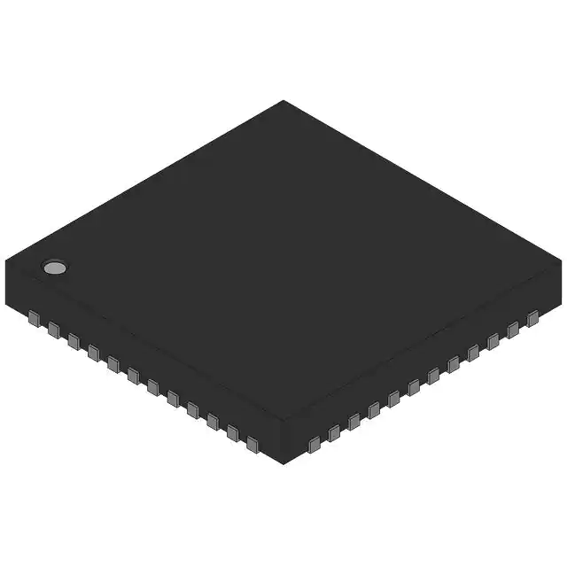
- 48-VFQFN Exposed Pad
- Datasheet:
-
 MAX2368EGM.pdf
- Description:
- DUAL-BAND QUADRATURE TRANSMITTER
- Quantity:
- Payment:

- Shipping:

Inventory:16,561
Please send an inquiry. Send us your inquiry, and we will respond immediately.
Product details
Overview
The MAX2368EGM from Maxim Integrated is a single-band cellular dual-mode quadrature transmitter IC designed for mobile phone RF front-ends. It supports cellular-band (800–1000 MHz) transmission in both FM and digital modes, delivers +7 dBm output power at RFL port with –54 dBc ACPR, provides 100 dB power control range via analog VGC input (0.5–2.6 V), and operates from +2.7 V to +5.5 V supply across –40°C to +85°C.
For engineers reviewing the MAX2368EGM datasheet, MAX2368EGM pinout, MAX2368EGM application, or MAX2368EGM equivalent, this page delivers verified functional identity, validated 48-pin QFN-EP package mapping, confirmed dual-mode cellular operation (not PCS or triple-mode), exact IF/RF frequency ranges (RFL: 800–1000 MHz; IFOUTL: 120–235 MHz), and real-world design implications of its open-collector PA driver, integrated IF/RF PLLs, and SPI/QSPI/MICROWIRE™-compatible serial interface.
Technical Context
The MAX2368EGM implements a complete transmit signal chain: differential I/Q baseband inputs feed a quadrature modulator generating IF (120–235 MHz), which is amplified by an IF VGA and routed to external filtering before SSB upconversion to RF. Its architecture includes two on-chip IF VCOs (240–470 MHz), dual synthesizers (IF and RF PLLs), and three open-collector PA driver outputs - RFL (cellular band), RFH0, and RFH1 (PCS band), though only RFL is active in MAX2368EGM's specified dual-mode cellular operation.
Control is fully digital via a 3-wire SPI-compatible bus managing charge-pump current, sideband rejection, gain balancing, standby/shutdown, and IF_BAND selection. The device uses a shared VGC pin to simultaneously control IF and RF VGA gain, enabling coordinated linearity-noise trade-offs across temperature (±1 dB gain variation) and supply voltage (2.7–3.0 V).
Key Specifications
| Parameter | Value and Actual Design Meaning |
|---|---|
| Function | Single-band cellular dual-mode (FM + digital) quadrature transmitter IC for mobile handsets |
| RFL Output Power | +7 dBm at 836 MHz with –54 dBc ACPR - meets IS-95 CDMA spectral mask requirements |
| Power Control Range | 100 dB via analog VGC (0.5–2.6 V) - enables precise transmit power ramping without digital attenuation steps |
| RFL Frequency Range | 800–1000 MHz - covers North American cellular band (824–894 MHz) and European GSM-900 (880–960 MHz) |
| IF Output Band | IFOUTL+/IFOUTL- supports 120–235 MHz low-IF operation - optimized for direct VCO FM modulation |
| Supply Voltage | +2.7 V to +5.5 V - compatible with Li-ion battery discharge profile (3.0–4.2 V) and regulated 3.3 V rails |
| Operating Temp | –40°C to +85°C - qualified for industrial-grade handset environmental stress testing |
Pinout & Package
MAX2368EGM is housed in a 48-pin QFN-EP (exposed paddle) package, thermally optimized for RF power dissipation in compact mobile phone PCB layouts. The exposed paddle must be soldered to a solid ground plane using multiple thermal vias.
| Pin/Terminal | Circuit Role | Design Meaning |
|---|---|---|
| RFL | Cellular-band RF output | Open-collector PA driver output requiring pullup inductor to VCC - forms part of output matching network; connects directly to antenna switch or SAW filter |
| IFINL+/IFINL- | Differential IF input to upconverter | 400 Ω differential input impedance, internally biased to +1.5 V - requires AC-coupled IF filter and short trace routing to minimize noise pickup |
| IFOUTL+/IFOUTL- | Differential low-IF output from VGA | 600 Ω differential output impedance, inductively pulled to VCC - active when IF_BAND = 0; feeds external IF bandpass filter before SSB mixer |
| VGC | Analog gain control input | 0.5–2.6 V input controlling both IF and RF VGA gain simultaneously - RC filtering required to suppress DAC/PDM clock spurs |
| SHDN | Global shutdown input | Logic-low assertion disables entire IC including PLLs and modulator - used for deep sleep between transmission bursts |
| TXGATE | Gated transmission control | Logic-low enables gated TX mode: RF/IF PLLs, VCOs, and registers remain active while modulator and drivers are disabled - reduces current during idle slots |
| IDLE | Standby control | Logic-low shuts down all blocks except RF PLL and registers - maintains LO lock for fast wake-up; used in discontinuous transmission (DTX) |
| CLK/DI/CS | SPI/QSPI/MICROWIRE™ interface | 3-wire serial bus (MSB-first, rising-edge clock) - programs 7×24-bit registers for PLL dividers, configuration, and operational control |
Key Features
| Feature | Design Value |
|---|---|
| Dual-mode cellular support | Enables single hardware platform to operate in both analog FM and digital (e.g., IS-95 CDMA) cellular standards without RF redesign |
| Integrated IF/RF PLLs with turbo-charge | Turbo mode boosts charge-pump current during frequency acquisition, reducing PLL lock time to <100 µs - critical for TDMA burst timing |
| Single-sideband upconverter | Eliminates need for external RF SAW filter at RFL output - reduces BOM cost and board area in space-constrained handset designs |
| 100 dB analog power control | Continuous VGC-based gain adjustment avoids quantization noise and switching transients inherent in digital step attenuators |
| Open-collector PA drivers | RFL output supports direct connection to battery rail via pullup inductor - enables efficient Class-E operation and simplifies DC biasing |
Applications
| Cellular Handset Transmitter | CDMA Mobile Phone Front-End |
|---|---|
Use Scenario: Transmit path in dual-mode (AMPS/IS-95) cellular handsets operating in 800–900 MHz bands. IC Role / Device Role / Timing Role: Quadrature transmitter converting baseband I/Q signals to RF, providing full IF-to-RF upconversion, gain control, and PA drive. Use Value: Single-chip solution eliminates discrete modulator, IF VGA, SSB mixer, and driver stages - reduces component count by ≥12 devices and saves >25 mm² PCB area. |
Use Scenario: IS-95 CDMA base station simulator or test equipment requiring calibrated RF output with high spectral purity. IC Role / Device Role / Timing Role: Precision RF signal source with programmable ACPR (–54 dBc) and stable LO synthesis for channel emulation. Use Value: On-chip IF/RF PLLs deliver phase noise of –111 dBc/Hz @ 30 kHz offset (130.38 MHz), meeting CDMA adjacent-channel leakage ratio (ACLR) requirements. |
| FM Analog Cellular Radio | Low-Power Wireless Data Modem |
Use Scenario: Legacy AMPS or TACS analog cellular infrastructure upgrade where digital compatibility is not required. IC Role / Device Role / Timing Role: FM-modulated RF transmitter using direct VCO modulation via IFOUTL ports and RFL driver output. Use Value: IFOUTL supports 120–235 MHz low-IF FM operation with ±1 dB gain flatness - enables stable deviation control without external IF amplifiers. |
Use Scenario: Industrial telemetry modem operating in unlicensed 902–928 MHz ISM band with burst transmission. IC Role / Device Role / Timing Role: Low-duty-cycle RF transmitter leveraging TXGATE for gated operation and IDLE for rapid PLL relock between packets. Use Value: Supply current drops from 164 mA (full power) to <5 mA in IDLE mode - extends battery life in sensor-node applications with 1% duty cycle. |
Equivalent & Alternatives
The following parts are listed as comparable options for similar quadrature transmitter applications.
| Alternative Part | Technical Difference | Application Difference | Selection Advice |
|---|---|---|---|
| MAX2366EGM | Dual-band, triple-mode (cellular + PCS + FM); includes RFH0/RFH1 outputs and wider IF range (120–300 MHz) | Supports PCS band (1700–2000 MHz) and triple-mode handsets; requires additional RF filtering and layout complexity | Select MAX2366EGM only if PCS band operation or multi-standard compliance is required - MAX2368EGM offers lower cost and simpler layout for cellular-only designs |
| MAX2367EGM | Single-band, single-mode (PCS only); supports RFH0/RFH1 but not RFL; IFOUTH optimized for 180–300 MHz | Targeted exclusively at PCS handsets (1850–1990 MHz); lacks cellular-band RFL output and FM mode capability | Choose MAX2367EGM for PCS-only infrastructure or test gear; MAX2368EGM is not interchangeable due to missing PCS RF outputs and different IF port activation logic |
Compared with MAX2366EGM and MAX2367EGM, the MAX2368EGM uniquely balances cellular-band performance, FM/digital dual-mode flexibility, and minimal external component count - making it the optimal choice for cost-sensitive, space-constrained 800–900 MHz handset designs where PCS support is unnecessary.
Availability
MAX2368EGM is available at Aetrix Electronics and suitable for cellular handset manufacturing, CDMA infrastructure test equipment, FM radio transmitters, and low-power wireless data modems requiring stable component supply and long-term production continuity.
Supply support for MAX2368EGM includes scheduled delivery planning, volume procurement assistance, BOM continuity management, traceable sourcing, and lifecycle availability coordination for OEM customers, industrial embedded developers, connected-device designers, and electronics production programs.
Manufacturer
Maxim Integrated (now part of Analog Devices) is a U.S.-based semiconductor company specializing in high-performance analog and mixed-signal ICs for communications, computing, and industrial markets.
The MAX236x family was developed specifically for cellular phone RF front-ends, emphasizing integration density, power efficiency, and programmability to reduce handset bill-of-materials and accelerate time-to-market for dual-mode mobile platforms.
FAQ
What is the primary function of the MAX2368EGM in a cellular handset design?
The MAX2368EGM serves as the complete quadrature transmitter IC in cellular handsets, accepting differential I/Q baseband signals and performing IF modulation, IF-to-RF upconversion, variable-gain amplification, and PA driver functionality for the 800–1000 MHz cellular band. Its dual-mode capability supports both FM analog and IS-95 CDMA digital transmission within a single chip, eliminating discrete modulators, mixers, and driver stages in the RF front-end.
Does the MAX2368EGM support PCS band operation like the MAX2366EGM?
No, the MAX2368EGM does not support PCS band operation. It is explicitly specified for single-band cellular dual-mode (FM + digital) operation only, with active RF output limited to the RFL port (800–1000 MHz). Unlike the MAX2366EGM, it lacks functional RFH0 and RFH1 outputs and does not enable the IFOUTH+/- ports - confirmed by its ordering information, pin description, and electrical characteristics tables in the official datasheet.
What is the role of the VGC pin on the MAX2368EGM, and what voltage range should be applied?
The VGC pin on the MAX2368EGM is the analog voltage-controlled gain input that simultaneously adjusts both the IF VGA and RF VGA gain stages. A voltage between +0.5 V and +2.6 V must be applied to achieve the full 100 dB power control range. Applying voltages outside this range may cause gain saturation or loss of linearity; typical operating points include +2.5 V for maximum output (+7 dBm) and +0.5 V for minimum output (–93 dBm).
How does the MAX2368EGM handle power management during transmission bursts?
The MAX2368EGM provides three hierarchical power states: SHDN (full shutdown), TXGATE (gated TX with PLLs active), and IDLE (standby with RF PLL locked). During TDMA bursts, TXGATE allows rapid turn-on of the modulator and drivers while maintaining LO lock, reducing wake-up latency to <50 µs. In IDLE mode, supply current drops to <5 mA while preserving RF PLL lock - enabling fast resumption of transmission without full PLL reacquisition.
Can the MAX2368EGM be used without external IF filtering?
No, external IF filtering is mandatory for the MAX2368EGM. Its IFOUTL+/- ports deliver a 120–235 MHz differential IF signal intended for connection to an external bandpass filter before feeding the SSB upconverter. Omitting this filter causes image and harmonic energy to fold into the RF band, degrading ACPR beyond the specified –54 dBc and violating FCC spectral mask requirements. The device's "single sideband upconverter" eliminates the *RF* SAW filter, not the IF filter.
MAX2368EGM Specifications
- Product attributes
- Attribute value
- Manufacturer:
- Analog Devices Inc./Maxim Integrated
- Series:
- -
- Package/Case:
- 48-VFQFN Exposed Pad
- Packaging:
- Bulk
- Product Status:
- Active
- Programmable:
- Not Verified
- Frequency:
- 1.7GHz ~ 2GHz
- Applications:
- WAN, Wireless LAN
- Modulation or Protocol:
- CDMA
- Data Rate (Max):
- -
- Power - Output:
- 6.6dBm ~ 12dBm
- Current - Transmitting:
- 114mA ~ 132mA
- Data Interface:
- SPI
- Antenna Connector:
- -
- Memory Size:
- -
- Features:
- PLL Frequency Synthesizer and PA
- Voltage - Supply:
- 2.7V ~ 3V
- Operating Temperature:
- -40°C ~ 85°C
- Grade:
- -
- Qualification:
- -
- Mounting Type:
- Surface Mount
- Supplier Device Package:
- 48-QFN (7x7)
MAX2368EGM FAQ
1.How can I place an order for MAX2368EGM through Aetrix?
Please submit a Request for Quotation (RFQ) for MAX2368EGM on Aetrix. Our sales agent will provide a competitive quotation and guide you through the order confirmation once you accept the terms.
2.Are the price and stock information for MAX2368EGM reliable?
The price and inventory of MAX2368EGM are updated periodically and may fluctuate due to market conditions. Stock and pricing data are typically refreshed every 24 hours. Quotation validity for MAX2368EGM is usually 5 days.
3.What payment methods are accepted for MAX2368EGM?
We accept Wire Transfer, PayPal, Credit Card, Western Union, MoneyGram, and Escrow for MAX2368EGM transactions.
Note: Certain payment methods may incur a processing fee.
4.How is shipping managed for MAX2368EGM?
MAX2368EGM orders can be shipped via leading logistics carriers, including DHL, UPS, FedEx, TNT, or Registered Mail.
Once your MAX2368EGM order is processed, you will receive an email with the shipment details and tracking number.
Note: Tracking information may take up to 24 hours to appear. Express delivery typically takes 3–5 business days.
5.How can I obtain technical support or documentation for MAX2368EGM?
For technical support, including MAX2368EGM datasheets, pinout diagrams, or application guidance, please contact our engineering support team. They can provide detailed documentation and assistance for your MAX2368EGM requirements.
6.How does Aetrix verify that MAX2368EGM is sourced from the original manufacturer or authorized distributors?
All MAX2368EGM products on Aetrix are procured from qualified distributors and authorized channels. Our dedicated quality assurance team conducts strict verification, including traceability checks and, if necessary, third-party testing. This ensures that MAX2368EGM meets industry standards.
7.What is the process for return or replacement of MAX2368EGM?
All MAX2368EGM units undergo pre-shipment inspection (PSI). If there is an issue with MAX2368EGM, returns or replacements are accepted under the following conditions:
1.Quantity discrepancies, incorrect items, or visible external defects (such as breakage or corrosion), acknowledged by Aetrix.
2.The issue is reported within 90 days of delivery.
3.The MAX2368EGM part is unused and in its original packaging.
Return procedure for MAX2368EGM:
1.Submit a request within 90 days.
2.Obtain a Return Material Authorization (RMA) from Aetrix.
MAX2368EGM Tags

-
MICRF113YM6-TR
Microchip Technology
-
PIC12LF1840T39AT-I/ST
Microchip Technology

-
MAX41460GUB+T
Analog Devices Inc./Maxim Integrated
-
SX1230I066TRT
Semtech Corporation
-
SI4010-C2-GS
Silicon Labs
-
CC1070RSQR
Texas Instruments
-
TXM-418-LR
TE Connectivity Linx
-
TXM-433-LR
TE Connectivity Linx
-
TXM-418-KH3
TE Connectivity Linx

-
TX7332ZBX
Texas Instruments
-
MICRF114T-I/OT
Microchip Technology
-
MICRF112YMM-TR
Microchip Technology
Tech Hub

A practical engineering guide to 3.3V and 5V logic compatibility, input thresholds, resistor dividers, translator ICs, MOSFET level shifting, I2C pull-ups, timing limits and power-sequencing risks.

The 74HC595 uses push-pull logic outputs, while the TPIC6B595 uses 50 V open-drain DMOS sinks for higher-power loads. This guide compares timing, current limits, 3.3 V interfacing, load wiring, thermal…

The 74HC595 converts serial data into eight stable parallel outputs. This guide covers pin functions, shift and storage timing, OE and MR behavior, drive-current limits, cascading, voltage compatibilit…

A technical comparison of level-sensitive latches and edge-triggered flip-flops, covering timing windows, setup and hold limits, master–slave operation, time borrowing, race-through, HDL inference and…

A D latch stores one bit while Enable controls when data can pass. This reference covers gate-level operation, truth tables, transparency, setup and hold timing, LE versus OE, common ICs and practical …

An SR latch stores one bit through cross-coupled feedback. This engineering reference covers NOR and NAND implementations, truth tables, forbidden-state recovery, gated operation, switch debouncing, fa…

Latch circuits retain one bit through feedback. This technical reference covers SR and D latches, truth tables, transparency, timing limits, latch-versus-flip-flop behavior, applications and common log…

An engineering guide to LED driver operation, constant-current and constant-voltage outputs, linear and switching topologies, dimming, IC selection, calculations, replacement compatibility, and fault c…

Operational amplifier guide covering op amp basics, feedback, ideal vs real op amps, common configurations, buffer circuits, offset, bias current, gain-bandwidth, slew rate, rail-to-rail limits and sel…

Jumper cables guide covering safe connection order, red and black clamp placement, final ground connection, cable gauge, length, clamp quality, copper vs CCA cables, jump starter comparison and battery…


