
 My Inquiry
 My Account


Analog Devices Inc./Maxim Integrated MAX2670GTB/V+T
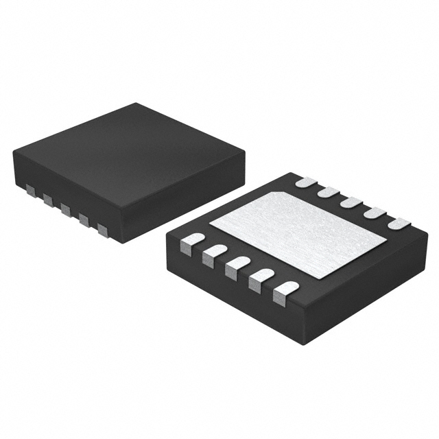
- Part No.:
- MAX2670GTB/V+T
- Manufacturer:
- Analog Devices Inc./Maxim Integrated
- Category:
- RF Front End (LNA + PA)
- Package:
- 10-WFDFN Exposed Pad
- Datasheet:
-
 MAX2670GTB/V+T.pdf
- Description:
- IC AMP GPS/GNSS FRONTEND 10TDFN
- Quantity:
- Payment:

- Shipping:

Inventory:1,702
Please send an inquiry. Send us your inquiry, and we will respond immediately.
Product details
Overview
MAX2670GTB/V+T from Maxim Integrated is an AEC-Q100 qualified GPS/GNSS front-end amplifier IC comprising two cascaded SiGe low-noise amplifier stages, delivering 34.8dB typical cascaded gain at 1575MHz with 1.0dB noise figure on AMP1 and 2.0dB on AMP2, operating from 3.0V to 5.5V supply and designed for automotive antenna modules compensating cable loss between GPS antenna and receiver.
For engineers reviewing the MAX2670GTB/V+T datasheet, MAX2670GTB/V+T pinout, MAX2670GTB/V+T application, or MAX2670GTB/V+T equivalent, this page provides verified technical context, validated pin functions, confirmed GNSS-band performance metrics, and real-world automotive/marine system integration guidance - all specific to the -V (automotive-grade) variant in 10-pin TDFN-EP package.
Technical Context
The MAX2670GTB/V+T integrates two unconditionally stable LNA stages optimized for 1575MHz GNSS operation: AMP1 features internal DC-blocking and 50Ω output matching but requires external input matching; AMP2 provides dual-role RFOUT2/VCC pin with integrated bias-T functionality and a 3.4dB gain step controlled by GAIN_SELECT (pin 7).
It employs advanced SiGe process technology, supports direct DC injection via RFOUT2/VCC (pin 5) or alternate supply via EXTCAP/ALT_VCC (pin 4), and maintains stable gain and noise performance across -40°C to +105°C ambient temperature - meeting AEC-Q100 Grade 2 requirements for automotive deployment.
Key Specifications
| Parameter | Value and Actual Design Meaning |
|---|---|
| Operating Frequency | 1575MHz - precisely aligned to GPS L1, GLONASS G1, Galileo E1, and BeiDou B1 bands. |
| Cascaded Gain | 34.8dB typical - enables compensation of up to ~35dB coaxial cable loss in automotive antenna feedlines. |
| Noise Figure (AMP1) | 1.0dB - minimizes degradation of GPS receiver sensitivity when placed directly after antenna. |
| Supply Voltage Range | 3.0V to 5.5V - compatible with standard automotive 3.3V or 5V power rails without external regulation. |
| Supply Current | 25mA typical at +25°C - balances low power consumption with high linearity for continuous GNSS tracking. |
| Gain Step Control | −3.4dB step via GAIN_SELECT pin - allows dynamic adjustment for varying cable lengths or filter insertion losses. |
| Temperature Range | −40°C to +105°C - certified AEC-Q100 Grade 2, supporting under-hood and dashboard mounting. |
Pinout & Package
MAX2670GTB/V+T is housed in a lead-free, RoHS-compliant 10-pin TDFN-EP package (3mm × 3mm), with exposed thermal pad requiring soldering to PCB ground plane for optimal thermal dissipation and RF performance.
| Pin/Terminal | Circuit Role | Design Meaning |
|---|---|---|
| 1 RFIN2 | AMP2 Input | Internally DC-blocked and 50Ω matched; designed to accept filtered signal from SAW/ceramic bandpass filter. |
| 2,3,8,9 GND | Ground Reference | Multiple dedicated ground pins minimize inductance and ensure stable biasing and isolation between stages. |
| 4 EXTCAP/ALT_VCC | Alternate Supply Input | Accepts external DC supply to bypass bias-T; also serves as connection point for smoothing capacitor. |
| 5 RFOUT2/VCC | AMP2 Output & Power Input | Dual-function pin: delivers amplified RF output while accepting DC supply via bias-T (no separate VCC trace needed). |
| 6 RFIN1 | AMP1 Input | Requires external DC-blocking capacitor and impedance matching network for optimal noise/gain trade-off. |
| 7 GAIN_SELECT | Gain Mode Control | Open = high-gain mode; shorted to GND = −3.4dB reduced gain; internal pull-up ensures default high-gain operation. |
| 10 RFOUT1 | AMP1 Output | Internally DC-blocked and 50Ω matched; drives interstage filter before AMP2 input. |
| EP (Exposed Pad) | Thermal & Electrical Ground | Must be soldered to solid ground plane for thermal management, RF stability, and ESD protection path. |
Key Features
| Feature | Design Value |
|---|---|
| Integrated I/O Matching | 50Ω output matching on RFOUT1, RFIN2, and RFOUT2/VCC eliminates need for external matching networks on those ports. |
| Shared RF/DC Pin (RFOUT2/VCC) | Reduces system component count and PCB area by combining RF output and DC supply on single pin using bias-T architecture. |
| Two-Stage Cascaded Architecture | Enables flexible placement of bandpass filter between stages to improve overall system noise figure and out-of-band rejection. |
| AEC-Q100 Qualification | Validated for automotive environments including temperature cycling, vibration, and long-term reliability under harsh conditions. |
| ESD Protection | ±2kV HBM rating protects against handling damage during assembly and field service in vehicle electronics. |
Applications
| Automotive Telematics Antenna Modules | Marine GNSS Active Antennas |
|---|---|
Use Scenario: Mounted on vehicle roof or dashboard, receiving GPS/GNSS signals through coaxial cable to head unit or ADAS ECU. IC Role / Device Role / Timing Role: Front-end LNA compensating 3–10m cable loss while preserving C/N₀ ratio for accurate position fix. Use Value: Enables reliable cold-start TTFF & sub-3m horizontal accuracy even with long cable runs and metal-rich vehicle body interference. | Use Scenario: Integrated into marine chartplotter antenna mast assemblies exposed to salt spray and wide temperature swings. IC Role / Device Role / Timing Role: First-stage amplification immediately after antenna element, rejecting out-of-band cellular/LTE interference before filtering. Use Value: Maintains >30dB image rejection and <1.2dB NF over −40°C to +85°C, ensuring consistent navigation during coastal and open-ocean operation. |
| ADAS Positioning Subsystems | Emergency Call (eCall) GNSS Receivers |
Use Scenario: Embedded in lane-departure warning or adaptive cruise control modules requiring precise real-time location. IC Role / Device Role / Timing Role: High-linearity LNA stage enabling simultaneous multi-constellation (GPS+Galileo+BeiDou) signal acquisition under multipath urban canyon conditions. Use Value: Delivers OIP3 ≥16dBm and IIP3 ≥−12dBm, preventing intermodulation distortion from nearby LTE base stations. | Use Scenario: Installed in vehicle emergency call telematics control units (TCUs) mandated by EU eCall regulation. IC Role / Device Role / Timing Role: AEC-Q100 qualified front-end amplifier ensuring GNSS signal integrity during crash-induced power transients and battery voltage sag. Use Value: Operates down to 3.0V supply and sustains 25mA current draw across full automotive temperature range, guaranteeing position reporting within 100ms of activation. |
Equivalent & Alternatives
The following parts are listed as comparable options for similar GPS/GNSS front-end amplifier applications.
| Alternative Part | Technical Difference | Application Difference | Selection Advice |
|---|---|---|---|
| Qorvo QM11025 | Single-stage LNA (19dB gain), no gain step, 1.2dB NF, 3.3V-only supply. | Lacks cascaded architecture and interstage filter flexibility; suited for space-constrained single-LNA designs. | Select QM11025 only if system uses external pre-filtering and requires minimal footprint; MAX2670GTB/V+T preferred for cable-loss compensation. |
| Skyworks SKY65168-396LF | 32dB gain, 1.3dB NF, no integrated bias-T, requires separate VCC routing and external matching. | Higher board-level design effort due to missing integrated matching and shared RF/DC pin functionality. | Choose SKY65168-396LF only when legacy layout lacks bias-T support; MAX2670GTB/V+T reduces BOM count and improves thermal robustness. |
Compared with QM11025 and SKY65168-396LF, the MAX2670GTB/V+T uniquely combines AEC-Q100 qualification, dual-LNA architecture with programmable gain step, and integrated bias-T functionality - making it the only solution that simultaneously satisfies automotive reliability, GNSS signal fidelity, and simplified RF front-end integration.
Availability
MAX2670GTB/V+T is available at Aetrix Electronics and suitable for automotive telematics, marine navigation systems, and ADAS positioning subsystems requiring stable component supply across extended temperature ranges and long production lifecycles.
Supply support for MAX2670GTB/V+T includes scheduled delivery planning, volume procurement assistance, BOM continuity management, traceable sourcing, and lifecycle availability coordination for OEM customers, industrial embedded developers, connected-device designers, and electronics production programs.
Manufacturer
Maxim Integrated (now part of Analog Devices) is a U.S.-based semiconductor company specializing in high-performance analog, mixed-signal, and RF solutions for automotive, industrial, and communications markets.
The MAX2670 product line delivers highly integrated, AEC-Q100 qualified GPS/GNSS front-end amplifiers targeting automotive antenna modules where cable loss compensation, thermal stability, and ESD robustness are critical design constraints.
FAQ
What is the primary function of the MAX2670GTB/V+T in a GPS/GNSS system?
The MAX2670GTB/V+T serves as a two-stage front-end low-noise amplifier specifically engineered to compensate for signal attenuation in coaxial cables connecting GPS/GNSS antennas to receivers. Its 34.8dB cascaded gain, 1.0dB AMP1 noise figure, and AEC-Q100 qualification make it ideal for automotive and marine applications where signal integrity must be preserved across temperature extremes and mechanical stress. The MAX2670GTB/V+T enables reliable satellite acquisition even with long cable runs and metallic vehicle body interference.
How does the GAIN_SELECT pin (pin 7) affect MAX2670GTB/V+T operation?
The GAIN_SELECT pin on the MAX2670GTB/V+T controls a 3.4dB gain step in the second amplifier stage: when left open (default), the device operates in high-gain mode; when shorted to ground, gain reduces by −3.4dB. This feature allows system designers to adapt amplifier performance to varying cable lengths, filter insertion losses, or regulatory output power limits without changing hardware. The internal pull-up resistor ensures fail-safe high-gain behavior if the pin is unconnected, and MAX2670GTB/V+T maintains stable operation across −40°C to +105°C in both modes.
Can MAX2670GTB/V+T operate without an external bias-T circuit?
Yes - the MAX2670GTB/V+T eliminates the need for an external bias-T by integrating dual functionality into the RFOUT2/VCC pin (pin 5): it delivers the amplified RF output while simultaneously accepting DC supply voltage. Alternatively, power can be applied directly to the EXTCAP/ALT_VCC pin (pin 4), bypassing the RF path entirely. This flexibility simplifies PCB layout, reduces component count, and enhances reliability in automotive GNSS modules where space and failure modes are critical concerns. The MAX2670GTB/V+T's internal bias separation ensures clean RF output regardless of supply method.
What package type and thermal considerations apply to MAX2670GTB/V+T?
The MAX2670GTB/V+T uses a 10-pin TDFN-EP package (3mm × 3mm) with an exposed thermal pad that must be soldered to the PCB ground plane. This construction provides low thermal resistance for efficient heat dissipation during continuous 25mA operation and ensures stable RF performance across −40°C to +105°C. Layout guidelines require short, controlled-impedance traces to RFIN1, proper decoupling near pin 4, and direct grounding of pin 7 for low-gain mode - all critical for maintaining the MAX2670GTB/V+T's specified noise figure and gain flatness in production systems.
Is MAX2670GTB/V+T compatible with multi-constellation GNSS signals beyond GPS L1?
Yes - the MAX2670GTB/V+T is designed for full GNSS frequency coverage centered at 1575MHz, supporting GPS L1 (1575.42MHz), GLONASS G1 (1602MHz ± 0.5625MHz), Galileo E1 (1575.42MHz), and BeiDou B1 (1561.098MHz). Its gain flatness, noise figure, and IP3 performance are characterized across this band, and its AEC-Q100 qualification ensures consistent operation in multi-constellation environments subject to automotive thermal and EMI stress. System designers can rely on the MAX2670GTB/V+T to preserve signal integrity for all major global navigation satellite systems without retuning.
MAX2670GTB/V+T Specifications
- Product attributes
- Attribute value
- Manufacturer:
- Analog Devices Inc./Maxim Integrated
- Series:
- -
- Packaging:
- Tape & Reel (TR)
- Product Status:
- Active
- RF Type:
- GPS/GNSS
- Frequency:
- 1575MHz
- Features:
- -
- Grade:
- -
- Qualification:
- -
- Supplier Device Package:
- 10-TDFN (3x3)
MAX2670GTB/V+T FAQ
1.How can I place an order for MAX2670GTB/V+T through Aetrix?
Please submit a Request for Quotation (RFQ) for MAX2670GTB/V+T on Aetrix. Our sales agent will provide a competitive quotation and guide you through the order confirmation once you accept the terms.
2.Are the price and stock information for MAX2670GTB/V+T reliable?
The price and inventory of MAX2670GTB/V+T are updated periodically and may fluctuate due to market conditions. Stock and pricing data are typically refreshed every 24 hours. Quotation validity for MAX2670GTB/V+T is usually 5 days.
3.What payment methods are accepted for MAX2670GTB/V+T?
We accept Wire Transfer, PayPal, Credit Card, Western Union, MoneyGram, and Escrow for MAX2670GTB/V+T transactions.
Note: Certain payment methods may incur a processing fee.
4.How is shipping managed for MAX2670GTB/V+T?
MAX2670GTB/V+T orders can be shipped via leading logistics carriers, including DHL, UPS, FedEx, TNT, or Registered Mail.
Once your MAX2670GTB/V+T order is processed, you will receive an email with the shipment details and tracking number.
Note: Tracking information may take up to 24 hours to appear. Express delivery typically takes 3–5 business days.
5.How can I obtain technical support or documentation for MAX2670GTB/V+T?
For technical support, including MAX2670GTB/V+T datasheets, pinout diagrams, or application guidance, please contact our engineering support team. They can provide detailed documentation and assistance for your MAX2670GTB/V+T requirements.
6.How does Aetrix verify that MAX2670GTB/V+T is sourced from the original manufacturer or authorized distributors?
All MAX2670GTB/V+T products on Aetrix are procured from qualified distributors and authorized channels. Our dedicated quality assurance team conducts strict verification, including traceability checks and, if necessary, third-party testing. This ensures that MAX2670GTB/V+T meets industry standards.
7.What is the process for return or replacement of MAX2670GTB/V+T?
All MAX2670GTB/V+T units undergo pre-shipment inspection (PSI). If there is an issue with MAX2670GTB/V+T, returns or replacements are accepted under the following conditions:
1.Quantity discrepancies, incorrect items, or visible external defects (such as breakage or corrosion), acknowledged by Aetrix.
2.The issue is reported within 90 days of delivery.
3.The MAX2670GTB/V+T part is unused and in its original packaging.
Return procedure for MAX2670GTB/V+T:
1.Submit a request within 90 days.
2.Obtain a Return Material Authorization (RMA) from Aetrix.
MAX2670GTB/V+T Tags
-
RFX2401C
Skyworks Solutions Inc.
.jpg)
-
NRF21540-QDAA-R
Nordic Semiconductor ASA
-
NRF21540-QDAA-R7
Nordic Semiconductor ASA
-
RFX2411N
Skyworks Solutions Inc.
-
SE2438T-R
Skyworks Solutions Inc.
-
SKY66118-11
Skyworks Solutions Inc.
-
SKY85712-21
Skyworks Solutions Inc.

-
SKY85329-11
Skyworks Solutions Inc.
-
SKY66422-11
Skyworks Solutions Inc.

-
SKY66119-11
Skyworks Solutions Inc.
-
NJG1156PCD-TE1
Nisshinbo Micro Devices Inc.
-
SE2435L-R
Skyworks Solutions Inc.
Tech Hub

A practical engineering guide to 3.3V and 5V logic compatibility, input thresholds, resistor dividers, translator ICs, MOSFET level shifting, I2C pull-ups, timing limits and power-sequencing risks.

The 74HC595 uses push-pull logic outputs, while the TPIC6B595 uses 50 V open-drain DMOS sinks for higher-power loads. This guide compares timing, current limits, 3.3 V interfacing, load wiring, thermal…

The 74HC595 converts serial data into eight stable parallel outputs. This guide covers pin functions, shift and storage timing, OE and MR behavior, drive-current limits, cascading, voltage compatibilit…

A technical comparison of level-sensitive latches and edge-triggered flip-flops, covering timing windows, setup and hold limits, master–slave operation, time borrowing, race-through, HDL inference and…

A D latch stores one bit while Enable controls when data can pass. This reference covers gate-level operation, truth tables, transparency, setup and hold timing, LE versus OE, common ICs and practical …

An SR latch stores one bit through cross-coupled feedback. This engineering reference covers NOR and NAND implementations, truth tables, forbidden-state recovery, gated operation, switch debouncing, fa…

Latch circuits retain one bit through feedback. This technical reference covers SR and D latches, truth tables, transparency, timing limits, latch-versus-flip-flop behavior, applications and common log…

An engineering guide to LED driver operation, constant-current and constant-voltage outputs, linear and switching topologies, dimming, IC selection, calculations, replacement compatibility, and fault c…

Operational amplifier guide covering op amp basics, feedback, ideal vs real op amps, common configurations, buffer circuits, offset, bias current, gain-bandwidth, slew rate, rail-to-rail limits and sel…

Jumper cables guide covering safe connection order, red and black clamp placement, final ground connection, cable gauge, length, clamp quality, copper vs CCA cables, jump starter comparison and battery…


