
 My Inquiry
 My Account


Analog Devices Inc./Maxim Integrated MAX2982GCD/V+T
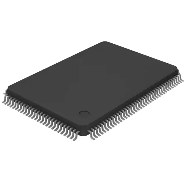
- Part No.:
- MAX2982GCD/V+T
- Manufacturer:
- Analog Devices Inc./Maxim Integrated
- Category:
- Telecom
- Package:
- 128-LQFP
- Datasheet:
-
 MAX2982GCD/V+T.pdf
- Description:
- IC TELECOM INTERFACE 128LQFP
- Quantity:
- Payment:

- Shipping:

Inventory:3,668
Please send an inquiry. Send us your inquiry, and we will respond immediately.
Product details
Overview
MAX2982GCD/V+T from Maxim Integrated is an industrial broadband power-line transceiver integrating MAC and PHY layers in a single 128-pin LQFP device. It delivers up to 14Mbps data rate using 84-carrier OFDM, supports HomePlug 1.0 compliance, operates from –40°C to +105°C, and features integrated ARM946E-S™ processor and DES encryption for secure communication in harsh industrial line environments.
For engineers reviewing the MAX2982GCD/V+T datasheet, MAX2982GCD/V+T pinout, MAX2982GCD/V+T application, or MAX2982GCD/V+T equivalent, this page provides verified technical context, interface timing constraints, thermal performance limits, spectral shaping capability, and real-world deployment guidance for power-line communication systems requiring robust SNR resilience and regulatory flexibility.
Technical Context
The MAX2982GCD/V+T implements a full HomePlug 1.0–compliant PHY layer with 84-carrier OFDM modulation, supporting DBPSK, DQPSK (1/2 and 3/4 FEC), and ROBO mode delivering –1dB SNR performance. Its integrated ARM946E-S™ core enables field-upgradable firmware, spectral notching, and automatic channel adaptation.
It interfaces via IEEE 802.3 MII/RMII, synchronous FIFO, UART, and 10/100 Ethernet MAC - all operating at VDD33 = 3.3V and VDD12 = 1.2V. The device includes a calibrated on-die temperature sensor (7 mV/°C, ±5°C accuracy) and advanced narrowband interference rejection circuitry for industrial EMI resilience.
Key Specifications
| Parameter | Value and Actual Design Meaning |
|---|---|
| Data Rate | Up to 14Mbps - maximum throughput for high-speed industrial telemetry over AC power lines. |
| OFDM Carriers | 84 carriers - enables frequency-domain adaptability across noisy power-line channels. |
| Operating Temp | –40°C to +105°C - qualified for under-hood, factory-floor, and outdoor industrial deployments. |
| Supply Voltages | VDD33 = 3.0–3.6V; VDD12 = 1.14–1.26V - dual-rail operation ensures low-power digital logic and noise-isolated analog core. |
| Encryption | 56-bit DES with key management - hardware-accelerated confidentiality for secure PLC network traffic. |
| Interface Support | MII/RMII, synchronous FIFO, UART - glue-free connectivity to host microcontrollers or Ethernet switches without external logic. |
| Frequency Band | 4.49MHz to 20.7MHz - optimized spectral placement to avoid AM radio and legacy PLC bands. |
Pinout & Package
MAX2982GCD/V+T is housed in a 128-pin, lead-free LQFP package (14mm × 14mm, 0.4mm pitch) with exposed thermal pad. Power supply pins are distributed across multiple corners for low-impedance decoupling; DGND and AVSS are separately routed to minimize digital/analog coupling.
| Pin/Terminal | Circuit Role | Design Meaning |
|---|---|---|
| ETHTXD[0]–[3]/MIIDAT[0–3] | MII/FIFO Transmit Data Bus | 4-bit parallel interface for 10/100 Ethernet MAC output or synchronous FIFO write path. |
| ETHRXD[0]–[3]/MIIDAT[4–7] | MII/FIFO Receive Data Bus | 4-bit parallel input for Ethernet frame reception or FIFO read data stream. |
| AFECLK | Analog Front-End Clock Output | 50MHz clock driving MAX2981 AFE; critical for precise DAC/ADC sampling synchronization. |
| AFEDAD[0–9] | AFE DAC/ADC Interface | 10-bit bidirectional analog data bus connecting to companion MAX2981 for line driver/receiver control. |
| TEMP_SENS | Analog Temperature Sensor Output | Calibrated voltage output (465mV @ 25°C, 7mV/°C slope) for system thermal monitoring without external sensors. |
| GPIO[0–23] | Configurable I/O Bank | 24 pins supporting boot configuration, LED signaling, nonvolatile memory interface, and AFE control signals. |
Key Features
| Feature | Design Value |
|---|---|
| Integrated ARM946E-S™ Core | Enables field-upgradable firmware, dynamic spectral shaping, and real-time interference mitigation without host CPU dependency. |
| ROBO Mode Operation | Delivers –1dB SNR threshold for reliable link establishment in high-noise industrial power-line environments. |
| Advanced Narrowband Rejection | Hardware-based jammer suppression preserves throughput in presence of persistent narrowband interference (e.g., VHF radios). |
| HomePlug 1.0 Compliance | Ensures interoperability with certified power-line networking infrastructure and avoids protocol-level integration risk. |
| On-Chip Temperature Sensor | ±5°C accuracy over –40°C to +105°C enables thermal derating and fanless design validation for sealed enclosures. |
Applications
| Industrial Motor Control | Remote SCADA Monitoring |
|---|---|
Use Scenario: Real-time torque and position feedback from variable-frequency drives over existing 3-phase AC wiring in manufacturing cells. IC Role / Device Role / Timing Role: Power-line transceiver handling MAC/PHY layer, providing deterministic latency (<10ms round-trip) and adaptive retransmission. Use Value: Eliminates dedicated RS-485 cabling; leverages installed power infrastructure while maintaining >99.9% frame integrity under motor switching noise. |
Use Scenario: Connecting distributed RTUs in oil/gas pipeline monitoring stations where fiber or cellular backhaul is cost-prohibitive. IC Role / Device Role / Timing Role: Secure broadband modem enabling encrypted 10/100 Ethernet bridging over shared MV/LV distribution lines. Use Value: Achieves 14Mbps aggregate bandwidth across 5km line segments with automatic channel adaptation to aging cable impedance shifts. |
| Building Automation Systems | Smart Grid Substation Comms |
Use Scenario: Interconnecting HVAC controllers, lighting nodes, and fire panels in commercial high-rises using existing electrical conduits. IC Role / Device Role / Timing Role: HomePlug 1.0–compliant transceiver acting as edge node bridge between BACnet/IP and power-line physical layer. Use Value: Reduces retrofit installation time by >70%; supports multicast group addressing for synchronized lighting scene updates. |
Use Scenario: Communication between protective relays and substation gateways over medium-voltage distribution feeders. IC Role / Device Role / Timing Role: Industrial-grade PLC modem with AEC-Q100–grade qualification ensuring reliability during fault-induced transients. Use Value: Maintains secure command-and-control link during lightning-induced surges, validated to IEC 61000-4-5 Level 4 (4kV) |
Equivalent & Alternatives
The following parts are listed as comparable options for similar power-line transceiver applications.
| Alternative Part | Technical Difference | Application Difference | Selection Advice |
|---|---|---|---|
| MAX2981GCD/V+T | Companion analog front-end only; lacks integrated MAC/PHY and ARM processor. | Requires separate digital baseband IC; suitable only when MAX2982 is unavailable or system requires discrete signal chain optimization. | Select MAX2981GCD/V+T only when designing custom PHY layer or implementing non-HomePlug protocols. |
| ST7580 | Single-chip PRIME-compliant PLC transceiver; 1.2–25MHz band; no integrated MCU or DES engine. | Targeted at smart metering (IEC 61334-5-1); lacks industrial temperature range and ROBO mode robustness. | Choose ST7580 for utility-side AMI deployments where PRIME standard compliance is mandatory and ambient temperature stays <85°C. |
Compared with MAX2982GCD/V+T, MAX2981GCD/V+T requires external digital baseband and offers no encryption or firmware upgradability, while ST7580 targets metering-specific standards and lacks the industrial thermal margin and SNR resilience of the MAX2982GCD/V+T.
Availability
MAX2982GCD/V+T is available at Aetrix Electronics and suitable for industrial motor control, remote SCADA monitoring, building automation systems, and smart grid substation communications requiring stable component supply across extended temperature and long product lifecycles.
Supply support for MAX2982GCD/V+T includes scheduled delivery planning, volume procurement assistance, BOM continuity management, traceable sourcing, and lifecycle availability coordination for OEM customers, industrial embedded developers, connected-device designers, and electronics production programs.
Manufacturer
Maxim Integrated (now part of Analog Devices) designs precision analog, mixed-signal, and power management ICs for industrial, automotive, and communications markets.
The MAX2982GCD/V+T belongs to Maxim's industrial power-line communication product line, engineered specifically for robust, secure, high-throughput data transmission over noisy AC and DC power distribution networks.
FAQ
What is the primary function of the MAX2982GCD/V+T in a power-line communication system?
The MAX2982GCD/V+T serves as a fully integrated HomePlug 1.0–compliant power-line transceiver, combining MAC and PHY layers with an ARM946E-S™ processor. It handles OFDM modulation/demodulation, forward error correction, spectral shaping, and DES encryption - enabling secure, high-speed (up to 14Mbps) data transmission over AC/DC power lines without requiring external baseband logic. Its role is central to establishing and maintaining reliable PLC links in industrial settings.
Does the MAX2982GCD/V+T require an external analog front-end, and if so, which one is recommended?
Yes, the MAX2982GCD/V+T requires an external analog front-end to drive and receive signals from the power line. The MAX2981GCD/V+T is the designated companion AFE, providing integrated line driver, receiver, AGC, and LPF/HPF filtering. The MAX2982GCD/V+T communicates with the MAX2981GCD/V+T via the 10-bit AFEDAD[0–9] bus and control signals including AFECLK, AFETXEN, and AFEREN - forming a complete, validated PLC solution.
What are the absolute maximum ratings for power supply voltages on the MAX2982GCD/V+T?
The MAX2982GCD/V+T specifies absolute maximum ratings of VDD33 to DGND = –0.3V to +4.0V, VDD12 to DGND = –0.3V to +1.5V, and AVDD to AVSS = –0.5V to +1.5V. Exceeding these may cause permanent damage. Recommended operating ranges are tighter: VDD33 = 3.0–3.6V and VDD12 = 1.14–1.26V. These margins ensure safe operation during transient events while maintaining signal integrity across digital and analog domains.
How does the ROBO mode in the MAX2982GCD/V+T improve communication reliability?
ROBO mode in the MAX2982GCD/V+T is a robust OFDM operational mode delivering –1dB SNR performance at frame error rates of 10⁻⁴. It achieves this through aggressive forward error correction and reduced symbol rate, making it uniquely suited for industrial environments with high impulse noise (e.g., motor commutation, relay switching). Unlike standard DQPSK modes, ROBO maintains link stability even when narrowband jammers or deep frequency nulls degrade channel quality - a key differentiator for mission-critical PLC deployments.
Can the MAX2982GCD/V+T operate without an external crystal oscillator?
No, the MAX2982GCD/V+T requires an external 30MHz fundamental-mode crystal connected between XIN (pin 105) and XOUT (pin 106) to generate its internal clocks. The crystal must meet load capacitance and stability specifications outlined in the datasheet; no internal RC oscillator is provided. This external reference ensures precise timing alignment between the digital baseband, AFE interface, and Ethernet MAC - essential for HomePlug 1.0 compliance and low-jitter OFDM symbol generation.
MAX2982GCD/V+T Specifications
- Product attributes
- Attribute value
- Manufacturer:
- Analog Devices Inc./Maxim Integrated
- Series:
- -
- Package/Case:
- 128-LQFP
- Packaging:
- Tape & Reel (TR)
- Product Status:
- Obsolete
- Function:
- Power Line Communication Modem (PLC)
- Interface:
- MII, RMII
- Number of Circuits:
- 1
- Voltage - Supply:
- 1.14V ~ 1.26V
- Current - Supply:
- 365mA
- Power (Watts):
- -
- Operating Temperature:
- -40°C ~ 105°C
- Grade:
- Automotive
- Qualification:
- AEC-Q100
- Mounting Type:
- Surface Mount
- Supplier Device Package:
- 128-LQFP (14x20)
MAX2982GCD/V+T FAQ
1.How can I place an order for MAX2982GCD/V+T through Aetrix?
Please submit a Request for Quotation (RFQ) for MAX2982GCD/V+T on Aetrix. Our sales agent will provide a competitive quotation and guide you through the order confirmation once you accept the terms.
2.Are the price and stock information for MAX2982GCD/V+T reliable?
The price and inventory of MAX2982GCD/V+T are updated periodically and may fluctuate due to market conditions. Stock and pricing data are typically refreshed every 24 hours. Quotation validity for MAX2982GCD/V+T is usually 5 days.
3.What payment methods are accepted for MAX2982GCD/V+T?
We accept Wire Transfer, PayPal, Credit Card, Western Union, MoneyGram, and Escrow for MAX2982GCD/V+T transactions.
Note: Certain payment methods may incur a processing fee.
4.How is shipping managed for MAX2982GCD/V+T?
MAX2982GCD/V+T orders can be shipped via leading logistics carriers, including DHL, UPS, FedEx, TNT, or Registered Mail.
Once your MAX2982GCD/V+T order is processed, you will receive an email with the shipment details and tracking number.
Note: Tracking information may take up to 24 hours to appear. Express delivery typically takes 3–5 business days.
5.How can I obtain technical support or documentation for MAX2982GCD/V+T?
For technical support, including MAX2982GCD/V+T datasheets, pinout diagrams, or application guidance, please contact our engineering support team. They can provide detailed documentation and assistance for your MAX2982GCD/V+T requirements.
6.How does Aetrix verify that MAX2982GCD/V+T is sourced from the original manufacturer or authorized distributors?
All MAX2982GCD/V+T products on Aetrix are procured from qualified distributors and authorized channels. Our dedicated quality assurance team conducts strict verification, including traceability checks and, if necessary, third-party testing. This ensures that MAX2982GCD/V+T meets industry standards.
7.What is the process for return or replacement of MAX2982GCD/V+T?
All MAX2982GCD/V+T units undergo pre-shipment inspection (PSI). If there is an issue with MAX2982GCD/V+T, returns or replacements are accepted under the following conditions:
1.Quantity discrepancies, incorrect items, or visible external defects (such as breakage or corrosion), acknowledged by Aetrix.
2.The issue is reported within 90 days of delivery.
3.The MAX2982GCD/V+T part is unused and in its original packaging.
Return procedure for MAX2982GCD/V+T:
1.Submit a request within 90 days.
2.Obtain a Return Material Authorization (RMA) from Aetrix.
MAX2982GCD/V+T Tags

-
LMC567CMX/NOPB
Texas Instruments
-
LM567CMX/NOPB
Texas Instruments
-
LM567CM/NOPB
Texas Instruments

-
VSC8531XMW-02
Microchip Technology
-
VSC8531XMW-05
Microchip Technology

-
GPY115C0VI
MaxLinear, Inc.

-
SI32185-A-FMR
Skyworks Solutions Inc.

-
VSC8541XMV-05
Microchip Technology

-
SI32178-B-FM1R
Skyworks Solutions Inc.
-
GPY215C0VI
MaxLinear, Inc.

-
CPC7514ZTR
Littelfuse Inc.

-
VSC8502XML-03
Microchip Technology
Tech Hub

A practical engineering guide to 3.3V and 5V logic compatibility, input thresholds, resistor dividers, translator ICs, MOSFET level shifting, I2C pull-ups, timing limits and power-sequencing risks.

The 74HC595 uses push-pull logic outputs, while the TPIC6B595 uses 50 V open-drain DMOS sinks for higher-power loads. This guide compares timing, current limits, 3.3 V interfacing, load wiring, thermal…

The 74HC595 converts serial data into eight stable parallel outputs. This guide covers pin functions, shift and storage timing, OE and MR behavior, drive-current limits, cascading, voltage compatibilit…

A technical comparison of level-sensitive latches and edge-triggered flip-flops, covering timing windows, setup and hold limits, master–slave operation, time borrowing, race-through, HDL inference and…

A D latch stores one bit while Enable controls when data can pass. This reference covers gate-level operation, truth tables, transparency, setup and hold timing, LE versus OE, common ICs and practical …

An SR latch stores one bit through cross-coupled feedback. This engineering reference covers NOR and NAND implementations, truth tables, forbidden-state recovery, gated operation, switch debouncing, fa…

Latch circuits retain one bit through feedback. This technical reference covers SR and D latches, truth tables, transparency, timing limits, latch-versus-flip-flop behavior, applications and common log…

An engineering guide to LED driver operation, constant-current and constant-voltage outputs, linear and switching topologies, dimming, IC selection, calculations, replacement compatibility, and fault c…

Operational amplifier guide covering op amp basics, feedback, ideal vs real op amps, common configurations, buffer circuits, offset, bias current, gain-bandwidth, slew rate, rail-to-rail limits and sel…

Jumper cables guide covering safe connection order, red and black clamp placement, final ground connection, cable gauge, length, clamp quality, copper vs CCA cables, jump starter comparison and battery…


