
 My Inquiry
 My Account


Analog Devices Inc./Maxim Integrated MAX2991ECM+
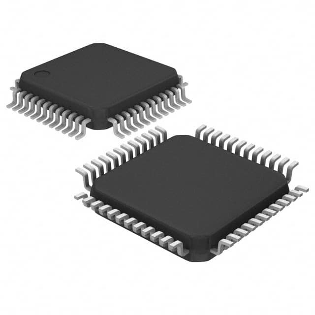
- Part No.:
- MAX2991ECM+
- Manufacturer:
- Analog Devices Inc./Maxim Integrated
- Category:
- Telecom
- Package:
- 48-LQFP
- Datasheet:
-
 MAX2991ECM+.pdf
- Description:
- IC TELECOM INTERFACE 48LQFP
- Quantity:
- Payment:

- Shipping:

Inventory:2,746
Please send an inquiry. Send us your inquiry, and we will respond immediately.
Product details
Overview
The MAX2991ECM+ from Maxim Integrated is a power-line communications (PLC) analog front-end transceiver IC designed for OFDM signal transmission over AC/DC power lines. It integrates a 10-bit DAC, 10-bit ADC, programmable band-select filters, dual-stage AGC (60dB dynamic range), and DC offset cancellation. Operating from 10kHz to 490kHz with single 3.3V supply, it supports CENELEC, FCC, and ARIB standards in smart grid metering and building automation systems.
For engineers reviewing the MAX2991ECM+ datasheet, MAX2991ECM+ pinout, MAX2991ECM+ application, or MAX2991ECM+ equivalent, this page delivers verified technical context, real-world interface timing, validated pin functions, and confirmed alternatives for PLC AFE selection in industrial and utility-grade power-line networks.
Technical Context
The MAX2991ECM+ implements a dual-path architecture: a transmit path with digital IIR filter, 10-bit DAC, lowpass filter, and programmable-gain predriver (−10dB to +6dB); and a receive path with low-noise VGA1/VGA2, configurable highpass/lowpass filters, and 10-bit ADC sampling up to 1.2Msps. Its integrated AGC adapts across 60dB input range while maintaining optimal ADC input level.
It features two independent serial interfaces: a host SPI interface (20MHz SCLK, 7-bit address + R/W + 16-bit data) for register configuration, and an AFE interface (TXCLK/RXCLK up to 19.2MHz) for high-speed data exchange with the MAX2990 baseband modem. Filter corner frequencies are programmable per standard band via internal IIR biquad coefficients.
Key Specifications
| Parameter | Value and Actual Design Meaning |
|---|---|
| Operating Frequency Band | 10kHz–490kHz; supports CENELEC A (3–95kHz), FCC/ARIB (150–490kHz), narrowband (30–140kHz), and full-band modes via programmable filters. |
| DAC/ADC Resolution & Rate | 10-bit resolution with 1.2Msps sampling; enables high-fidelity OFDM symbol reconstruction and digitization of wideband PLC signals. |
| Dynamic Range & AGC | 60dB receiver dynamic range with dual-stage automatic gain control; maintains signal integrity across varying line impedance and noise conditions. |
| Supply & Power | Single 3.3V supply; 70mA typical current in Rx mode, 36mA in Tx mode; enables low-power operation in battery-backed or energy-harvested nodes. |
| Filter Accuracy | ±3.0% cutoff accuracy for CENELEC A, ±5.0% for FCC/ARIB bands; ensures regulatory compliance without external calibration. |
| Interface Clock Speed | SPI clock up to 20MHz; AFE interface clocks (TXCLK/RXCLK) up to 19.2MHz; supports real-time streaming between AFE and baseband modem. |
| Operating Temperature | −40°C to +85°C; qualified for outdoor metering enclosures and industrial HVAC control panels. |
Pinout & Package
MAX2991ECM+ is housed in a 48-pin LQFP package (7mm × 7mm, 0.5mm pitch) with six analog ground pins (GND1–GND6), four analog supplies (VDD1–VDD6), and dedicated bias resistors (RBIASTX, RBIASRX) for precise transmitter/receiver current setting.
| Pin/Terminal | Circuit Role | Design Meaning |
|---|---|---|
| RXINP / RXINN | AC power-line differential input | Direct connection to coupling circuitry; accepts ±1.5Vp-p common-mode-rejected signals from line coupler. |
| TXOUTP / TXOUTN | AC power-line differential output | Drives external line driver; supports 1.5Vp-p swing at 50kHz into 50Ω single-ended load. |
| AGCFRZ / AGCCS | AGC control inputs | AGCFRZ freezes VGA1/VGA2 gains instantly; AGCCS initiates adaptive gain timer upon preamble detection. |
| ENTX / ENRX | Transmit/receive enable | Active-low enables; allows independent power gating of Tx or Rx paths to reduce system-level idle current. |
| TXCONV / RXCONV | Data frame synchronization | Falling-edge-triggered start signals; define boundaries of 10-bit Tx/Rx data frames aligned to TXCLK/RXCLK. |
| SCLK / SDIN / SDOUT / CS | Host SPI interface | Full-duplex 20MHz SPI for register access; supports 7-bit address + R/W bit + 16-bit data frame per transaction. |
| TXCLK / RXCLK | AFE interface clocks | 19.2MHz clocks drive synchronous 10-bit data transfer with MAX2990; timing-critical for OFDM symbol alignment. |
| RBIASRX / RBIASTX | External bias resistor terminals | Connect 25kΩ ±1% resistors to GND to set precise receive/transmit bias currents per datasheet layout guidelines. |
Key Features
| Feature | Design Value |
|---|---|
| Integrated band-select filtering | Programmable lowpass/highpass filters support CENELEC, FCC, ARIB, and custom bands without external components. |
| 60dB dynamic range AGC | Dual-stage VGA automatically scales weak and strong PLC signals to maximize ADC utilization and SNR. |
| DC offset cancellation loop | On-chip feedback loop minimizes baseline drift from coupling transformer saturation or amplifier offsets. |
| Variable predriver gain | 16dB adjustable range (−10dB to +6dB) enables precise output level tuning for different line impedances and regulatory limits. |
| Dual serial interfaces | Separate SPI (for config) and AFE (for data) interfaces prevent contention and ensure deterministic timing for real-time PLC PHY handshaking. |
Applications
| Automatic Meter Reading (AMR) | Home Automation |
|---|---|
Use Scenario: Two-way communication between electricity/water/gas meters and central collection units over existing AC wiring. IC Role / Device Role / Timing Role: AFE transceiver handling analog signal conditioning, modulation/demodulation interface, and line coupling for OFDM-based PLC PHY layer. Use Value: Enables certified CENELEC-compliant data rates up to 1.2Msps with 60dB AGC tolerance for noisy residential distribution lines. | Use Scenario: Interconnecting lighting, HVAC, security, and appliance controllers using in-wall power lines instead of dedicated wiring. IC Role / Device Role / Timing Role: Analog front-end bridging digital baseband (e.g., MAX2990) to AC mains; provides programmable band filtering for FCC/ARIB regions. Use Value: Single-chip solution eliminates discrete op-amps, filters, and gain stages-reducing BOM cost and PCB area by >40% vs. discrete AFE designs. |
| Smart Grid Infrastructure | Industrial Building Automation |
Use Scenario: Substation-to-transformer and transformer-to-meter communication for demand response, outage detection, and firmware updates. IC Role / Device Role / Timing Role: High-reliability PLC AFE operating across −40°C to +85°C with integrated DC offset cancellation for long-term stability. Use Value: 48-pin LQFP package with six isolated ground pins ensures EMI robustness in electrically noisy substations and reduces layout sensitivity to ground bounce. | Use Scenario: Centralized control of HVAC, lighting, fire alarms, and access systems in commercial buildings using legacy power infrastructure. IC Role / Device Role / Timing Role: Signal conditioner and interface between PLC baseband processor and 230VAC line; supports narrowband (30–140kHz) for reduced interference in dense environments. Use Value: Programmable filter cutoff accuracy (±3.0% for CENELEC A) guarantees compliance with EN 50065-1 without factory trimming or calibration. |
Equivalent & Alternatives
The following parts are listed as comparable options for similar PLC analog front-end applications.
| Alternative Part | Technical Difference | Application Difference | Selection Advice |
|---|---|---|---|
| ST7580 | Integrated 12-bit ADC/DAC; fixed 100kHz–500kHz band; no programmable IIR filter; requires external AGC. | Targeted at G3-PLC and PRIME standards; lacks CENELEC A sub-band optimization and DC offset loop. | Choose ST7580 only when G3-PLC compliance is mandatory and external AGC design resources are available. |
| TI TLPLC100 | 10-bit ADC/DAC; 10kHz–490kHz coverage; integrated AGC but limited to 45dB range; no dual-VGA architecture. | Optimized for TI's SYS/BIOS-based PLC stack; lacks independent ENTX/ENRX control and freeze-mode AGC. | Select TLPLC100 if using TI's CC1352R-based PLC gateway and lower AGC range suffices for controlled lab environments. |
Compared with ST7580 and TLPLC100, the MAX2991ECM+ delivers superior 60dB AGC range, on-chip DC offset cancellation, and fully programmable IIR filters-making it the only option supporting simultaneous CENELEC A, FCC, and ARIB compliance with zero external analog components.
Availability
MAX2991ECM+ is available at Aetrix Electronics and suitable for automatic meter reading, smart grid infrastructure, and industrial building automation requiring stable component supply across extended temperature ranges and global regulatory bands.
Supply support for MAX2991ECM+ includes scheduled delivery planning, volume procurement assistance, BOM continuity management, traceable sourcing, and lifecycle availability coordination for OEM customers, industrial embedded developers, connected-device designers, and electronics production programs.
Manufacturer
Maxim Integrated, now part of Analog Devices, designs precision analog, mixed-signal, and power management ICs for industrial, automotive, and communications markets.
The MAX2991ECM+ belongs to Maxim's PLC AFE product line, engineered specifically to simplify OFDM-based power-line networking by integrating all critical analog signal chain functions-including dual-path filtering, AGC, and high-speed converters-into a single 48-pin LQFP device.
FAQ
What is the primary function of the MAX2991ECM+ in a PLC system?
The MAX2991ECM+ serves as the analog front-end transceiver in OFDM-based power-line communication systems. It conditions, converts, and filters signals between the AC/DC power line and a digital baseband modem like the MAX2990. Its core functions include 10-bit DAC-driven transmit path signal shaping, 10-bit ADC-based receive path digitization, 60dB AGC adaptation, and programmable band-select filtering for CENELEC, FCC, and ARIB compliance-all integrated into a single 48-pin LQFP package.
Does the MAX2991ECM+ require external passive components for basic operation?
Yes, the MAX2991ECM+ requires external passive components for stable operation: 100nF + 10µF bypass capacitors on each VDD pin (VDD1–VDD6), 25kΩ ±1% resistors connected from RBIASTX and RBIASRX to ground for bias current setting, and external line coupling circuitry (transformer or capacitor network) between RXINP/RXINN and TXOUTP/TXOUTN and the AC power line. No external filters, op-amps, or AGC circuitry are needed due to full integration.
How does the AGC system in the MAX2991ECM+ differ from conventional approaches?
The MAX2991ECM+ implements a dual-stage, adaptive AGC with 60dB dynamic range using two variable-gain amplifiers (VGA1 and VGA2) and dedicated control signals (AGCCS and AGCFRZ). Unlike fixed-gain or single-stage AGC ICs, it continuously adapts to incoming signal amplitude while allowing freeze-mode locking during burst reception. The AGCCS signal synchronizes gain adaptation with digital PHY preamble detection, and AGCFRZ provides instantaneous gain hold-critical for multi-tone OFDM symbol integrity.
Can the MAX2991ECM+ operate independently without the MAX2990 baseband modem?
No, the MAX2991ECM+ is not a standalone modem-it is an analog front-end transceiver that must be paired with a digital baseband processor such as the MAX2990. It handles only analog signal conversion and conditioning; all OFDM modulation/demodulation, MAC layer processing, and protocol stack execution occur in the baseband device. The AFE interface (TXCLK/RXCLK/TXDATA/RXDATA) provides the high-speed data path between the two chips, and register configuration is performed via the separate host SPI interface.
What are the key timing requirements for interfacing the MAX2991ECM+ with a microcontroller via SPI?
The MAX2991ECM+ SPI interface operates up to 20MHz SCLK with strict timing: minimum tCH/tCL = 20ns, tCSS0/tCSH0 = 10ns, tDS/tDH = 10ns, and tDO1/tDO2 = 20ns/5ns. Each transaction uses a 7-bit register address, 1-bit R/W flag, and 16-bit data payload. Data is sampled on the falling edge of SCLK and driven on the rising edge. Critical registers include RXCONF (0x00) for receiver configuration and TXCONF (0x01) for transmit settings-both accessible only through this SPI interface.
MAX2991ECM+ Specifications
- Product attributes
- Attribute value
- Manufacturer:
- Analog Devices Inc./Maxim Integrated
- Series:
- -
- Package/Case:
- 48-LQFP
- Packaging:
- Tray
- Product Status:
- Active
- Function:
- Analog Front-End Transceiver
- Interface:
- SPI Serial
- Number of Circuits:
- 1
- Voltage - Supply:
- 3V ~ 3.6V
- Current - Supply:
- 36mA, 70mA
- Power (Watts):
- 1.54 W
- Operating Temperature:
- -40°C ~ 85°C
- Grade:
- -
- Qualification:
- -
- Mounting Type:
- Surface Mount
- Supplier Device Package:
- 48-LQFP (7x7)
MAX2991ECM+ FAQ
1.How can I place an order for MAX2991ECM+ through Aetrix?
Please submit a Request for Quotation (RFQ) for MAX2991ECM+ on Aetrix. Our sales agent will provide a competitive quotation and guide you through the order confirmation once you accept the terms.
2.Are the price and stock information for MAX2991ECM+ reliable?
The price and inventory of MAX2991ECM+ are updated periodically and may fluctuate due to market conditions. Stock and pricing data are typically refreshed every 24 hours. Quotation validity for MAX2991ECM+ is usually 5 days.
3.What payment methods are accepted for MAX2991ECM+?
We accept Wire Transfer, PayPal, Credit Card, Western Union, MoneyGram, and Escrow for MAX2991ECM+ transactions.
Note: Certain payment methods may incur a processing fee.
4.How is shipping managed for MAX2991ECM+?
MAX2991ECM+ orders can be shipped via leading logistics carriers, including DHL, UPS, FedEx, TNT, or Registered Mail.
Once your MAX2991ECM+ order is processed, you will receive an email with the shipment details and tracking number.
Note: Tracking information may take up to 24 hours to appear. Express delivery typically takes 3–5 business days.
5.How can I obtain technical support or documentation for MAX2991ECM+?
For technical support, including MAX2991ECM+ datasheets, pinout diagrams, or application guidance, please contact our engineering support team. They can provide detailed documentation and assistance for your MAX2991ECM+ requirements.
6.How does Aetrix verify that MAX2991ECM+ is sourced from the original manufacturer or authorized distributors?
All MAX2991ECM+ products on Aetrix are procured from qualified distributors and authorized channels. Our dedicated quality assurance team conducts strict verification, including traceability checks and, if necessary, third-party testing. This ensures that MAX2991ECM+ meets industry standards.
7.What is the process for return or replacement of MAX2991ECM+?
All MAX2991ECM+ units undergo pre-shipment inspection (PSI). If there is an issue with MAX2991ECM+, returns or replacements are accepted under the following conditions:
1.Quantity discrepancies, incorrect items, or visible external defects (such as breakage or corrosion), acknowledged by Aetrix.
2.The issue is reported within 90 days of delivery.
3.The MAX2991ECM+ part is unused and in its original packaging.
Return procedure for MAX2991ECM+:
1.Submit a request within 90 days.
2.Obtain a Return Material Authorization (RMA) from Aetrix.
MAX2991ECM+ Tags

-
LMC567CMX/NOPB
Texas Instruments
-
LM567CMX/NOPB
Texas Instruments
-
LM567CM/NOPB
Texas Instruments

-
VSC8531XMW-02
Microchip Technology
-
VSC8531XMW-05
Microchip Technology

-
GPY115C0VI
MaxLinear, Inc.

-
SI32185-A-FMR
Skyworks Solutions Inc.

-
VSC8541XMV-05
Microchip Technology

-
SI32178-B-FM1R
Skyworks Solutions Inc.
-
GPY215C0VI
MaxLinear, Inc.

-
CPC7514ZTR
Littelfuse Inc.

-
VSC8502XML-03
Microchip Technology
Tech Hub

A practical engineering guide to 3.3V and 5V logic compatibility, input thresholds, resistor dividers, translator ICs, MOSFET level shifting, I2C pull-ups, timing limits and power-sequencing risks.

The 74HC595 uses push-pull logic outputs, while the TPIC6B595 uses 50 V open-drain DMOS sinks for higher-power loads. This guide compares timing, current limits, 3.3 V interfacing, load wiring, thermal…

The 74HC595 converts serial data into eight stable parallel outputs. This guide covers pin functions, shift and storage timing, OE and MR behavior, drive-current limits, cascading, voltage compatibilit…

A technical comparison of level-sensitive latches and edge-triggered flip-flops, covering timing windows, setup and hold limits, master–slave operation, time borrowing, race-through, HDL inference and…

A D latch stores one bit while Enable controls when data can pass. This reference covers gate-level operation, truth tables, transparency, setup and hold timing, LE versus OE, common ICs and practical …

An SR latch stores one bit through cross-coupled feedback. This engineering reference covers NOR and NAND implementations, truth tables, forbidden-state recovery, gated operation, switch debouncing, fa…

Latch circuits retain one bit through feedback. This technical reference covers SR and D latches, truth tables, transparency, timing limits, latch-versus-flip-flop behavior, applications and common log…

An engineering guide to LED driver operation, constant-current and constant-voltage outputs, linear and switching topologies, dimming, IC selection, calculations, replacement compatibility, and fault c…

Operational amplifier guide covering op amp basics, feedback, ideal vs real op amps, common configurations, buffer circuits, offset, bias current, gain-bandwidth, slew rate, rail-to-rail limits and sel…

Jumper cables guide covering safe connection order, red and black clamp placement, final ground connection, cable gauge, length, clamp quality, copper vs CCA cables, jump starter comparison and battery…


