
 My Inquiry
 My Account


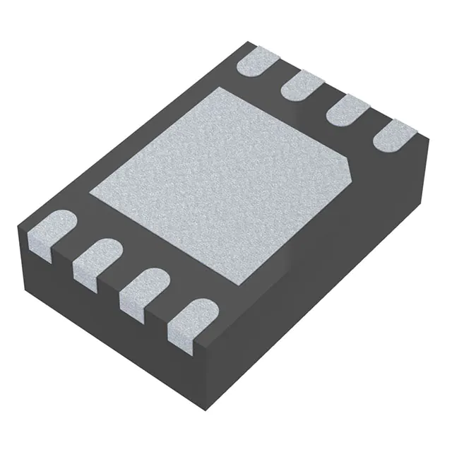
Analog Devices Inc./Maxim Integrated MAX31740ATA+
- Part No.:
- MAX31740ATA+
- Manufacturer:
- Analog Devices Inc./Maxim Integrated
- Category:
- Specialized
- Package:
- 8-WFDFN Exposed Pad
- Datasheet:
-
 MAX31740ATA+.pdf
- Description:
- IC INTERFACE SPECIALIZED 8TDFN
- Quantity:
- Payment:

- Shipping:

Inventory:4,089
Please send an inquiry. Send us your inquiry, and we will respond immediately.
Product details
Overview
MAX31740ATA+ from Maxim Integrated is an ultra-simple, self-contained PWM fan-speed controller IC that monitors external NTC thermistor temperature and generates a programmable PWM output to regulate 2-, 3-, or 4-wire fans without microcontroller firmware. It operates from 3.0V to 5.5V, supports -40°C to +125°C ambient, delivers 500–1100µA supply current, and uses external resistors/capacitors to set TSTART, DMIN, slope, and PWM frequency (e.g., 33Hz or 25kHz). It is used in thermal management for computing and industrial equipment.
For engineers reviewing the MAX31740ATA+ datasheet, MAX31740ATA+ pinout, MAX31740ATA+ application, or MAX31740ATA+ equivalent, this page provides verified technical context, hardwired configuration logic, thermal control transfer function details, package-validated thermal resistance (θJA = 60°C/W), and AEC-Q100-qualified alternatives for automotive-grade thermal subsystems.
Technical Context
The MAX31740ATA+ implements analog closed-loop fan control using an internal sawtooth oscillator (frequency set by CF on FREQ pin), a precision amplifier with gain set by RSLOPE and internal 22kΩ RFBK, and a thermistor-based voltage divider at SENSE to generate a positive temperature coefficient signal. Its duty-cycle vs. temperature profile is fully defined by passive component selection-not digital registers.
It features a CMOS PWM_OUT driver (VOH = VDD – 0.4V, VOL = 0.4V @ ±6mA), internal 60kΩ D0 pulldown, 19nA SENSE input bias, and ±12mV sawtooth offset referenced to VDD/2. The device achieves linear thermal response via resistor-ratio scaling of thermistor nonlinearity, with no software or calibration required.
Key Specifications
| Parameter | Value and Actual Design Meaning |
|---|---|
| Supply Voltage | 3.0V to 5.5V - Enables direct interface with common logic rails and avoids LDO dependency. |
| PWM Frequency Range | 10.5455×10⁻⁶ / CF Hz - Configurable from ~33Hz (2-wire power modulation) to 25kHz (4-wire speed control) via single capacitor. |
| Operating Temperature | -40°C to +125°C - Validated for under-hood automotive and industrial edge environments. |
| Supply Current | 500–1100µA - Ultra-low quiescent draw enables always-on thermal monitoring in power-constrained systems. |
| SENSE Input Bias | 19nA - Minimizes thermistor-divider error and preserves accuracy across full temperature range. |
| Thermal Resistance θJA | 60°C/W - Confirmed for 2mm × 3mm TDFN-EP on 4-layer JEDEC board; enables compact heatsink-free layout. |
| PWM Output Drive | VOL = 0.4V @ 6mA sink / VOH = VDD – 0.4V @ 6mA source - Directly drives standard fan PWM inputs without level-shifting. |
Pinout & Package
MAX31740ATA+ is housed in a 2mm × 3mm, 8-pin TDFN-EP package with exposed pad (EP) tied to GND. Thermal performance is optimized for surface-mount PCBs with proper copper pour under EP.
| Pin/Terminal | Circuit Role | Design Meaning |
|---|---|---|
| 1 - DMIN | Minimum duty cycle reference input | Voltage divider sets DMIN between 0.05VDD and 0.2VDD; defines lowest active fan speed point. |
| 2 - SLOPE | Temperature-to-duty-cycle gain control | External resistor sets amplifier gain (AV = 1 + RFBK/RSLOPE); determines °C-per-% duty cycle slope. |
| 3 - SENSE | NTC thermistor voltage sensing node | Accepts negative-TC voltage divider output; 19nA bias ensures minimal loading error. |
| 4 - GND | Power and signal reference ground | Primary return path; EP must also connect to GND but not serve as sole ground connection. |
| 5 - FREQ | PWM oscillator timing input | Capacitor CF sets frequency per f = 10.5455×10⁻⁶/CF; max 10pF total capacitance allowed. |
| 6 - D0 | Low-temperature duty cycle selector | Logic level (GND = 0%, VDD = DMIN) selects fan behavior below TMIN; internal 60kΩ pulldown. |
| 7 - PWM_OUT | CMOS fan speed control output | Directly interfaces 4-wire fan PWM inputs or 2/3-wire fan power transistors; rail-to-rail swing. |
| 8 - VDD | Power supply input | 3.0–5.5V operation; requires ≥0.01µF ceramic bypass capacitor placed adjacent to pin. |
Key Features
| Feature | Design Value |
|---|---|
| Self-contained PWM generation | Eliminates MCU, firmware, and associated BOM cost-fan control implemented with 4–6 passive components. |
| Linear temperature-duty-cycle transfer | Smooth, audibly quiet fan ramping achieved via analog slope control-no stepwise digital transitions. |
| AEC-Q100 qualified | Validated for automotive under-hood applications including engine control units and ADAS cooling modules. |
| Configurable start temperature (TSTART) | Set by matching RST to thermistor resistance at desired TSTART-enables precise thermal activation thresholds. |
| Wide supply voltage range | 3.0V–5.5V operation supports both 3.3V and 5V system rails without external regulators. |
Applications
| Server CPU Cooling | Automotive ADAS Module Cooling |
|---|---|
Use Scenario: Regulating airflow over high-power CPUs in 1U rack servers where acoustic noise and thermal headroom are tightly constrained. IC Role / Device Role / Timing Role: Analog fan-speed controller generating variable-frequency PWM based on NTC thermistor feedback from heatsink baseplate. Use Value: Reduces audible fan whine by enabling smooth 33Hz–25kHz PWM transitions and eliminates firmware development cycles for thermal loop tuning. |
Use Scenario: Managing heat dissipation in radar processing units mounted near vehicle engines, subject to rapid ambient shifts and vibration. IC Role / Device Role / Timing Role: AEC-Q100-compliant thermal supervisor driving 4-wire fans via 25kHz PWM while operating across -40°C to +125°C. Use Value: Ensures reliable fan startup and continuous speed modulation without MCU intervention-even during cold cranking or thermal shock events. |
| Industrial PLC Enclosure Ventilation | 5G Baseband Unit Thermal Management |
Use Scenario: Maintaining safe operating temperatures inside sealed industrial PLC cabinets exposed to factory-floor ambient swings from 0°C to 70°C. IC Role / Device Role / Timing Role: Standalone fan controller interfacing with chassis-mounted NTC and driving 2-wire fans via low-frequency PWM power modulation. Use Value: Achieves >15-year field reliability with zero firmware updates and immunity to EMI-induced digital reset faults. |
Use Scenario: Dynamic cooling of FPGA and RF front-end ICs in outdoor 5G macro base stations requiring silent, responsive thermal regulation. IC Role / Device Role / Timing Role: High-accuracy analog controller setting TSTART at 45°C and full-speed onset at 75°C using Murata NCP15XW153J03RC thermistor. Use Value: Delivers <±2°C thermal setpoint accuracy across life cycle without calibration drift or software recalibration. |
Equivalent & Alternatives
The following parts are listed as comparable options for similar fan-speed control applications.
| Alternative Part | Technical Difference | Application Difference | Selection Advice |
|---|---|---|---|
| MAX31723ATB+ | Digital I²C temperature sensor only-no integrated PWM generator or fan drive capability. | Requires external MCU and PWM driver circuitry; adds latency and firmware overhead. | Select when precise digital temperature readout is primary need and fan control is handled elsewhere. |
| LM7322MFX/NOPB | Rail-to-rail op amp-no built-in oscillator, thermistor interface, or PWM logic; requires full discrete design. | Not a drop-in solution; demands custom analog design for slope, TSTART, and duty-cycle generation. | Select only for highly customized thermal control where MAX31740ATA+ configurability is insufficient. |
Compared with MAX31740ATA+, MAX31723ATB+ provides higher-resolution temperature data but no fan actuation, while LM7322MFX/NOPB offers flexibility at the cost of 3× board area and 6-month firmware development-making MAX31740ATA+ optimal for time-to-market-critical thermal subsystems.
Availability
MAX31740ATA+ is available at Aetrix Electronics and suitable for server CPU cooling, automotive ADAS module cooling, and industrial PLC enclosure ventilation requiring stable component supply, long-term lifecycle support, and AEC-Q100 compliance.
Supply support for MAX31740ATA+ includes scheduled delivery planning, volume procurement assistance, BOM continuity management, traceable sourcing, and lifecycle availability coordination for OEM customers, industrial embedded developers, connected-device designers, and electronics production programs.
Manufacturer
Maxim Integrated, now part of Analog Devices, designs precision analog and mixed-signal ICs for demanding industrial, automotive, and communications applications.
The MAX31740ATA+ belongs to Maxim's thermal management product line, engineered specifically to replace microcontroller-based fan control with deterministic, low-power, analog-configurable solutions for harsh-environment electronics.
FAQ
What is the maximum allowable capacitance on the FREQ pin of the MAX31740ATA+?
The MAX31740ATA+ datasheet specifies a maximum external capacitance of 10pF on the FREQ pin (including PCB trace and parasitic contributions) to ensure stable oscillator operation and accurate PWM frequency. Exceeding this limit may cause frequency drift or startup failure. For a target 25kHz PWM, use 430pF CF; for 33Hz, use 330nF CF-both well within the 10pF total load constraint when properly routed.
How does the MAX31740ATA+ achieve AEC-Q100 qualification?
The MAX31740ATA+ achieves AEC-Q100 qualification through rigorous stress testing across temperature, voltage, and lifetime parameters-including HTOL (high-temperature operating life), TC (temperature cycling), and AC/DC electrical characterization at -40°C to +125°C. This validation confirms its suitability for automotive under-hood applications such as ADAS cooling modules, where reliability under thermal shock and extended operation is mandatory.
Can the MAX31740ATA+ control a 2-wire fan without additional components?
Yes-the MAX31740ATA+ can directly control a 2-wire fan using low-frequency PWM (e.g., 33Hz) applied to the fan's power supply via an external MOSFET or bipolar transistor, as shown in the 2-Wire Fan-Speed Controller typical application circuit. No additional ICs are needed, though fan compatibility with power-supply modulation must be verified per manufacturer specifications to avoid audible noise or premature wear.
What is the role of the exposed pad (EP) on the MAX31740ATA+ TDFN package?
The exposed pad (EP) on the MAX31740ATA+ serves as a thermal and electrical connection to GND, reducing junction-to-ambient thermal resistance to 60°C/W. It must be soldered to a PCB copper pour tied to GND-but cannot be the sole ground connection; the dedicated GND pin (Pin 4) remains essential for signal integrity and current return paths. Leaving EP unconnected degrades thermal performance and risks overheating.
How is the starting temperature (TSTART) configured on the MAX31740ATA+?
TSTART on the MAX31740ATA+ is set by selecting RST to match the resistance of the external NTC thermistor at the desired TSTART temperature-for example, if TSTART = 45°C and the thermistor reads 12.3kΩ at that point, RST = 12.3kΩ. This resistor forms half of the SENSE voltage divider, establishing the temperature threshold at which PWM duty cycle begins rising from DMIN.
MAX31740ATA+ Specifications
- Product attributes
- Attribute value
- Manufacturer:
- Analog Devices Inc./Maxim Integrated
- Series:
- -
- Package/Case:
- 8-WFDFN Exposed Pad
- Packaging:
- Strip
- Product Status:
- Active
- Applications:
- Fan Controller
- Interface:
- -
- Voltage - Supply:
- 3V ~ 5.5V
- Supplier Device Package:
- 8-TDFN (2x3)
- Grade:
- -
- Qualification:
- -
- Mounting Type:
- Surface Mount
MAX31740ATA+ FAQ
1.How can I place an order for MAX31740ATA+ through Aetrix?
Please submit a Request for Quotation (RFQ) for MAX31740ATA+ on Aetrix. Our sales agent will provide a competitive quotation and guide you through the order confirmation once you accept the terms.
2.Are the price and stock information for MAX31740ATA+ reliable?
The price and inventory of MAX31740ATA+ are updated periodically and may fluctuate due to market conditions. Stock and pricing data are typically refreshed every 24 hours. Quotation validity for MAX31740ATA+ is usually 5 days.
3.What payment methods are accepted for MAX31740ATA+?
We accept Wire Transfer, PayPal, Credit Card, Western Union, MoneyGram, and Escrow for MAX31740ATA+ transactions.
Note: Certain payment methods may incur a processing fee.
4.How is shipping managed for MAX31740ATA+?
MAX31740ATA+ orders can be shipped via leading logistics carriers, including DHL, UPS, FedEx, TNT, or Registered Mail.
Once your MAX31740ATA+ order is processed, you will receive an email with the shipment details and tracking number.
Note: Tracking information may take up to 24 hours to appear. Express delivery typically takes 3–5 business days.
5.How can I obtain technical support or documentation for MAX31740ATA+?
For technical support, including MAX31740ATA+ datasheets, pinout diagrams, or application guidance, please contact our engineering support team. They can provide detailed documentation and assistance for your MAX31740ATA+ requirements.
6.How does Aetrix verify that MAX31740ATA+ is sourced from the original manufacturer or authorized distributors?
All MAX31740ATA+ products on Aetrix are procured from qualified distributors and authorized channels. Our dedicated quality assurance team conducts strict verification, including traceability checks and, if necessary, third-party testing. This ensures that MAX31740ATA+ meets industry standards.
7.What is the process for return or replacement of MAX31740ATA+?
All MAX31740ATA+ units undergo pre-shipment inspection (PSI). If there is an issue with MAX31740ATA+, returns or replacements are accepted under the following conditions:
1.Quantity discrepancies, incorrect items, or visible external defects (such as breakage or corrosion), acknowledged by Aetrix.
2.The issue is reported within 90 days of delivery.
3.The MAX31740ATA+ part is unused and in its original packaging.
Return procedure for MAX31740ATA+:
1.Submit a request within 90 days.
2.Obtain a Return Material Authorization (RMA) from Aetrix.
MAX31740ATA+ Tags

-
NVT4857UKAZ
NXP Semiconductors

-
TCA8418RTWR
Texas Instruments

-
PCA9546APWR
Texas Instruments

-
MD0100N8-G
Microchip Technology

-
PCA9548APW,118
NXP Semiconductors

-
PCA9540BDP,118
NXP Semiconductors

-
PCA9548APWR
Texas Instruments

-
PCA9546APW,118
NXP Semiconductors

-
PTN3360DBS,518
NXP Semiconductors

-
PCA9546ABS,118
NXP Semiconductors

-
PCA9518PWR
Texas Instruments

-
PCA9545APW,118
NXP Semiconductors
Tech Hub

A practical engineering guide to 3.3V and 5V logic compatibility, input thresholds, resistor dividers, translator ICs, MOSFET level shifting, I2C pull-ups, timing limits and power-sequencing risks.

The 74HC595 uses push-pull logic outputs, while the TPIC6B595 uses 50 V open-drain DMOS sinks for higher-power loads. This guide compares timing, current limits, 3.3 V interfacing, load wiring, thermal…

The 74HC595 converts serial data into eight stable parallel outputs. This guide covers pin functions, shift and storage timing, OE and MR behavior, drive-current limits, cascading, voltage compatibilit…

A technical comparison of level-sensitive latches and edge-triggered flip-flops, covering timing windows, setup and hold limits, master–slave operation, time borrowing, race-through, HDL inference and…

A D latch stores one bit while Enable controls when data can pass. This reference covers gate-level operation, truth tables, transparency, setup and hold timing, LE versus OE, common ICs and practical …

An SR latch stores one bit through cross-coupled feedback. This engineering reference covers NOR and NAND implementations, truth tables, forbidden-state recovery, gated operation, switch debouncing, fa…

Latch circuits retain one bit through feedback. This technical reference covers SR and D latches, truth tables, transparency, timing limits, latch-versus-flip-flop behavior, applications and common log…

An engineering guide to LED driver operation, constant-current and constant-voltage outputs, linear and switching topologies, dimming, IC selection, calculations, replacement compatibility, and fault c…

Operational amplifier guide covering op amp basics, feedback, ideal vs real op amps, common configurations, buffer circuits, offset, bias current, gain-bandwidth, slew rate, rail-to-rail limits and sel…

Jumper cables guide covering safe connection order, red and black clamp placement, final ground connection, cable gauge, length, clamp quality, copper vs CCA cables, jump starter comparison and battery…


