
 My Inquiry
 My Account


Analog Devices Inc./Maxim Integrated MAX31851RATB+T
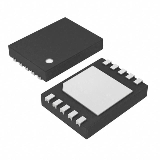
- Part No.:
- MAX31851RATB+T
- Manufacturer:
- Analog Devices Inc./Maxim Integrated
- Category:
- Sensor and Detector Interfaces
- Package:
- 10-WFDFN Exposed Pad
- Datasheet:
-
 MAX31851RATB+T.pdf
- Description:
- IC THRMOCPLE TO DIG CONV 10TDFN
- Quantity:
- Payment:

- Shipping:

Inventory:2,909
Please send an inquiry. Send us your inquiry, and we will respond immediately.
Product details
Overview
MAX31851RATB+T from Maxim Integrated is a cold-junction compensated, 1-Wire thermocouple-to-digital converter optimized for R-type thermocouples. It delivers 14-bit resolution (0.25°C), supports thermocouple temperature range from –50°C to +1768°C, achieves ±7°C total error over full operating range (–40°C to +125°C), and integrates fault detection for open/shorted thermocouple leads. It is used in high-temperature industrial furnace monitoring where single-wire digital interface and parasitic power simplify sensor node deployment.
For engineers reviewing the MAX31851RATB+T datasheet, MAX31851RATB+T pinout, MAX31851RATB+T application, or MAX31851RATB+T equivalent, key selection considerations include R-type thermocouple support, 1-Wire read-only interface timing compliance, cold-junction compensation accuracy at elevated ambient temperatures, and AD0–AD3 address pin mapping for multi-node bus configuration.
Technical Context
The MAX31851RATB+T implements a dedicated analog front-end with programmable gain and offset correction tailored to R-type thermocouple sensitivity (10.506 µV/°C), coupled with a 14-bit sigma-delta ADC and integrated die temperature sensor for cold-junction compensation. Its internal switch matrix isolates thermocouple inputs during cold-junction measurement and fault detection phases.
It operates in either local VDD-powered mode or parasite-power mode via DQ, requiring external strong pullup during conversion (tCONV = 72–100 ms). The device uses a fixed 64-bit ROM with family code 0x3B and reports location address bits AD3–AD0 in Scratchpad Byte 4, enabling deterministic node identification on shared 1-Wire buses.
Key Specifications
| Parameter | Value and Actual Design Meaning |
|---|---|
| Thermocouple Type | R-type only - calibrated for 10.506 µV/°C nominal sensitivity and extended range up to +1768°C |
| Temperature Resolution | 0.25°C - 14-bit output format enables precise incremental thermal trending |
| Cold-Junction Error | ±2°C (–40°C to +100°C) - ensures accurate ambient reference compensation across industrial operating range |
| Conversion Time | 72–100 ms - fixed duration covering thermocouple, cold-junction, and fault detection cycles |
| Supply Mode | VDD-powered or parasite-powered - eliminates need for local regulator when bus topology permits |
| Interface Protocol | 1-Wire read-only - single data line + ground; requires master-initiated commands (e.g., Convert T [0x44]) |
| Fault Detection | Open thermocouple, short-to-GND, short-to-VDD - status reported in Scratchpad Bytes 2–3 bit fields |
Pinout & Package
TDFN-EP (3mm × 4mm, 10-pin, exposed pad); RoHS-compliant; moisture sensitivity level MSL-1.
| Pin/Terminal | Circuit Role | Design Meaning |
|---|---|---|
| GND (Pin 1) | Ground reference | Primary return path for analog and digital circuitry; must be low-impedance connection to system ground plane |
| T– (Pin 2) | Thermocouple negative input | Connects to platinum/rhodium leg of R-type thermocouple; internally biased to avoid floating input errors |
| T+ (Pin 3) | Thermocouple positive input | Connects to platinum leg of R-type thermocouple; differential input pair rejects common-mode noise |
| VDD (Pin 4) | Power supply input | Required for local power mode; must be connected to GND in parasite-power mode |
| DQ (Pin 5) | 1-Wire bidirectional I/O | Open-drain interface pin; provides data communication and parasitic power charging path via CPP capacitor |
| AD0–AD3 (Pins 6–9) | Location address inputs | Hardwired LSB–MSB address bits; define unique node ID within 16-device group on same bus |
| DNC (Pin 10) | Do Not Connect | No internal connection; must remain unconnected or tied to GND per layout guidelines |
| EP (Exposed Pad) | Thermal pad | Not electrically connected; improves thermal dissipation when soldered to ground plane |
Key Features
| Feature | Design Value |
|---|---|
| R-type thermocouple calibration | Factory-trimmed for 10.506 µV/°C sensitivity and ±7°C full-range error (–40°C to +125°C ambient) |
| Integrated cold-junction compensation | Dedicated die temperature sensor with ±2°C accuracy enables automatic offset correction without external components |
| 1-Wire multinode capability | Unique 64-bit ROM (family code 0x3B) allows >1000 devices on single bus; AD0–AD3 enable logical grouping |
| Thermocouple fault detection | Real-time open-circuit, short-to-GND, and short-to-VDD detection reported in scratchpad fault bits |
| Parasite-power operation | Eliminates local power rail; powered via DQ line using internal CPP capacitor and external strong pullup during conversion |
Applications
| Industrial Furnace Monitoring | HVAC High-Temperature Duct Sensing |
|---|---|
Use Scenario: Continuous temperature measurement inside ceramic kilns and metal heat-treatment furnaces operating above 1000°C. IC Role / Device Role / Timing Role: Primary thermocouple digitizer interfacing directly to R-type sensor; performs cold-junction compensation and fault-checked conversion every 100 ms. Use Value: Enables reliable digital readout without analog signal conditioning or separate reference junction hardware, reducing BOM count and calibration complexity. |
Use Scenario: Distributed temperature sensing across large commercial HVAC ductwork with centralized microcontroller polling. IC Role / Device Role / Timing Role: Node-level sensor endpoint on 1-Wire bus; leverages AD0–AD3 addressing to map physical duct zones without unique firmware per unit. Use Value: Simplifies wiring infrastructure by replacing multiple analog wires with single 1-Wire daisy chain, lowering installation cost and improving EMI immunity. |
| Medical Sterilization Autoclave | Power Generation Boiler Monitoring |
Use Scenario: Validated temperature logging during steam sterilization cycles requiring traceable ±1°C accuracy at 134°C. IC Role / Device Role / Timing Role: Cold-junction compensated R-type interface with fault flagging to detect thermocouple degradation before cycle failure. Use Value: Provides fail-safe indication of open/short faults prior to critical process step, supporting ISO 13485 compliance requirements. |
Use Scenario: Long-term boiler tube wall temperature monitoring in coal- and gas-fired power plants. IC Role / Device Role / Timing Role: R-type digitizer mounted near boiler header; operates in local VDD mode for stable performance at sustained +125°C ambient. Use Value: Delivers drift-stable readings over years of operation due to low long-term thermocouple drift (±0.24°C at +400°C hot junction). |
Equivalent & Alternatives
The following parts are listed as comparable options for similar thermocouple digitizer applications.
| Alternative Part | Technical Difference | Application Difference | Selection Advice |
|---|---|---|---|
| MAX31851SATB+T | Optimized for S-type thermocouples (9.587 µV/°C); identical package, pinout, and 1-Wire protocol | Suitable for lower-cost S-type sensors in lab-grade instrumentation; not interchangeable with R-type calibration | Select only if S-type thermocouple is specified; no PCB change required but firmware must match sensor type |
| AD8495ARZ | Analog output cold-junction compensated amplifier (mV/°C); requires external ADC and microcontroller interface | Used where analog integration or PWM control loops dominate; lacks built-in fault detection and 1-Wire bus capability | Choose when system already includes high-resolution ADC and needs analog feedback; adds component count and layout complexity |
Compared with MAX31851SATB+T, the MAX31851RATB+T offers higher full-scale range (+1768°C vs. +1768°C) but tighter R-type gain matching, while AD8495ARZ shifts responsibility for digitization and bus management to the host system-increasing design effort but offering greater signal-chain flexibility.
Availability
MAX31851RATB+T is available at Aetrix Electronics and suitable for industrial furnace monitoring, HVAC duct sensing, medical autoclave validation, and power generation boiler monitoring requiring stable component supply and long-term calibration integrity.
Supply support for MAX31851RATB+T includes scheduled delivery planning, volume procurement assistance, BOM continuity management, traceable sourcing, and lifecycle availability coordination for OEM customers, industrial embedded developers, connected-device designers, and electronics production programs.
Manufacturer
Maxim Integrated (now part of Analog Devices) designs precision analog and mixed-signal ICs for industrial, medical, and communications systems, with emphasis on signal integrity and low-power operation.
The MAX31850/MAX31851 product line targets distributed temperature sensing applications requiring direct thermocouple digitization, cold-junction compensation, and minimal wiring-enabling robust, scalable sensor networks in harsh environments.
FAQ
What thermocouple types does the MAX31851RATB+T support?
The MAX31851RATB+T is factory-calibrated exclusively for R-type thermocouples, with nominal sensitivity of 10.506 µV/°C and guaranteed performance from –50°C to +1768°C. It does not support K-, J-, N-, T-, S-, or E-type thermocouples-those require corresponding MAX31850/51 variants (e.g., MAX31851SATB+T for S-type). Using an R-type thermocouple with the MAX31851RATB+T ensures optimal accuracy and avoids gain/offset errors inherent in cross-type operation.
How does the MAX31851RATB+T handle cold-junction compensation?
The MAX31851RATB+T integrates a precision die temperature sensor that measures its own junction temperature, then applies algorithmic correction to the R-type thermocouple voltage using the known 10.506 µV/°C slope. This yields cold-junction-compensated temperature values stored in Scratchpad Bytes 0–1, with ±2°C error over –40°C to +100°C ambient. No external reference sensor or compensation circuitry is needed-the MAX31851RATB+T performs full compensation autonomously.
Can the MAX31851RATB+T operate without a local power supply?
Yes, the MAX31851RATB+T supports parasite-power mode via the DQ pin, eliminating the need for a local VDD supply. In this mode, VDD must be grounded, and a strong external pullup (e.g., MOSFET-switched rail) is required during temperature conversions (72–100 ms) to deliver up to 1.5 mA. Parasite power is validated up to +100°C ambient; for sustained operation above that, local VDD powering is recommended to maintain communication reliability.
What fault conditions does the MAX31851RATB+T detect?
The MAX31851RATB+T detects three thermocouple faults: open circuit (bit 0 high in Scratchpad Byte 2), short to GND (bit 1 high), and short to VDD (bit 2 high). These flags appear alongside internal cold-junction temperature data in Bytes 2–3. A fault condition also sets bit 0 of the compensated thermocouple temperature (Byte 0, MSb) to indicate invalid reading-enabling immediate host-level error handling without post-processing.
How are the AD0–AD3 pins used in the MAX31851RATB+T?
The AD0–AD3 pins (Pins 6–9) are hardwired address inputs that define a 4-bit location code for the MAX31851RATB+T on a shared 1-Wire bus. Their logic states (0 = GND, 1 = DQ or pullup) are latched at power-up and reported in Bits [3:0] of Scratchpad Byte 4. This allows up to 16 uniquely addressable MAX31851RATB+T units per bus segment, simplifying zone-based sensor mapping without requiring individual ROM searches.
MAX31851RATB+T Specifications
- Product attributes
- Attribute value
- Manufacturer:
- Analog Devices Inc./Maxim Integrated
- Package/Case:
- 10-WFDFN Exposed Pad
- Series:
- -
- Packaging:
- Tape & Reel (TR)
- Product Status:
- Obsolete
- Programmable:
- Not Verified
- Type:
- Thermocouple to Digital Converter
- Input Type:
- Thermocouple (Multiple)
- Output Type:
- Digital
- Current - Supply:
- 900 µA
- Operating Temperature:
- -40°C ~ 125°C
- Grade:
- -
- Qualification:
- -
- Mounting Type:
- Surface Mount
- Supplier Device Package:
- 10-TDFN (3x4)
MAX31851RATB+T FAQ
1.How can I place an order for MAX31851RATB+T through Aetrix?
Please submit a Request for Quotation (RFQ) for MAX31851RATB+T on Aetrix. Our sales agent will provide a competitive quotation and guide you through the order confirmation once you accept the terms.
2.Are the price and stock information for MAX31851RATB+T reliable?
The price and inventory of MAX31851RATB+T are updated periodically and may fluctuate due to market conditions. Stock and pricing data are typically refreshed every 24 hours. Quotation validity for MAX31851RATB+T is usually 5 days.
3.What payment methods are accepted for MAX31851RATB+T?
We accept Wire Transfer, PayPal, Credit Card, Western Union, MoneyGram, and Escrow for MAX31851RATB+T transactions.
Note: Certain payment methods may incur a processing fee.
4.How is shipping managed for MAX31851RATB+T?
MAX31851RATB+T orders can be shipped via leading logistics carriers, including DHL, UPS, FedEx, TNT, or Registered Mail.
Once your MAX31851RATB+T order is processed, you will receive an email with the shipment details and tracking number.
Note: Tracking information may take up to 24 hours to appear. Express delivery typically takes 3–5 business days.
5.How can I obtain technical support or documentation for MAX31851RATB+T?
For technical support, including MAX31851RATB+T datasheets, pinout diagrams, or application guidance, please contact our engineering support team. They can provide detailed documentation and assistance for your MAX31851RATB+T requirements.
6.How does Aetrix verify that MAX31851RATB+T is sourced from the original manufacturer or authorized distributors?
All MAX31851RATB+T products on Aetrix are procured from qualified distributors and authorized channels. Our dedicated quality assurance team conducts strict verification, including traceability checks and, if necessary, third-party testing. This ensures that MAX31851RATB+T meets industry standards.
7.What is the process for return or replacement of MAX31851RATB+T?
All MAX31851RATB+T units undergo pre-shipment inspection (PSI). If there is an issue with MAX31851RATB+T, returns or replacements are accepted under the following conditions:
1.Quantity discrepancies, incorrect items, or visible external defects (such as breakage or corrosion), acknowledged by Aetrix.
2.The issue is reported within 90 days of delivery.
3.The MAX31851RATB+T part is unused and in its original packaging.
Return procedure for MAX31851RATB+T:
1.Submit a request within 90 days.
2.Obtain a Return Material Authorization (RMA) from Aetrix.
MAX31851RATB+T Tags

-
RE46C100S8TF
Microchip Technology

-
XTR111AIDRCR
Texas Instruments

-
XTR111AIDGQR
Texas Instruments

-
XTR117AIDGKR
Texas Instruments
-
XTR111AIDGQT
Texas Instruments

-
XTR115UA/2K5
Texas Instruments

-
MAX14626ETT+T
Analog Devices Inc./Maxim Integrated
-
XTR116UA/2K5
Texas Instruments
-
XTR115U/2K5
Texas Instruments
-
XTR116U/2K5
Texas Instruments

-
PGA308AIDGSR
Texas Instruments

-
XTR300AIRGWR
Texas Instruments
Tech Hub

A practical engineering guide to 3.3V and 5V logic compatibility, input thresholds, resistor dividers, translator ICs, MOSFET level shifting, I2C pull-ups, timing limits and power-sequencing risks.

The 74HC595 uses push-pull logic outputs, while the TPIC6B595 uses 50 V open-drain DMOS sinks for higher-power loads. This guide compares timing, current limits, 3.3 V interfacing, load wiring, thermal…

The 74HC595 converts serial data into eight stable parallel outputs. This guide covers pin functions, shift and storage timing, OE and MR behavior, drive-current limits, cascading, voltage compatibilit…

A technical comparison of level-sensitive latches and edge-triggered flip-flops, covering timing windows, setup and hold limits, master–slave operation, time borrowing, race-through, HDL inference and…

A D latch stores one bit while Enable controls when data can pass. This reference covers gate-level operation, truth tables, transparency, setup and hold timing, LE versus OE, common ICs and practical …

An SR latch stores one bit through cross-coupled feedback. This engineering reference covers NOR and NAND implementations, truth tables, forbidden-state recovery, gated operation, switch debouncing, fa…

Latch circuits retain one bit through feedback. This technical reference covers SR and D latches, truth tables, transparency, timing limits, latch-versus-flip-flop behavior, applications and common log…

An engineering guide to LED driver operation, constant-current and constant-voltage outputs, linear and switching topologies, dimming, IC selection, calculations, replacement compatibility, and fault c…

Operational amplifier guide covering op amp basics, feedback, ideal vs real op amps, common configurations, buffer circuits, offset, bias current, gain-bandwidth, slew rate, rail-to-rail limits and sel…

Jumper cables guide covering safe connection order, red and black clamp placement, final ground connection, cable gauge, length, clamp quality, copper vs CCA cables, jump starter comparison and battery…


