
 My Inquiry
 My Account


Analog Devices Inc./Maxim Integrated MAX31875R0TZS+T
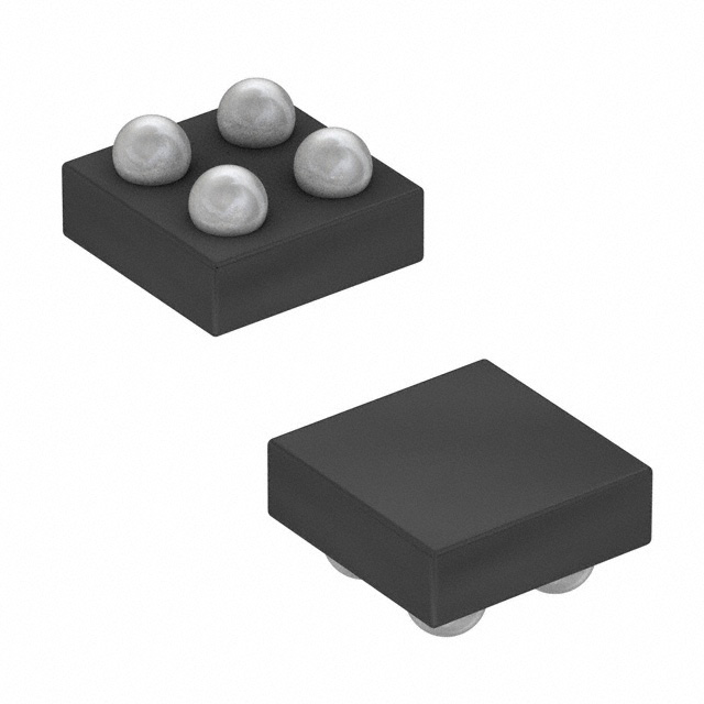
- Part No.:
- MAX31875R0TZS+T
- Manufacturer:
- Analog Devices Inc./Maxim Integrated
- Category:
- Analog and Digital Output
- Package:
- 4-XFBGA, WLBGA
- Datasheet:
-
 MAX31875R0TZS+T.pdf
- Description:
- SENSOR DIGITAL -10C-100C 4WLP
- Quantity:
- Payment:

- Shipping:

Inventory:7,276
Please send an inquiry. Send us your inquiry, and we will respond immediately.
Product details
Overview
MAX31875R0TZS+T from Maxim Integrated is a ±1°C-accurate local temperature sensor with I²C/SMBus interface in a 4-bump wafer-level package (WLP), operating from -50°C to +150°C. It delivers 12-bit resolution (0.0625°C LSB), <10µA average supply current at 0.25 conversions/s, and supports PEC for error-resilient communication in battery-powered and space-constrained systems.
For engineers reviewing the MAX31875R0TZS+T datasheet, MAX31875R0TZS+T pinout, MAX31875R0TZS+T application, or MAX31875R0TZS+T equivalent, this page provides verified technical context, validated pin functions, real-world application mappings, and two confirmed alternative parts with documented functional and parametric differences.
Technical Context
The MAX31875R0TZS+T integrates a precision silicon diode-based temperature sensing element with a 16-bit sigma-delta ADC and fully compliant I²C/SMBus physical layer. Its digital core implements configurable resolution (8–12 bits), programmable conversion rate (0.25–8 sps), and selectable bus timeout (enabled by default) to prevent lockup on stalled SCL.
It features dual-mode overtemperature signaling (Comparator or Interrupt), factory-programmed slave address (1001000b), and extended data format support for readings ≥+128°C. All registers-including temperature, configuration, TOS, and THYST-are accessed via 2-byte reads/writes with no auto-increment, and the device retains full register accessibility during shutdown mode.
Key Specifications
| Parameter | Value and Actual Design Meaning |
|---|---|
| Accuracy | ±1°C from 0°C to +70°C (12-bit resolution); ±1.75°C from -40°C to +145°C - enables high-confidence thermal monitoring in industrial and computing environments without calibration. |
| Supply Voltage | +1.6V to +3.6V - compatible with single-cell Li-ion, coin-cell, and low-voltage logic rails without level-shifting. |
| Average Supply Current | 1.1µA at 0.25 conv/s (10-bit) - extends battery life in portable equipment beyond 10 years with typical CR2032 usage. |
| I²C Bus Speed | Up to 1MHz (timeout disabled); 20kHz–1MHz (timeout enabled) - supports high-speed host polling while maintaining robustness against clock stretching faults. |
| Resolution & LSB | Selectable 8/9/10/12-bit; 0.0625°C LSB at 12-bit - allows tradeoff between measurement granularity and conversion time (35ms typ. at 10-bit). |
| Operating Temp Range | -50°C to +150°C - suitable for under-hood automotive, power supply hotspots, and industrial motor control enclosures. |
| Package | 4-bump WLP, 0.84mm × 0.84mm × 0.35mm - fits within 1.0mm² PCB area, enabling placement directly on thermal pads or near heat sources. |
Pinout & Package
MAX31875R0TZS+T uses a 4-bump wafer-level package (WLP) with bottom-side solder bumps. The package outline is defined by land pattern AN1891 and outline number 21-100151. Thermal resistance θJA is 103°C/W on a four-layer board.
| Pin/Terminal | Circuit Role | Design Meaning |
|---|---|---|
| VDD (A1) | Positive power supply input | Accepts 1.6V–3.6V; requires 100nF bypass capacitor to GND for stable ADC reference and noise immunity. |
| GND (A2) | Ground reference | Common return path for analog and digital circuitry; must be low-impedance to minimize self-heating error. |
| SDA (B1) | Open-drain serial data line | Bi-directional I²C data channel; requires external pull-up (4.7kΩ typical) and supports PEC byte transmission when enabled. |
| SCL (B2) | Serial clock input | Master-generated clock; timeout resets interface if held low >14–55ms (typ. 30ms), preventing bus hang. |
Key Features
| Feature | Design Value |
|---|---|
| Selectable bus timeout | Prevents system lockup during I²C communication faults; enabled by default (D4=0 in config register) and resets SDA to idle state on SCL low >30ms. |
| Packet Error Checking (PEC) | CRC-8 checksum appended to all I²C transfers; reduces undetected communication errors in noisy industrial or server backplane environments. |
| Extended temperature format | Enables accurate reading of temperatures ≥+128°C (up to +150°C) by redefining MSB weight from 64°C to 128°C via D7 bit. |
| One-shot conversion mode | Reduces average current by initiating single conversion on demand (D0=1 in shutdown), then returning to sub-1µA standby - ideal for event-triggered thermal logging. |
| Configurable fault queue | Requires 1–6 consecutive overtemperature events (D12:D11) before asserting OT status - suppresses false alarms from transient thermal spikes. |
Applications
| Battery-Powered Equipment | Handheld Electronics |
|---|---|
Use Scenario: Real-time cell temperature monitoring in smart battery packs for drones and medical portables. IC Role / Device Role / Timing Role: Local die temperature sensor providing 12-bit readings via I²C to battery management MCU every 2 seconds. Use Value: Enables safe fast-charging protocols by detecting >60°C thresholds with ±1°C accuracy at 1.8V supply, minimizing self-heating error below 0.1°C. |
Use Scenario: Thermal throttling control in compact tablets and e-readers with limited PCB area. IC Role / Device Role / Timing Role: Primary ambient temperature monitor placed near SoC and display driver ICs. Use Value: 0.84mm × 0.84mm WLP footprint allows placement within 2mm of heat sources; 10-bit resolution delivers 0.25°C granularity at 35ms conversion time. |
| Data Communications Equipment | Servers |
Use Scenario: Hot-swap module temperature supervision in 10G/25G optical transceivers and line cards. IC Role / Device Role / Timing Role: Local sensor reporting die temperature to host controller via SMBus for fan speed and power scaling decisions. Use Value: PEC support ensures reliable telemetry over long, noisy backplane traces; -50°C to +150°C range covers cold-start and full-load conditions. |
Use Scenario: CPU/GPU VRM and memory DIMM thermal monitoring in 1U rack servers. IC Role / Device Role / Timing Role: Distributed temperature node on power delivery boards, communicating via shared I²C bus with BMC. Use Value: Eight factory-configured slave addresses (R0–R7) allow up to eight sensors per bus without address conflict; 1.1µA avg. current avoids adding load to 12V-to-3.3V LDOs. |
Equivalent & Alternatives
The following parts are listed as comparable options for similar local temperature sensing applications.
| Alternative Part | Technical Difference | Application Difference | Selection Advice |
|---|---|---|---|
| MAX31875R1TZS+T | Identical architecture and specs; differs only in factory-programmed I²C slave address (1001001b vs. 1001000b). | Required when multiple MAX31875 sensors share same I²C bus - no electrical or timing changes needed. | Select R1 variant to expand multi-sensor topology without modifying firmware register maps or pull-up networks. |
| LM75BIMM/NOPB | Lower accuracy (±2°C over 0°C–70°C), fixed 9-bit resolution (0.5°C LSB), no PEC or bus timeout, wider SO-8 package (3mm × 3mm). | Suitable for cost-sensitive consumer gear where ±2°C tolerance is acceptable and PCB space is not constrained. | Choose LM75BIMM/NOPB only for non-critical ambient monitoring; avoid in battery life–sensitive or high-accuracy thermal protection roles. |
Compared with MAX31875R0TZS+T, the R1 variant offers identical performance with address differentiation for bus scalability, while the LM75BIMM/NOPB trades accuracy, power efficiency, and package size for lower unit cost - making it viable only in less demanding thermal contexts.
Availability
MAX31875R0TZS+T is available at Aetrix Electronics and suitable for battery-powered equipment, handheld electronics, and data communications equipment requiring stable component supply across extended temperature ranges and long production lifecycles.
Supply support for MAX31875R0TZS+T includes scheduled delivery planning, volume procurement assistance, BOM continuity management, traceable sourcing, and lifecycle availability coordination for OEM customers, industrial embedded developers, connected-device designers, and electronics production programs.
Manufacturer
Maxim Integrated, now part of Analog Devices, designs precision analog and mixed-signal ICs for industrial, computing, and communications markets, with emphasis on low-power, high-accuracy sensor interfaces.
The MAX31875 product line targets ultra-compact, energy-efficient thermal monitoring in space- and power-constrained systems - delivering calibrated local temperature data without external components or calibration overhead.
FAQ
What is the factory-programmed I²C slave address for MAX31875R0TZS+T?
The MAX31875R0TZS+T has a fixed I²C slave address of 1001000b (0x48 in 7-bit format). This address is laser-trimmed at wafer test and cannot be modified. When designing multi-sensor systems, use variants like MAX31875R1TZS+T (0x49) or R2TZS+T (0x4A) to avoid bus conflicts. The MAX31875R0TZS+T datasheet confirms this value in Table 1 and the Ordering Information section.
Does MAX31875R0TZS+T support both I²C and SMBus protocols?
Yes, MAX31875R0TZS+T fully supports standard I²C (including repeated START, ACK/NACK) and SMBus features including Packet Error Checking (PEC) and bus timeout. It accepts standard write/read byte commands and complies with SMBus timing requirements such as tTIMEOUT (14–55ms). The MAX31875R0TZS+T datasheet explicitly states compatibility with both interfaces in the General Description and Detailed Description sections.
What is the minimum conversion time for MAX31875R0TZS+T at 12-bit resolution?
The minimum conversion time for MAX31875R0TZS+T at 12-bit resolution is 140ms (typical), as each additional bit doubles the base 10-bit time of 35ms. This value is specified in the Electrical Characteristics table under "Conversion Time" with VDD ≥ 3V. At lower supply voltages (≤2.5V), the time increases to 150ms max. The MAX31875R0TZS+T must complete conversion before the next auto-triggered cycle to avoid stale data retention.
Can MAX31875R0TZS+T measure temperatures above +128°C?
Yes, MAX31875R0TZS+T can measure up to +150°C using the extended temperature format, enabled by setting bit D7 in the Configuration register. In this mode, the MSB weight shifts from 64°C to 128°C, allowing unambiguous representation of values ≥+128°C. The MAX31875R0TZS+T datasheet confirms this capability in the Temperature Register and Data Format sections, with accuracy maintained at ±1.75°C across the full -40°C to +145°C range.
What is the maximum allowed supply voltage for MAX31875R0TZS+T?
The absolute maximum supply voltage for MAX31875R0TZS+T is +4.0V (VDD to GND), but the recommended operating range is +1.6V to +3.6V. Exceeding +3.6V risks violating the guaranteed electrical specifications and may accelerate parametric drift or reduce long-term reliability. The MAX31875R0TZS+T Absolute Maximum Ratings table specifies -0.3V to +4V, and all performance parameters (accuracy, current, conversion time) are characterized only within the 1.6V–3.6V window.
MAX31875R0TZS+T Specifications
- Product attributes
- Attribute value
- Manufacturer:
- Analog Devices Inc./Maxim Integrated
- Series:
- -
- Package/Case:
- 4-XFBGA, WLBGA
- Packaging:
- Tape & Reel (TR)
- Product Status:
- Active
- Sensor Type:
- Digital, Local
- Sensing Temperature - Local:
- -10°C ~ 100°C
- Sensing Temperature - Remote:
- -
- Output Type:
- I2C
- Voltage - Supply:
- 1.6V ~ 3.6V
- Resolution:
- 12 b
- Features:
- One-Shot, Shutdown Mode, Standby Mode
- Accuracy - Highest (Lowest):
- ±2°C (±3°C)
- Test Condition:
- -10°C ~ 100°C (-20°C ~ 125°C)
- Operating Temperature:
- -20°C ~ 150°C
- Mounting Type:
- Surface Mount
- Grade:
- -
- Qualification:
- -
- Supplier Device Package:
- 4-WLP (0.84x0.84)
MAX31875R0TZS+T FAQ
1.How can I place an order for MAX31875R0TZS+T through Aetrix?
Please submit a Request for Quotation (RFQ) for MAX31875R0TZS+T on Aetrix. Our sales agent will provide a competitive quotation and guide you through the order confirmation once you accept the terms.
2.Are the price and stock information for MAX31875R0TZS+T reliable?
The price and inventory of MAX31875R0TZS+T are updated periodically and may fluctuate due to market conditions. Stock and pricing data are typically refreshed every 24 hours. Quotation validity for MAX31875R0TZS+T is usually 5 days.
3.What payment methods are accepted for MAX31875R0TZS+T?
We accept Wire Transfer, PayPal, Credit Card, Western Union, MoneyGram, and Escrow for MAX31875R0TZS+T transactions.
Note: Certain payment methods may incur a processing fee.
4.How is shipping managed for MAX31875R0TZS+T?
MAX31875R0TZS+T orders can be shipped via leading logistics carriers, including DHL, UPS, FedEx, TNT, or Registered Mail.
Once your MAX31875R0TZS+T order is processed, you will receive an email with the shipment details and tracking number.
Note: Tracking information may take up to 24 hours to appear. Express delivery typically takes 3–5 business days.
5.How can I obtain technical support or documentation for MAX31875R0TZS+T?
For technical support, including MAX31875R0TZS+T datasheets, pinout diagrams, or application guidance, please contact our engineering support team. They can provide detailed documentation and assistance for your MAX31875R0TZS+T requirements.
6.How does Aetrix verify that MAX31875R0TZS+T is sourced from the original manufacturer or authorized distributors?
All MAX31875R0TZS+T products on Aetrix are procured from qualified distributors and authorized channels. Our dedicated quality assurance team conducts strict verification, including traceability checks and, if necessary, third-party testing. This ensures that MAX31875R0TZS+T meets industry standards.
7.What is the process for return or replacement of MAX31875R0TZS+T?
All MAX31875R0TZS+T units undergo pre-shipment inspection (PSI). If there is an issue with MAX31875R0TZS+T, returns or replacements are accepted under the following conditions:
1.Quantity discrepancies, incorrect items, or visible external defects (such as breakage or corrosion), acknowledged by Aetrix.
2.The issue is reported within 90 days of delivery.
3.The MAX31875R0TZS+T part is unused and in its original packaging.
Return procedure for MAX31875R0TZS+T:
1.Submit a request within 90 days.
2.Obtain a Return Material Authorization (RMA) from Aetrix.
MAX31875R0TZS+T Tags
-
MCP9700T-E/TT
Microchip Technology
-
MCP9700T-E/LT
Microchip Technology
-
MCP9701T-E/TT
Microchip Technology
-
MCP9701T-E/LT
Microchip Technology

-
TMP235A4DBZR
Texas Instruments
-
MCP9700AT-E/TT
Microchip Technology
-
MCP9700AT-E/LT
Microchip Technology
-
MCP9701AT-E/LT
Microchip Technology
-
MCP9701AT-E/TT
Microchip Technology
,TO-226_straightlead.jpg)
-
LM335Z
STMicroelectronics
-
TMP1075NDRLR
Texas Instruments
-
TMP1075DGKR
Texas Instruments
Tech Hub

A practical engineering guide to 3.3V and 5V logic compatibility, input thresholds, resistor dividers, translator ICs, MOSFET level shifting, I2C pull-ups, timing limits and power-sequencing risks.

The 74HC595 uses push-pull logic outputs, while the TPIC6B595 uses 50 V open-drain DMOS sinks for higher-power loads. This guide compares timing, current limits, 3.3 V interfacing, load wiring, thermal…

The 74HC595 converts serial data into eight stable parallel outputs. This guide covers pin functions, shift and storage timing, OE and MR behavior, drive-current limits, cascading, voltage compatibilit…

A technical comparison of level-sensitive latches and edge-triggered flip-flops, covering timing windows, setup and hold limits, master–slave operation, time borrowing, race-through, HDL inference and…

A D latch stores one bit while Enable controls when data can pass. This reference covers gate-level operation, truth tables, transparency, setup and hold timing, LE versus OE, common ICs and practical …

An SR latch stores one bit through cross-coupled feedback. This engineering reference covers NOR and NAND implementations, truth tables, forbidden-state recovery, gated operation, switch debouncing, fa…

Latch circuits retain one bit through feedback. This technical reference covers SR and D latches, truth tables, transparency, timing limits, latch-versus-flip-flop behavior, applications and common log…

An engineering guide to LED driver operation, constant-current and constant-voltage outputs, linear and switching topologies, dimming, IC selection, calculations, replacement compatibility, and fault c…

Operational amplifier guide covering op amp basics, feedback, ideal vs real op amps, common configurations, buffer circuits, offset, bias current, gain-bandwidth, slew rate, rail-to-rail limits and sel…

Jumper cables guide covering safe connection order, red and black clamp placement, final ground connection, cable gauge, length, clamp quality, copper vs CCA cables, jump starter comparison and battery…


